Abstract
Graphite-phase carbon nitride (CN) has the advantages of high stability, non-toxicity, and harmlessness in degrading antibiotic pollutants in water. How to achieve the reduction of its electron-hole complexation efficiency as well as the improvement of its recyclability, while at the same time ensuring these advantages, is the focus of this paper. In this study, modified magnetic particles selected from coal gasification slag were used as carriers, which were compounded with CN and then subjected to a simple roasting process to obtain composite magnetic photocatalysts (MCN) with different ratios. The introduction of porous magnetic carriers increased the specific surface area of MCN, provided more active sites, and effectively improved the migration ability and redox capacity of CN carriers. Among them, 50% MCN showed excellent photodegradation performance, and the removal rate of tetracycline reached 82% within 60 min, which was much higher than that of CN. 50% MCN has a saturated magnetisation intensity of 1.55 emu·g−1, which can be regenerated after recycling using a magnetic field, and the degradation efficiency of tetracycline is still more than 70% after five cycles, indicating that 50% MCN has good stability. This work demonstrates that magnetic gasification slag as a modified carrier can effectively promote the separation of photogenerated electron-hole pairs of graphite-phase carbon nitride, which provides a reference for the resourceful utilisation of coal gasification slag, as well as for the construction of g-C3N4-based photocatalysts with highly efficient and stable photodegradation activity. This work exemplifies how waste-derived materials can advance photocatalyst design, addressing both efficiency and sustainability challenges in water treatment.
1. Introduction
The scarcity of water resources and increasing water pollution threaten the sustainable development of human society. In the face of this crisis, efficiently removing pollutants in water to achieve the recycling of water resources is particularly critical. In recent years, the problem of water pollution has become increasingly serious, especially as toxic substances, such as antibiotics and other organic pollutants discharged by industrial and chemical processes, pose a serious threat to the environment and human health [1,2]. Antibiotics in water bodies are difficult to remove under natural conditions, which ultimately affects the metabolism of aquatic organisms and the circulation of water bodies. And is prone to produce drug-resistant bacteria and resistant genes, and even enters the human body through various routes of exposure, endangering human health [3,4,5]. Traditional water treatment methods such as chemical treatment, adsorption, and biodegradation usually suffer from low efficiency, high cost, and secondary pollution [6,7,8,9]. Therefore, finding an efficient and environmentally friendly water pollution treatment method has become urgent.
Photocatalytic technology has received widespread attention in recent years due to its unique advantage of using solar energy to convert into chemical energy and degrade pollutants. As a novel visible light photocatalyst, graphitic phase carbon nitride (g-C3N4) has become a research hotspot in the field of photocatalysis due to its high stability, low cost, and adjustability [10]. However, g-C3N4 suffers from high complexation rates of photogenerated electrons and holes and low photocatalytic efficiencies in practical applications, which limit its potential for application in water pollution treatment [11,12].
Powdered catalysts are not favourable for recycling and reuse, and their recycling process results in a larger portion of mass loss and even greater pollution. In order to overcome these limitations, combining magnetic materials with g-C3N4 to form magnetic g-C3N4 becomes a feasible improvement strategy. Magnetic g-C3N4 not only maintains the photocatalytic properties of g-C3N4 but also its magnetic feature facilitates the recycling through the magnetic field after treatment, thus reducing the risk of secondary pollution [13]. Additionally, the incorporation of magnetic materials may promote the separation of photogenerated electrons and holes, enhancing photocatalytic efficiency [14]. Therefore, it is essential to seek a cheap and easily available magnetic carrier with low pollution in the preparation process to complex with g-C3N4. In particular, the scientific objective of this study is to improve the photocatalytic performance of carbon nitride while ensuring the smooth recovery of the catalyst.
Coal gasification slag is a by-product of the coal gasification industry, which now produces more than 71 million tonnes per year [15,16]. The stockpiling and landfilling of coal gasification slag has already caused many environmental hazards, such as causing dust, occupying land, and polluting groundwater bodies by rainwater leaching [17,18]. The study of the mineral phase of coal gasification slag shows that it is mainly composed of quartz and calcite and contains a certain amount of iron compounds [19]. The iron compounds in coal gasification slag can be converted into ferrite with strong magnetic properties by certain means, which can be further turned into magnetic carriers to achieve the resource utilisation of solid waste [20].
In this study, we modified the coal gasification slag into a magnetic carrier and complexed it with g-C3N4 to degrade tetracycline, and the highest photodegradation rate of tetracycline was 82%. The mechanism of magnetic origin of coal gasification slag was analysed by means of XRD, and the cyclic degradation of tetracycline solution was effective. Moreover, it exhibited excellent magnetic recoverability. This study provides insights into the solid waste resourcing of coal gasification slag and the application of powder photocatalysts for magnetic separation.
2. Materials and Methods
2.1. Experimental Apparatus and Reagents
Instruments: Analysis of the composition of coal gasification slag by X-ray Fluorescence Spectrometer (ZSX Primus III+, Rigaku, Tokyo, Japan). The crystal phase, composition and structure of the samples were analysed using the X-ray Diffractometer (SmartLab, Rigaku, Tokyo, Japan) with a scan range from 10° to 80° and a scanning speed of 5°/min. The Fourier Infrared Spectrometer (VERTEX 70, Bruker, Karlsruhe, Germany) was used to analyse the surface functional groups of the samples in the scanning range of 400–4000 cm−1. Thermal stability was assessed using a thermogravimetric analysis (STA 449F3, Netzsch, Selb, Germany) over a temperature range of 30 °C to 800 °C. The specific surface area and pore properties of samples were investigated using the ASAP 2460 surface area analyzer through by N2 adsorption-desorption method. Morphological features were examined via Sigma300 field emission scanning electron microscopy (FE-SEM) (Zeiss, Oberkochen, Germany). UV-vis diffuse reflectance spectra (UV-vis DRS) in the range of 200–800 nm were recorded with a UV2600 spectrometer (Shimadzu, Kyoto, Japan). Photoluminescence (PL) spectra were measured using an FLS1000 Photoluminescence Spectrometer (Edinburgh Instruments Ltd., Edinburgh, UK).
Reagents: melamine (AR, Shanghai Aladdin Biochemical Technology Co., Ltd., Shanghai, China), sodium hydroxide (AR, Sinopharm Chemical Reagent Co., Ltd., Shanghai, China). All reagents were analytically pure, and the water used for the test was deionized water.
2.2. Preparation of MAGM
The coal gasification coarse slag used in this experiment was produced by a multifarious slurry gasifier of a coal chemical enterprise in Yulin, Shaanxi Province, and its chemical compositions were mainly Fe2O3, Al2O3, SiO2, CaO, and a certain amount of residual carbon. Its chemical components are shown in Table 1 and Table S1 below, respectively.

Table 1.
The main chemical composition of coal gasification coarse slag.
The magnetic coal gasification slag material preparation process is as follows: (1) weighing a certain amount of gasification crude slag (CGCS) in a ceramic plate placed in a 105 °C oven to dry for 12 h to get the removal moisture slag. (2) the dry slag in the crusher was crushed for 15 s through the 200 mesh sieve to get the crushed slag. (3) magnetswere used for the first time to separate the above crushed slag and get the magnetic selection of the slag. (4) Magnetic separation slag according to the solid-liquid ratio of 1:10 add 0.5 M sodium hydroxide solution, water bath stirring reaction at 60 °C for 3 h, the end of the reaction, the solid-liquid separation, the filtrate mainly contains silica-aluminium elements, which can be used for the preparation of zeolites, molecular sieves and other materials. (5) The filtrate was washed and dried, and then fully ground to obtain the magnetic material precursor, labelled as p MAGM. Subsequently, the ground material was calcined in an argon atmosphere at 520 °C for 2 h to obtain a black coal gasification slag magnetic material labelled as MAGM. A certain amount of MAGM and water were mixed and attracted by permanent magnets. It was found that the MAGM was able to be powerfully adsorbed on the right side of the sample bottle, indicating that the MAGM with magnetic properties was successfully prepared (Figure S1).
2.3. Preparation of MCN
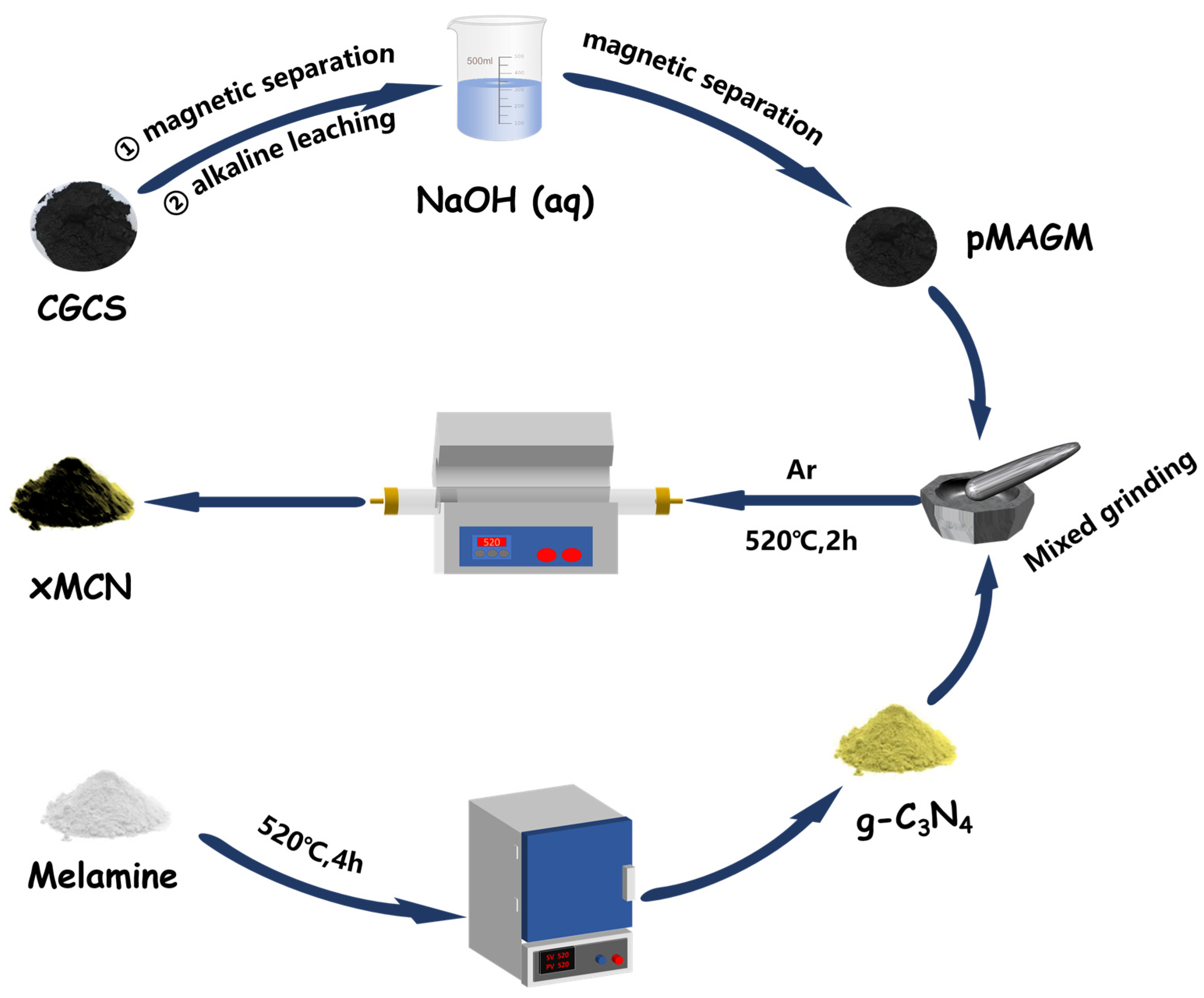
The preparation method of MCN is shown in Figure 1. Weighing 1 g of g-C3N4 (The synthesis of g-C3N4 is described in Text S1, and all subsequent abbreviations are CN) powder in a mortar and pestle, 100 mg, 500 mg, and 900 mg of p MAGM material were added according to the mass ratios of 10%, 50%, and 90%, respectively. Then, the mixture was fully ground to make a homogeneous mixture of the two. The mixed materials were placed in a tube furnace under an argon atmosphere, and the calcination procedure was set as follows: the target temperature was 520 °C, the temperature increase rate was 10 °C/min, and the holding time was 2 h. At the end of calcination, the yellow-brown powder was obtained and labeled as 10% MCN, 50% MCN, and 90% MCN, respectively.

Figure 1.
Preparation process diagram of MCN.
2.4. Experimental Degradation of Tetracycline by MCN
The experiment was carried out at room temperature under atmospheric pressure. The light source used was a xenon lamp with a 420 nm visible light filter, and the antibiotic-simulated wastewater used was tetracycline wastewater (50 mg/L) prepared with deionised water. Weighing 20 mg of catalyst in a beaker, adding 50 mL of tetracycline wastewater, dark reaction for a certain period of time to reach the adsorption equilibrium state, sampling every 20 min, using a 0.22 μm filter head to filter out the excess catalyst, collecting 4 mL of filtrate in a centrifuge tube, UV spectrophotometer, 355 nm to determine the absorbance of tetracycline, for calculation of the removal rate in the dark reaction state. After the dark reaction reached the adsorption equilibrium (the dark reaction time in this experiment was 2 h, determined by the above dark reaction time), the sample was irradiated under visible light for 1 h. Samples were taken every 10 min, and the excess catalyst was filtered out using a 0.22 μm filter head, 4 mL of filtrate was collected in a centrifuge tube, and the absorbance of tetracycline was determined under a UV spectrophotometer for calculating the removal rate under the visible light irradiation. The free radical capture test method is described in Text S2.
3. Results and Discussion
3.1. Structure and Morphology Analysis
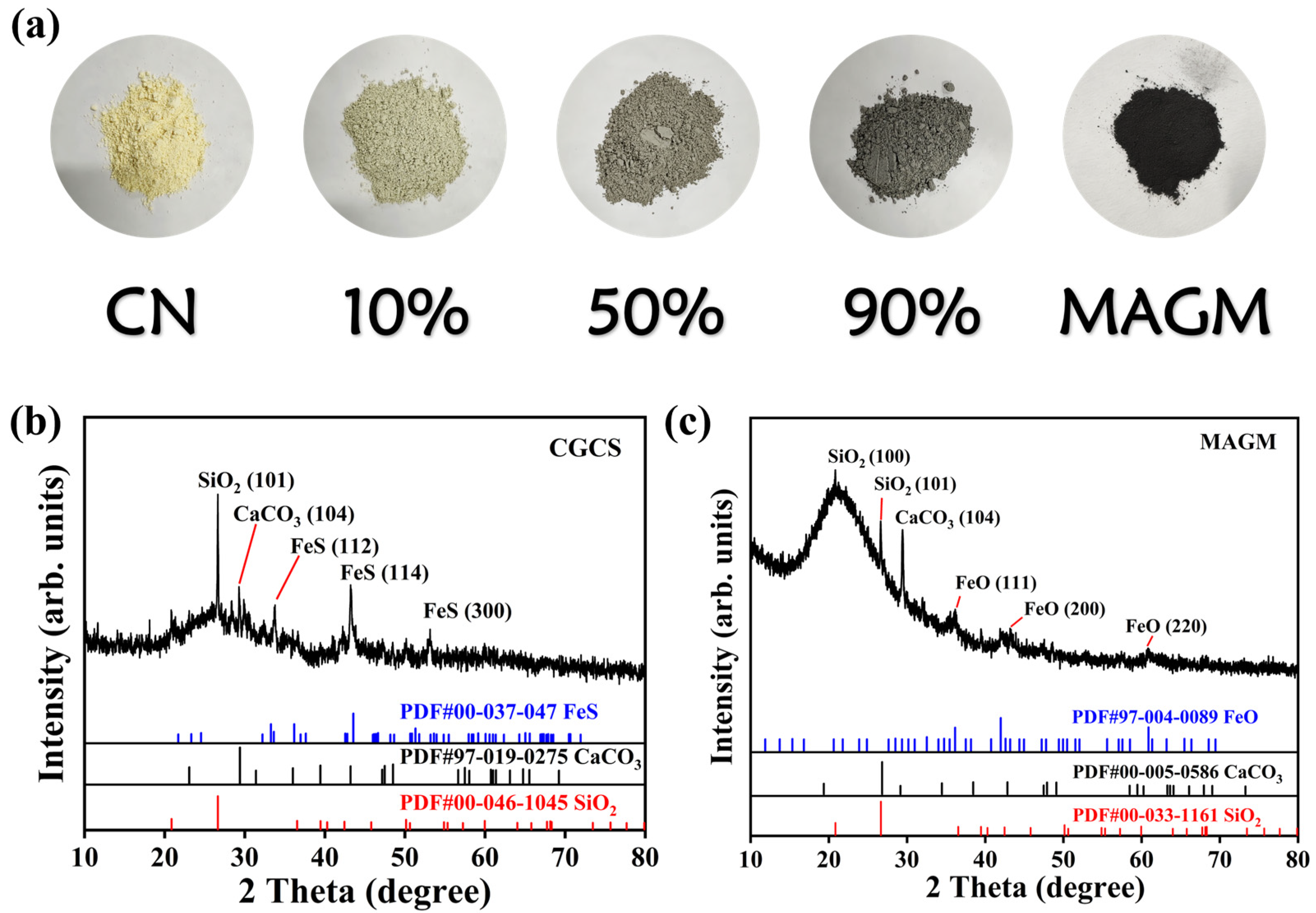
From Figure 2a, CN appears as a typical light yellow, while MAGM exhibits a deep black colour. With the increasing amount of MAGM, the composite material gradually darkens in colour. MAGM is formed from gasification coarse slag after magnetic separation, alkaline leaching, and calcination. As shown in Figure 2b, the primary crystalline components of the gasification coarse slag are SiO2, CaCO3, and FeS. However, the crystalline components of MAGM include SiO2, CaCO3, and FeO. FeO is likely derived from the alkaline leaching and calcination process [21]. Specifically, FeS reacts with NaOH as follows: FeS + 2NaOH → Na2S + Fe(OH)2. Under high-temperature conditions with an Ar atmosphere, Fe(OH)2 decomposes to form FeO. The diffraction peaks at 36.2°, 43.4°, and 60.9° in MAGM correspond to the (111), (200), and (220) crystal planes of FeO, respectively, which accounts for the magnetic properties of MAGM (Figure 2c).
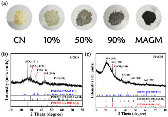
Figure 2.
(a) Appearance of the five samples; X-ray diffraction spectra of (b) Coal gasification residue and (c) MAGM.
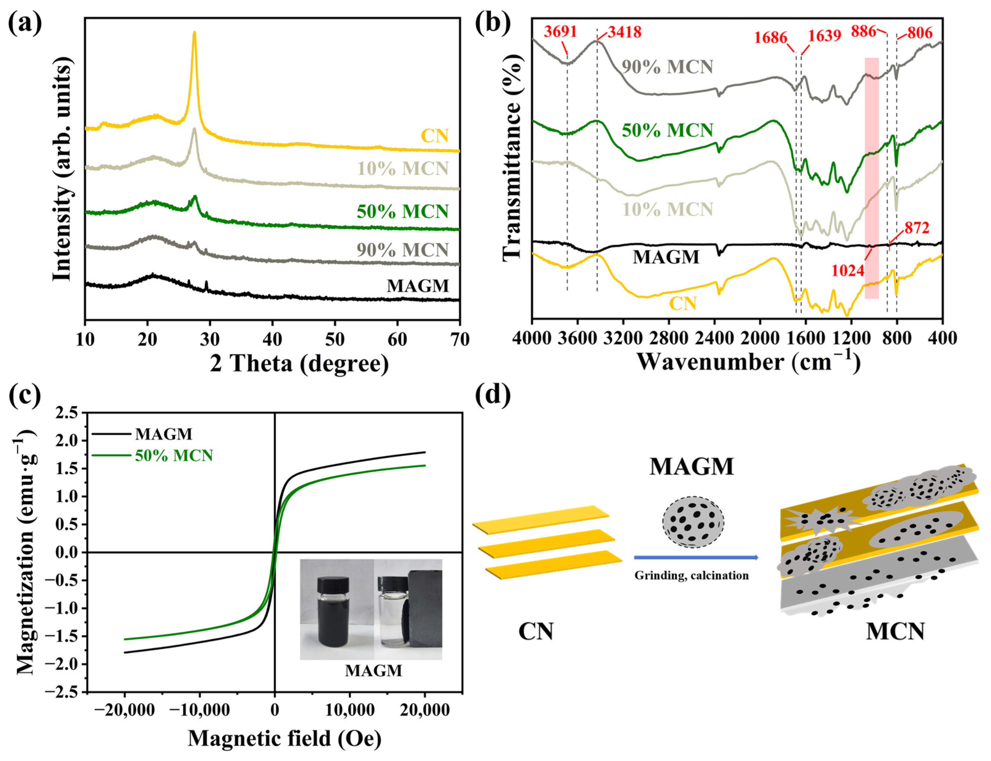
The XRD plots of the composites are shown in Figure 3a, and the CN material exhibits two diffraction peaks at 13.0° and 27.5°, corresponding to the (100) and (002) crystal planes of graphitic carbon nitride, respectively. They could be attributed to the planar filling and interlayer stacking structure of graphitic carbon nitride [22,23]. After the composite formation of MAGM and CN, as the proportion of MAGM increases, the intensities of CN’s (100) and (002) crystal planes gradually diminish, whereas the intensities of MAGM’s (101) and (104) crystal planes progressively enhance. This is due to the introduced MAGM shielding the X-ray radiation from CN’s surface, thereby reducing the intensity of CN’s diffraction peaks.
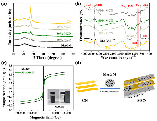
Figure 3.
(a) X-ray diffraction spectra of magnetic composite photocatalytic materials; (b) FT-IR spectroscopy of magnetic composite photocatalytic materials; (c) Hysteresis loops for MAGM and 50% MCN; (d) Schematic diagram of CN and MAGM composite process.
Fourier Transform Infrared Spectroscopy (FT-IR) was employed to detect the functional groups on the material surface (Figure 3b). The peak near 810 cm−1 is associated with the triazine units of CN; the vibration peaks between 1200~1600 cm−1 correspond to the stretching vibration of the C-N heterocyclic bond; the vibration peaks between 3600~3650 cm−1 corresponds to the stretching vibration of -NH2 [24,25]. In MAGM, the peak around 3400 cm−1 is attributed to the hydroxyl group, which represents adsorbed-free water on the surface. The Si-O peak appears at 1024 cm−1, and the absorption peak at 625 cm−1 is attributed to the Si-Si bonding. These absorption peaks can be identified in the CN materials at different blending ratios, confirming the successful preparation of the composite material.
The presence of FeO may give the composite material a certain of magnetic properties. To further verify the presence of magnetism in the material, the hysteresis loops of MAGM and 50% MCN magnetic photocatalytic composites are shown in Figure 3c. The saturation magnetisation of MAGM and 50% MCN is 1.79 emu·g−1 and 1.55 emu·g−1, respectively. The decrease in saturation magnetisation intensity of 50% MCN is due to the doping of CN in a process similar to Figure 3d. Nevertheless, the composite still maintains significant saturation magnetisation, enabling efficient separation in an external magnetic field and thereby facilitating its reuse.
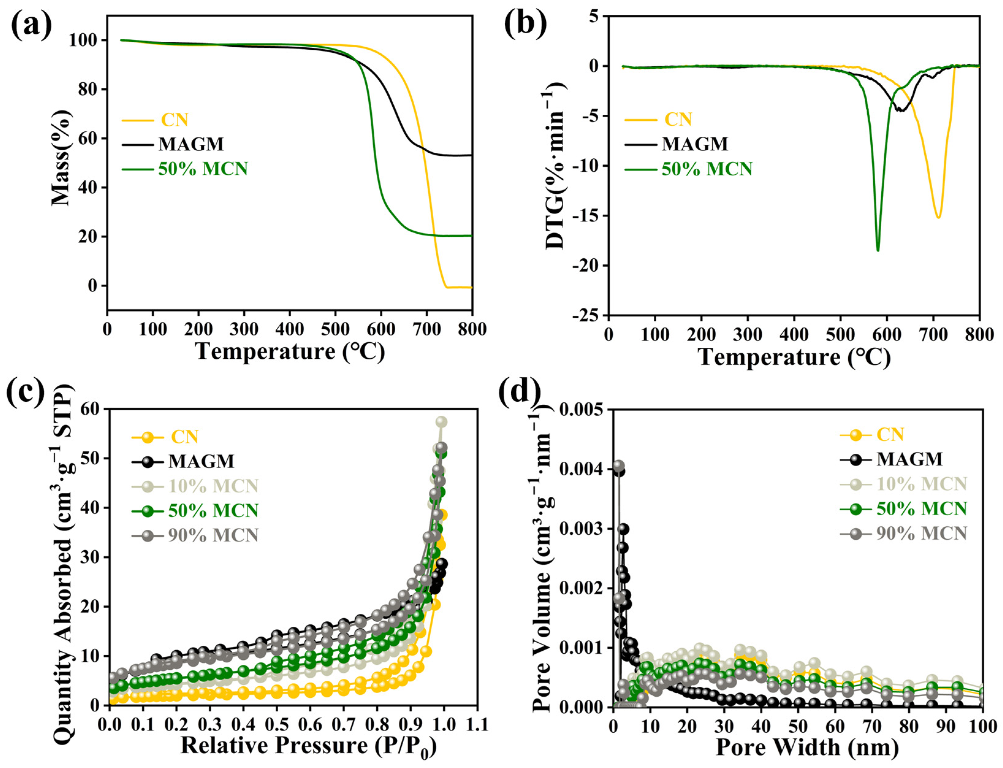
The thermal stability of the magnetic composite photocatalytic material was investigated using thermogravimetric analysis (Figure 4a). The mass loss of CN between 30 °C and 260 °C was 1.86%, which is attributed to the removal of adsorbed-free water from CN at high temperatures. Between 647 °C and 730 °C, the mass loss was 98.89%, which is attributed to the destruction of the terminal amino groups and triazine ring structure in CN. MAGM showed a mass loss of 2.69% between 30 °C and 340 °C, which is due to the removal of adsorbed-free water from the magnetic gasification slag at high temperatures. Between 576 °C and 657 °C, the mass loss was 40.44%, which is attributed to the reaction of residual carbon in MAGM with oxygen to form CO2 [26]. For the 50% MCN composite, the mass loss between 30 °C and 280 °C was 1.68%, which corresponds to the removal of adsorbed free water. Between 565.8 °C and 698 °C, a mass loss of 77.94% was observed, which is attributed to the combustion of residual carbon in the gasification slag and the self-decomposition of graphitic carbon nitride. The composite material finally left 20.38% of its mass, which consists of high-melting point substances such as silicates and aluminates from MAGM. Since the composite material is used for the removal of organic pollutants from aqueous solutions at ambient temperature, this thermal loss does not affect its application.
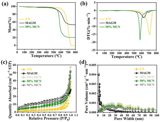
Figure 4.
CN, MAGM and 50% MCN thermogravimetric (a) and DTG (b); N2 adsorption-desorption curve (c) and pore distribution (d) of magnetic composite photocatalytic materials.
The specific surface area and pore distribution of the magnetic composite photocatalytic material were determined using nitrogen adsorption-desorption measurements. The nitrogen adsorption-desorption isotherms of the five catalysts exhibited type IV characteristics, which are indicative of mesoporous adsorption behaviour (Figure 4c) [27]. The adsorption-desorption curve of CN resembled a type H4 hysteresis loop, suggesting that CN has a mixture of micropores and mesopores. The adsorption-desorption curve of MAGM resembled a type H3 hysteresis loop, indicating the presence of slit-like pores. As MAGM was combined with CN in varying proportions, the hysteresis loop gradually shifted towards the H3 type, suggesting that the pore structure of the composite material became more slit-like. Both H3 and H4 hysteresis loops suggest that the pore structures of the five catalysts are irregular.
The specific surface area of CN was found to be 6.6991 m2·g−1, while that of MAGM was 31.2093 m2·g−1. When MAGM was combined with CN at different ratios, the specific surface areas of the composites were 15.5287 m2·g−1, 19.7228 m2·g−1, and 29.9997 m2·g−1, respectively (Table S2). The overall specific surface area of the composites increased progressively. The increase in the specific surface area of the composite material provides more active sites for the adsorption of pollutants. The pore size distribution of CN primarily falls within the range of 20–40 nanometers, characterized by a low pore volume. This suggests that while CN possesses relatively large pores, they are present in limited quantities. The pore distribution of MAGM is mainly between 5–15 nanometers with a large pore volume, indicating that MAGM has small pores but a higher pore count (Figure 4d). When MAGM was combined with CN, the pore structure of the composite material gradually changed with increasing MAGM content, showing a trend of increasing pore count and decreasing pore size.
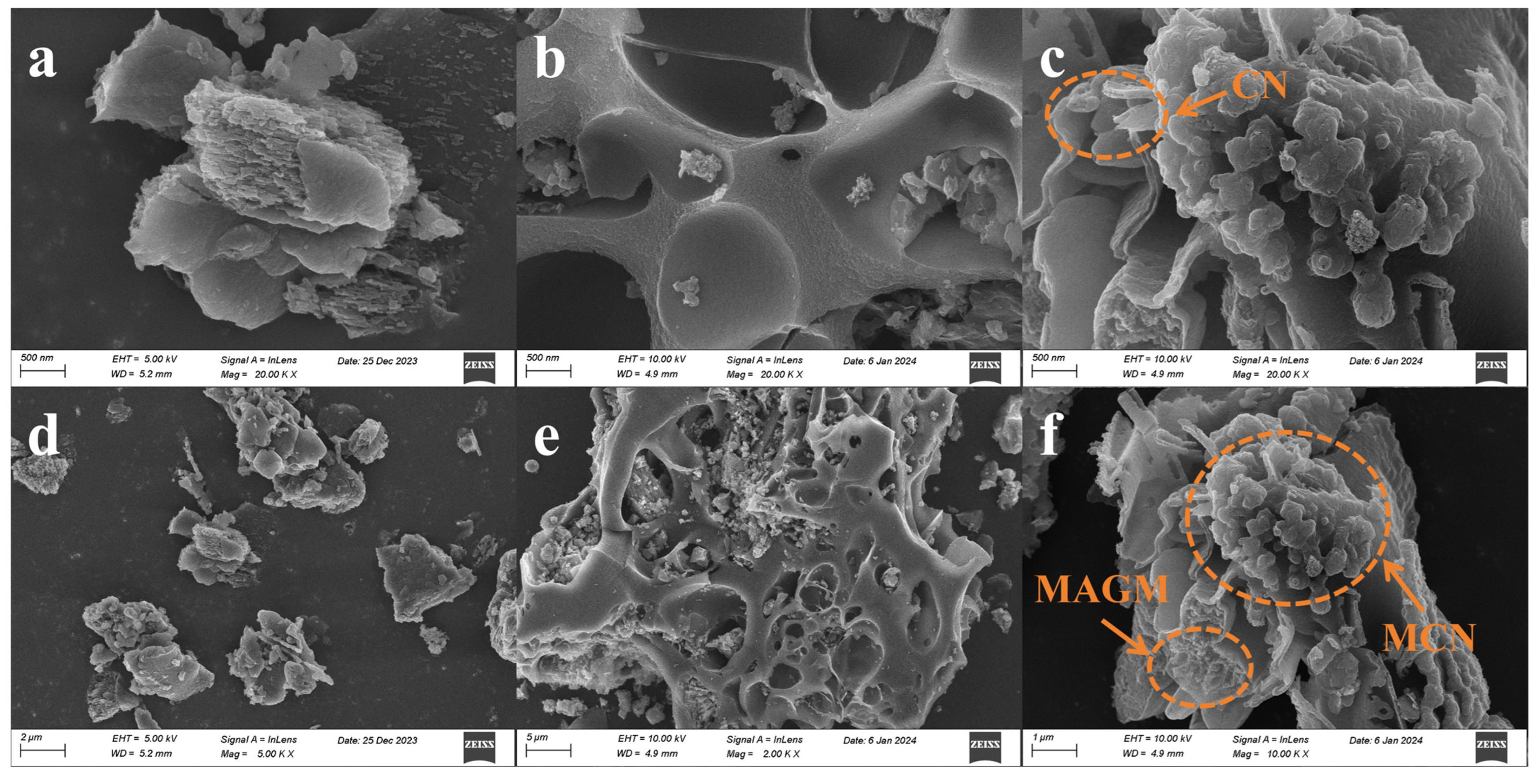
The micro-surface morphology of the catalysts was investigated using Scanning Electron Microscopy (SEM). CN exhibits a multilayer blocky stacked structure, with pores primarily concentrated in the interlayer stacking, displaying irregularity (Figure 5a,d). MAGM mainly consists of a porous structure with an irregular pore size distribution, which is consistent with the pore distribution and specific surface area analysis of MAGM (Figure 5b,e). As shown in Figure 5c,f, when MAGM is combined with CN, the composite material exhibits a layered stacking and porous fragment assembly, with MAGM coating the surface of CN. The introduction of MAGM provides CN with abundant pores, which is consistent with the specific surface area and pore analysis of the composite material [28].

Figure 5.
Scanning electron micrographs of magnetic composite photocatalytic materials: (a,d) CN; (b,e) MAGM; (c,f) 50% MCN.
3.2. Degradation Performance of Tetracycline by MCN
As shown in Figure 6a, after the magnetic composite photocatalyst reaches adsorption-desorption equilibrium with the tetracycline (TC) solution in the liquid phase, all of the catalyst’s active sites are occupied by TC. CN, due to its smaller specific surface area and pore volume, has a limited capacity to adsorb TC, reaching only 5%. MAGM, derived from gasification coarse slag via an alkaline leaching reaction, is a porous material with a larger specific surface area, resulting in an adsorption capacity for TC of 24%. With the composite of 10%, 50%, and 90% MAGM and CN, the specific surface area and pore volume of the composites increase, and the degradation capacities for TC increase to 9%, 15%, and 19%, respectively. The performance of the composite materials in degrading TC upon illumination is shown in Figure 6b. After the photocatalyst is excited by light, CN achieves approximately 30% degradation of TC, while MAGM achieves only 10% degradation. This is likely due to the iron and titanium oxides in MAGM, which, upon light excitation, generate electrons, and also due to the photodegradation of TC itself. When MAGM and CN are combined in varying proportions, the degradation rate of TC increases, reaching 55%, 82%, and 71%, respectively. This improvement can be attributed to the introduction of MAGM, which provides more active sites for the degradation process.
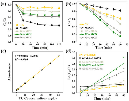
Figure 6.
(a) Dark adsorption of TC by the magnetic composite photocatalytic material; (b) Degradation of TC under light irradiation; (c) Standard curve of TC; (d) First-order kinetic fitting of the photocatalytic degradation.
Based on the standard curve of TC (Figure 6c), the photocatalytic degradation kinetics under visible light were fitted. The rate constants for CN and MAGM were found to be 0.00898 and 0.00378, respectively. As the proportion of MAGM increased, the rate constants gradually increased to 0.01316, 0.04267, and 0.02861. This indicates that the introduction of MAGM promoted the photocatalytic degradation of TC (Figure 6d). With the addition of MAGM, the composite samples have magnetic properties, which are favourable for recovery under a magnetic field. However, too much MAGM in MCN would cover the active sites of the catalyst, leading to a decrease in the catalytic degradation performance of tetracycline, which is consistent with the experimental results. After the photocatalytic degradation of TC, the remaining solution was collected in a sample bottle. Upon applying a magnetic field, the catalyst was attracted to the right side of the bottle, and the surface catalyst was effectively separated via magnetic recovery.
3.3. Photoelectric Properties of MCN
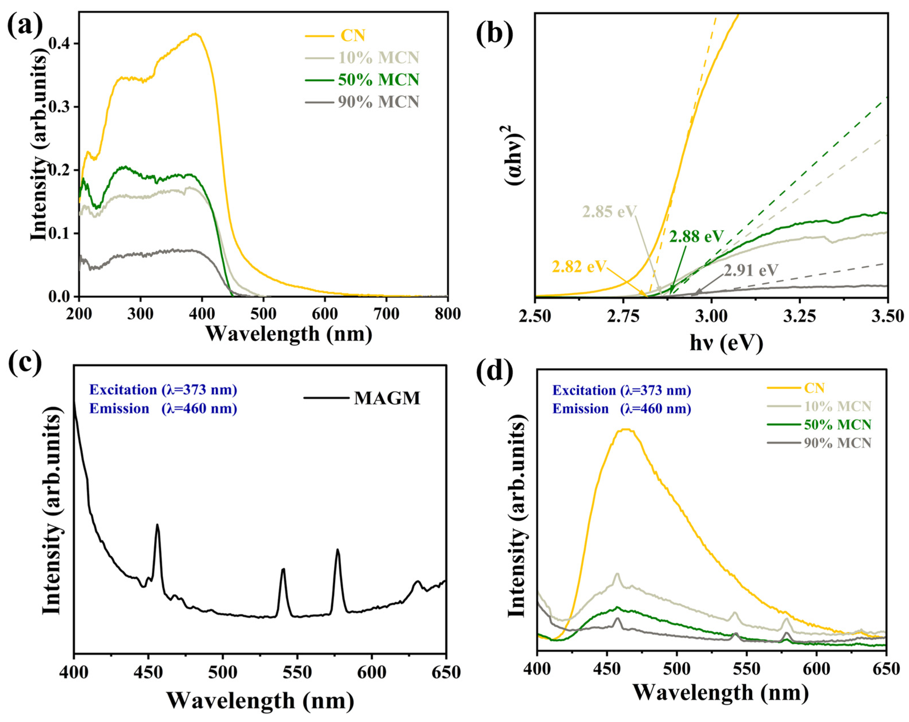
To further investigate the effect of MAGM doping on the photoresponse of CN, the UV-visible absorption spectra of the magnetic composites are shown in Figure 7a. The blue shift of the absorption edge of the composites compared to pure CN indicates that the forbidden bandwidth of the product becomes larger after compositing MAGM with CN, which is caused by the morphology of carbon nitride from bulk to nanosheets [29]. The larger forbidden bandwidth facilitates the photogenerated carrier redox capacity, which is conducive to the photocatalytic degradation of organic pollutants. Figure 7c,d shows the fluorescence spectra (PL) of the samples, and the strength of the characteristic peaks reflects the high efficiency of photogenerated electron-hole complexation [30]. It can be seen that the fluorescence intensities of the composite samples were all reduced compared with that of pure CN, and the fluorescence intensities of the composite samples were 10% MCN > 50% MCN > 90% MCN in the order of each composite sample, which indicated that the addition of MAGM could obviously improve the separation efficiency of the photogenerated electron-hole pairs, which was conducive to the enhancement of the photocatalytic activity of CN [31].
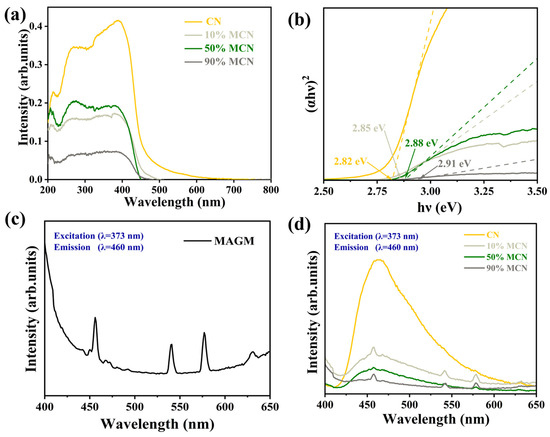
Figure 7.
(a) UV-Vis Diffuse Reflectance Spectroscopy (DRS); (b) Bandgaps of different samples; (c) Photoluminescence (PL) spectrogram of MAGM; (d) Photoluminescence spectrograms of CN and x MAGM.
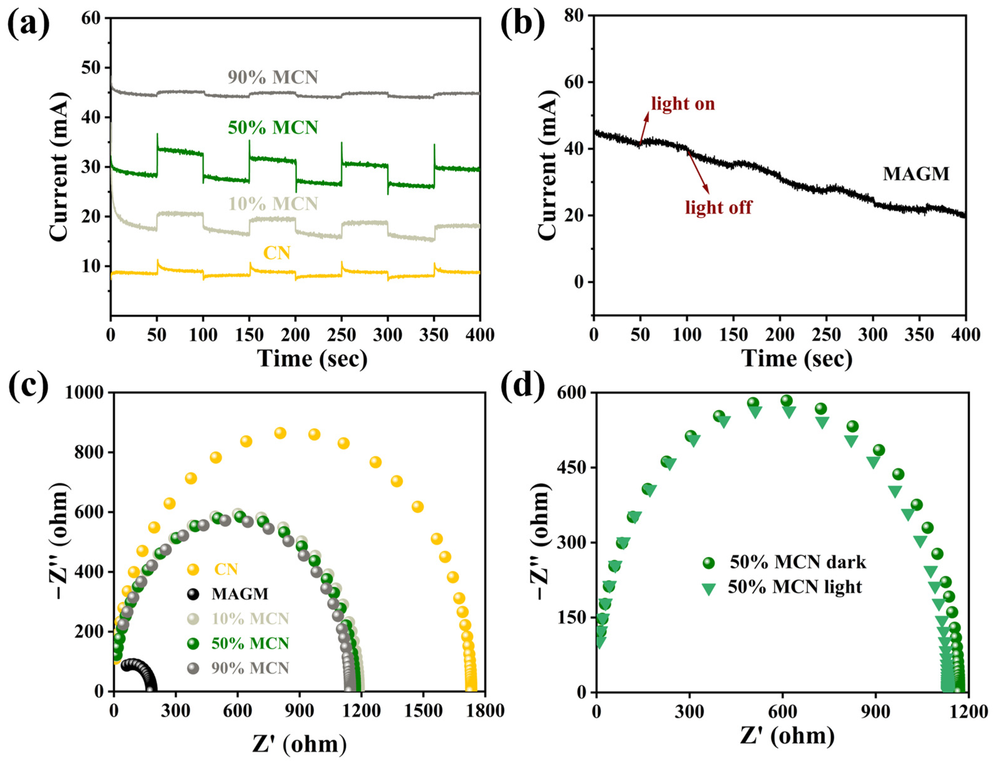
To further investigate the reasons for the improvement in the photocatalytic performance of CN by MAGM, electrochemical methods were used to study the transient photocurrent responses and impedance of CN, MAGM, 10% MCN, 50% MCN, and 90% MCN under visible light irradiation. As shown in Figure 8a, compared to the transient photocurrent intensity of CN, the transient photocurrent of the composites with different proportions of MAGM (10% MCN, 50% MCN, and 90% MCN) initially increased and then decreased. The 50% MCN composite exhibited the highest photocurrent intensity, indicating that MAGM effectively enhances the carrier migration dynamics of the material, generating more photoelectrons [32].

Figure 8.
(a) Transient photocurrent responses of CN, 10% MCN, 50% MCN, and 90% MCN; (b) Transient photocurrent response of MAGM; (c) Impedance fitting spectra of CN, MAGM, 10% MCN, 50% MCN, and 90% MCN; (d) Impedance fitting spectra of 50% MCN under light and dark conditions.
MAGM also produced a transient photocurrent signal, which can be attributed to the presence of transition metal oxides such as titanium and iron in the gasification slag. These metal oxides likely generate a weak photocurrent under light irradiation (Figure 8b). Furthermore, compared to CN, the impedance radius of the composites (10% MCN, 50% MCN, and 90% MCN) is much smaller, suggesting that the introduction of MAGM effectively improves the material’s ability to transport electrons (Figure 8c). The impedance radius of 50% MCN under light irradiation is smaller than that under dark conditions, which further proves that MAGM enhances the electron transfer ability (Figure 8d) [33]. Therefore, MAGM can improve the carrier migration dynamics of CN, generating more photoelectrons and also enhancing CN’s ability to transport electrons. This plays a significant role in improving the photocatalytic performance.
3.4. Mechanism of TC Degradation by MCN
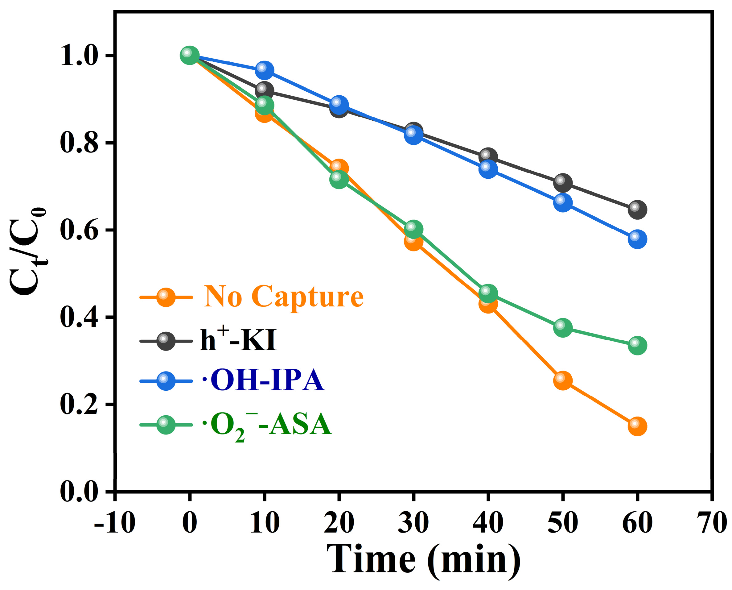
To clarify the mechanism of photocatalytic degradation of TC, we designed reactive oxygen species (ROS) trapping experiments. Under visible light irradiation, the composite photocatalyst achieved a degradation rate of 82% for TC. Upon the addition of a hole scavenger (KI), the degradation rate of TC was significantly inhibited, reducing to only 35%. When isopropanol (IPA) was used to capture hydroxyl radicals, the degradation rate of TC decreased to 43%. Similarly, the addition of ascorbic acid (ASA) as a scavenger for superoxide radicals resulted in a degradation rate of 57%. These experimental results suggest that holes, hydroxyl radicals, and superoxide radicals all play an active role in the degradation of TC (Figure 9). Therefore, the possible mechanisms for degrading TC are as follows (Equations (1)–(4)), and combined with HPLC-MS to analyse the m/z of various by-products produced during the degradation process (Table S4), it was concluded that the possible pathways for TC degradation by MCN are shown in Figure S2.
50% MCN + hν → h+ + e−
h+ + H2O → OH
e− + O2 → O2−
h+/·OH/·O2− + TC → intermediates + CO2 + H2O

Figure 9.
Free Radical Trapping Experiment for TC Degradation by 50% MCN.
3.5. Cycling Performance of MCN in TC Degradation
The ability of photocatalysts to be recycled is a prerequisite for practical applications. As shown in Figure 10a,b, the 50% MCN composite was tested for TC degradation over five cycles. After five dark adsorption cycles, the removal efficiency of TC through adsorption was 12%, with a decrease of 20% in adsorption efficiency. Under visible light irradiation, the degradation rate of TC after five cycles reached 70%, with a 14% reduction in photocatalytic degradation efficiency. The XRD patterns before and after cycling revealed that the SiO₂ diffraction peak at 26.5° was enhanced after the cyclic degradation process. MAGM is a magnetic carbon-silicon composite with a porous structure, mainly carbon and silicoaluminate minerals coated with each other, and some CN and MCN are also covered on the surface after the composite with CN. Therefore, residual carbon and surface coverings may have been washed off from the surface of the catalyst during the reaction cycle, thus exposing the MAGM-enhanced SiO₂ peak (Figure 10c). No significant changes were observed in the infrared (FT-IR) spectra before and after the cycles, indicating the structural stability of the composite (Figure 10d). After five cycles, the wastewater could still be effectively treated, and the catalyst powder could be recovered using a magnet (Figure 10e). Therefore, the 50% MCN composite exhibits stable recycling performance and holds great potential for practical applications.
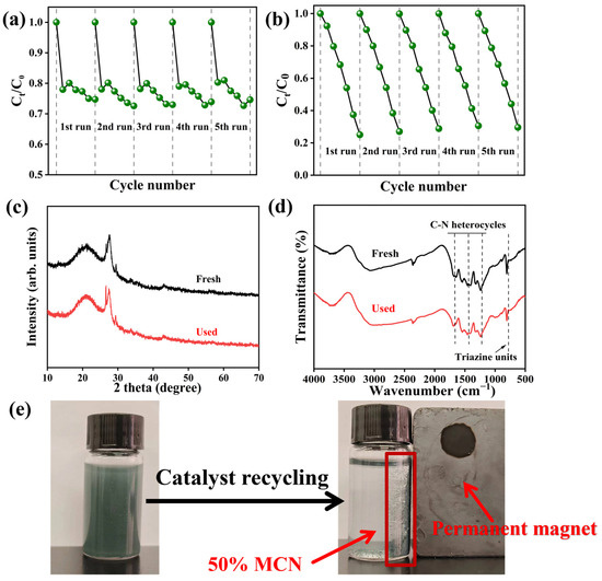
Figure 10.
50% MCN cycle five times degradation of TC: (a) dark reaction; (b) illumination; (c) XRD before and after cycling; (d) pre- and post-cycle infrared spectroscopy; (e) Magnetic recovery process after 5 cycles of TC degradation (Recovery time < 30 s).
4. Conclusions
In this study, we changed the previous way of modifying graphitic phase carbon nitride at the cost of consuming existing resources by modifying graphitic phase carbon nitride with coal-based solid waste coal gasification slag. The process innovatively modified magnetic particles sorted from the gasification slag as carriers to be composite with graphite phase carbon nitride and successfully prepared a magnetically recoverable composite photocatalyst. The best catalytic performance was obtained with 50% MCN, achieving compatibility between controlled magnetic recovery and adsorption catalytic performance. The final results are close to expectations and provide a new way for the high-value-added resourcing of solid waste.
- (1)
- Under visible light irradiation, the 50% MCN composite photocatalyst has a good degradation rate of simulated tetracycline solution, the dark reaction adsorption degradation rate can reach 15%, and the light reaction degradation rate can reach 82%, and it has a magnetic recovery effect. The reason is that after the composite of MAGM and CN, the specific surface area is effectively increased by three times, and the active sites of photocatalytic reaction are increased. The impedance of MAGM is low, the ability to transport electrons is enhanced, and the transient photocurrent intensity of the composite is higher than that of ordinary carbon nitride, which has a low rate of photogenerated electron and hole complexation.
- (2)
- After cyclic degradation of tetracycline five times, the activity of 50% MCN only decreased by 14%, and the structure did not change. The magnetic separation of 50% MCN in solution was still achieved within 30 s, and the overall catalyst recovery was above 95%. In this study, the performance and cost of the catalysts were optimised by cleverly exploiting the characteristics of solid wastes, and the idea of “unconventional material design” provides a new paradigm for the development of environmentally functional materials.
Supplementary Materials
The following supporting information can be downloaded at: https://www.mdpi.com/article/10.3390/pr13030770/s1, Text S1: Preparation of carbon nitride in graphite phase; Text S2: Free radical trapping experiments for the degradation of tetracycline by magnetic photocatalytic composites; Table S1: Other chemical components in coal gasification slag; Table S2 Textural properties of the samples; Table S3 Comparison of various CN-based photocatalysts for the degradation of TC; Table S4 Molecular structures, molecular formulas, and m/z values of TC and intermediates; Figure S1 Magnetic separation MAGM effect diagram; Figure S2 The proposed pathway of TC degradation in the MCN photocatalytic reaction system. References [34,35,36,37,38,39] are cited in the supplementary materials.
Author Contributions
Y.Y.: Writing-review and editing, Investigation, Data curation. T.Y.: Investigation, Data analysis and partial writing. G.D.: Writing review and editing, Supervision, Resources, financial support. C.W.: Writing-review and editing, Supervision. The authors declare no conflicts of interest. All authors have read and agreed to the published version of the manuscript.
Funding
Financial support by the National Natural Science Foundation of China (Grant No. 21876104) is gratefully acknowledged. Supported by the National Foreign Experts project high-end foreign experts introduction plan (G2022041003).
Data Availability Statement
The original contributions presented in this study are included in the article/Supplementary Materials. Further inquiries can be directed to the corresponding authors.
Conflicts of Interest
The authors declare no conflicts of interest.
References
- Bielen, A.; Šimatović, A.; Kosić-Vukšić, J.; Senta, I.; Ahel, M.; Babić, S.; Jurina, T.; Plaza, J.J.G.; Milaković, M.; Udiković-Kolić, N. Negative environmental impacts of antibiotic-contaminated effluents from pharmaceutical industries. Water Res. 2017, 126, 79–87. [Google Scholar] [CrossRef] [PubMed]
- Wang, J.T.; Cai, Y.L.; Liu, X.J.; Zhang, X.D.; Cai, F.Y.; Cao, H.L.; Zhong, Z.; Li, Y.F.; Lü, J. Unveiling the visible-light-driven photodegradation pathway and products toxicity of tetracycline in the system of Pt/BiVO4 nanosheets. J. Hazard. Mater. 2022, 424, 127596. [Google Scholar] [CrossRef]
- Zainab, S.M.; Junaid, M.; Xu, N.; Malik, R.N. Antibiotics and antibiotic resistant genes (ARGs) in groundwater: A global review on dissemination, sources, interactions, environmental and human health risks. Water Res. 2020, 187, 116455. [Google Scholar] [CrossRef] [PubMed]
- Qin, K.; Wei, L.L.; Li, J.J.; Lai, B.; Zhu, F.Y.; Yu, H.; Zhao, Q.L.; Wang, K. A review of ARGs in WWTPs: Sources, stressors and elimination. Chin. Chem. Lett. 2020, 31, 2603–2613. [Google Scholar] [CrossRef]
- Han, Y.; Yang, L.; Chen, Y.; Cai, Y.; Shen, G. Removal of veterinary antibiotics from swine wastewater using anaerobic and aerobic biodegradation. Sci. Total Environ. 2019, 709, 136094. [Google Scholar] [CrossRef]
- Mangla, D.; Sharma, A.; Ikram, S. Critical review on adsorptive removal of antibiotics: Present situation, challenges and future perspective. J. Hazard. Mater. 2022, 425, 127946. [Google Scholar] [CrossRef] [PubMed]
- Ai, Y.J.; Liu, Y.; Huo, Y.Z.; Zhao, C.F.; Sun, L.; Han, B.; Cao, X.R.; Wang, X.K. Insights into the adsorption mechanism and dynamic behavior of tetracycline antibiotics on reduced graphene oxide (RGO) and graphene oxide (GO) materials. Environ. Sci. Nano 2019, 6, 3336–3348. [Google Scholar] [CrossRef]
- Wang, Y.; He, Y.; Li, X.; Nagarajan, D.; Chang, J.S. Enhanced biodegradation of chlortetracycline via a microalgae-bacteria consortium. Bioresour. Technol. 2022, 343, 126149. [Google Scholar] [CrossRef]
- Shao, S.; Wu, X. Microbial degradation of tetracycline in the aquatic environment: A review. Crit. Rev. Biotechnol. 2020, 40, 1010–1018. [Google Scholar] [CrossRef]
- Liu, R.; Zhang, C.J.; Liu, R.J.; Sun, Y.; Ren, B.Q.; Tong, Y.H.; Tao, Y. Advancing antibiotic detection and degradation: Recent innovations in graphitic carbon nitride (g-C3N4) applications. J. Environ. Sci. 2025, 150, 657–675. [Google Scholar] [CrossRef]
- Yuan, A.; Lei, H.; Xi, F.N.; Liu, J.Y.; Qin, L.; Chen, Z.; Dong, X.P. Graphene quantum dots decorated graphitic carbon nitride nanorods for photocatalytic removal of antibiotics. J. Colloid Interface Sci. 2019, 548, 56–65. [Google Scholar] [CrossRef] [PubMed]
- Zhao, Z.W.; Sun, Y.J.; Dong, F. Graphitic carbon nitride based nanocomposites: A review. Nanoscale 2015, 7, 15–37. [Google Scholar] [CrossRef]
- Verma, A.; Sharma, G.; Wang, T.; Kumar, A.; Dhiman, P.; García-Peñas, A. Graphitic carbon nitride (g-C3N4)-based magnetic photocatalysts for removal of antibiotics. Carbon Lett. 2024, 35, 45–73. [Google Scholar] [CrossRef]
- Mousavi, M.; Habibi-Yangjeh, A.; Pouran, S.R. Review on magnetically separable graphitic carbon nitride-based nanocomposites as promising visible-light-driven photocatalysts. J. Mater. Sci. Mater. Electron. 2018, 29, 1719–1747. [Google Scholar] [CrossRef]
- Su, S.F.; Tahir, M.H.; Cheng, X.X.; Zhang, J.S. Modification and resource utilization of coal gasification slag-based material: A review. J. Environ. Chem. Eng. 2024, 12, 112112. [Google Scholar] [CrossRef]
- Zhu, Y.; Wu, Y.; Zhang, Y. Preparation of hierarchically porous carbon ash composite material from fine slag of coal gasification and ash slag of biomass combustion for CO2 capture. Sep. Purif. Technol. 2024, 330, 125452. [Google Scholar] [CrossRef]
- Liu, D.; Wang, W.; Tu, Y.; Ren, G.; Yan, S.; Liu, H.; He, H.; Jin, M. Flotation specificity of coal gasification fine slag based on release analysis. J. Clean. Prod. 2022, 363, 132426. [Google Scholar] [CrossRef]
- Zhao, Y.; Chan, W.P.; Chin, V.; Boon, Y.Z.; Fu, X.; Gu, Y.; Oh, J.; Lisak, G. Technical and environmental assessment of sludge-derived slag generated from high temperature slagging co-gasification process as a sustainable construction material. Waste Manag. 2024, 190, 186–196. [Google Scholar] [CrossRef]
- Du, M.; Huang, J.; Liu, Z.; Xing, Z.; Fang, Y. Reaction characteristics and evolution of constituents and structure of a gasification slag during acid treatment. Fuel 2018, 224, 178–185. [Google Scholar] [CrossRef]
- Lyu, F.Y.; Chu, M.; Sun, X.B.; Hu, J.B.; Shi, X.; Yuan, Y.F. Magnetization roasting characteristic and mechanism of gasification slag from coal-water slurry gasifier. Energy Sources Part A Recovery Util. Environ. Eff. 2024, 46, 2894–2906. [Google Scholar] [CrossRef]
- Sun, X.H.; Sun, R.; Liu, D.R.; Liu, Z.; Wang, D.M.; Cao, W.L.; Zhao, Y.X. Preparation of coal gasification coarse slag-based alkaline activator and its activation mechanism in alkali-activated slag. Cem. Concr. Compos. 2024, 152, 105648. [Google Scholar] [CrossRef]
- Fina, F.; Callear, S.K.; Carins, G.M.; Irvine, T.S. Structural investigation of graphitic carbon nitride via XRD and neutron diffraction. Chem. Mater. 2015, 27, 2612–2618. [Google Scholar] [CrossRef]
- Song, Z.; Hou, J.; Raguin, E.; Pedersen, A.; Eren, E.O.; Senokos, E.; Tarakina, N.V.; Giusto, P.; Antonietti, M. Triazine-Based Graphitic Carbon Nitride Thin Film as a Homogeneous Interphase for Lithium Storage. ACS Nano 2024, 18, 2066–2076. [Google Scholar] [CrossRef] [PubMed]
- Liang, H.G.; Wang, A.H.; Cheng, R.L.; Chen, F.; Kannan, P.; Molochas, C.; Tsiakaras, P. Bi, K co-doped graphitic phase carbon nitride for efficient photocatalytic H2O2 production. Chem. Eng. J. 2024, 489, 151145. [Google Scholar] [CrossRef]
- Zhang, S.; Hu, C.; Ji, H.H.; Zhang, L.L.; Li, F. Facile synthesis of nitrogen-deficient mesoporous graphitic carbon nitride for highly efficient photocatalytic performance. Appl. Surf. Sci. 2019, 478, 304–312. [Google Scholar] [CrossRef]
- Li, Y.; Hou, L.H.; Wang, Y.F.; Wu, Y.L.; Wang, J.M.; Han, W.J.; Zhang, X. Classification and properties of coal gasification coarse slags. Multipurp. Util. Miner. Resour. 2024, 45, 46–51. [Google Scholar]
- Xiu, F.R.; Yu, X.; Qi, Y.Y.; Li, Y.F.; Lu, Y.W.; Wang, Y.X.; He, J.H.; Zhou, K.; Song, Z.Q.; Gao, X. A novel management strategy for removal and degradation of polybrominated diphenyl ethers (PBDEs) in waste printed circuit boards. Waste Manag. 2019, 100, 191–198. [Google Scholar] [CrossRef]
- Chegeni, M.; Mehri, M.; Dehdashtian, S. Photocatalytic bauxite and red mud/graphitic carbon nitride composites for Rhodamine B removal. J. Mol. Struct. 2021, 1242, 130752. [Google Scholar] [CrossRef]
- Zhang, C.; Qin, D.Y.; Zhou, Y.; Qin, F.Z.; Wang, H.; Wang, W.J.; Yang, Y.; Zeng, G.M. Dual optimization approach to Mo single atom dispersed g-C3N4 photocatalyst: Morphology and defect evolution. Appl. Catal. B Environ. 2022, 303, 120904. [Google Scholar] [CrossRef]
- Li, X.; Jiang, H.P.; Ma, C.C.; Zhu, Z.; Song, X.H.; Wang, H.Q.; Huo, P.W.; Li, X.Y. Local surface plasma resonance effect enhanced Z-scheme ZnO/Au/g-C3N4 film photocatalyst for reduction of CO2 to CO. Appl. Catal. B Environ. 2021, 283, 119638. [Google Scholar] [CrossRef]
- He, B.; Feng, M.; Chen, X.Y.; Sun, J. Multidimensional (0D-3D) functional nanocarbon: Promising material to strengthen the photocatalytic activity of graphitic carbon nitride. Green Energy Environ. 2021, 6, 823–845. [Google Scholar] [CrossRef]
- Zhang, Y.Q.; Sun, M.R.; Peng, M.G.; Du, E.; Xu, X.; Wang, C.C. The fabrication strategies and enhanced performances of metal-organic frameworks and carbon dots composites: State of the art review. Chin. Chem. Lett. 2023, 34, 107478. [Google Scholar] [CrossRef]
- Kumar, A.; Sharma, G.; Kumari, A.; Guo, C.S.; Naushad, M.V.; Vo, D.V.N.; Iqbal, J.; Stadler, F.J. Construction of dual Z-scheme g-C3N4/Bi4Ti3O12/Bi4O5I2 heterojunction for visible and solar powered coupled photocatalytic antibiotic degradation and hydrogen production: Boosting via I-/I3- and Bi3+/Bi5+redox mediators. Appl. Catal. B Environ. 2021, 284, 119808. [Google Scholar] [CrossRef]
- Han, K.; Dong, G.; Saeed, I.; Dong, T.; Xiao, T. Morphology and photocatalytic tetracycline degradation of g-C3N4 optimized by the coal gangue. Chin. J. Struct. Chem. 2024, 43, 38–48. [Google Scholar] [CrossRef]
- Jiang, L.; Yuan, X.; Zeng, G.; Liang, J.; Chen, X.; Yu, H.; Wang, H.; Wu, Z.; Zhang, J.; Xiong, T. In-situ synthesis of direct solid-state dual Z-scheme WO3/g-C3N4/Bi2O3 photocatalyst for the degradation of refractory pollutant. Appl. Catal. B Environ. 2018, 227, 376–385. [Google Scholar] [CrossRef]
- Xu, Z.; Jin, Y.; Xue, B.; Xing, J.; Zhang, J.; Du, Y.; Xu, Y.; Liu, D.; Zhu, Y.; Li, F. Enhanced photocatalytic performance of broken hollow tubular carbon nitride modified with nitrogen defects and hydroxyl groups for pollutant degradation and hydrogen production. Int. J. Hydrogen Energy 2024, 86, 1326–1336. [Google Scholar] [CrossRef]
- Qian, W.; Fang, Y.; Liu, H.; Deng, Y.; Li, Y.; Zhang, Y.; Diao, Z.; Li, M. Photocatalytic degradation of tetracycline hydrochloride by Mn/g-C3N4/BiPO4 and Ti/g-C3N4/BiPO4 composites: Reactivity and mechanism. Catalysts 2023, 13, 1398. [Google Scholar] [CrossRef]
- Huang, X.; Guo, F.; Li, M.; Ren, H.; Shi, Y.; Chen, L. Hydrothermal synthesis of ZnSnO3 nanoparticles decorated on g-C3N4 nanosheets for accelerated photocatalytic degradation of tetracycline under the visible-light irradiation. Sep. Purif. Technol. 2020, 230, 115854. [Google Scholar] [CrossRef]
- Ren, F.; Ouyang, E. Photocatalytic Degradation of Tetracycline Hydrochloride by g-C3N4 Modified Bi2O3. Chin. J. Mater. Res. 2023, 37, 633–640. [Google Scholar]


Disclaimer/Publisher’s Note: The statements, opinions and data contained in all publications are solely those of the individual author(s) and contributor(s) and not of MDPI and/or the editor(s). MDPI and/or the editor(s) disclaim responsibility for any injury to people or property resulting from any ideas, methods, instructions or products referred to in the content. |
© 2025 by the authors. Licensee MDPI, Basel, Switzerland. This article is an open access article distributed under the terms and conditions of the Creative Commons Attribution (CC BY) license (https://creativecommons.org/licenses/by/4.0/).