Article

A Thermodynamic Model for Performance Prediction of an Ejector with an Adjustable Nozzle Exit Position

1
School of Energy and Building Environment, Guilin University of Aerospace Technology, Guilin 541004, China
2
Faculty of Engineering, Architectural and Information Technology, University of Queensland, Brisbane 4072, Australia
3
School of Chemical Engineering, Guizhou University of Engineering Science, Bijie 551700, China
4
Guangxi Zhuang Autonomous Region Special Equipment Inspection and Research Institute, Nanning 530299, China
*
Author to whom correspondence should be addressed.
Processes 2025, 13(3), 879; https://doi.org/10.3390/pr13030879
Submission received: 15 February 2025 / Revised: 9 March 2025 / Accepted: 13 March 2025 / Published: 17 March 2025
(This article belongs to the Section Manufacturing Processes and Systems)

Abstract

:
Improving the efficiency of ejectors during off-design operations can be effectively achieved through the automatic adjustment of the nozzle exit position (NXP). A thermodynamic model for predicting the performance of an ejector with an adjustable nozzle position is proposed and validated. The key factors influencing the optimal nozzle exit position under variable operating conditions are analyzed using the model. The dimensionless optimal nozzle exit position (DONXP) of the ejector is fitted as a function of these key factors, and a nozzle exit position adjustment scheme for variable operating conditions is further derived. The proposed model has maximum errors in the entrainment ratio, critical back pressure, and nozzle exit position within ±10.70%, ±7%, and ±15.85%, respectively. When the area ratio increases, with the transition point located in the mixing chamber, the increase rates of the DONXP are within 0.068~0.195 for the R245fa, R600a, R141b, and R134a ejectors. However, when the transition point is located before the entrance of the mixing chamber, the increase rates are within 0.0009~0.0034. When the area ratio is fixed, the larger the expansion ratio, the smaller the DONXP. The DONXP can be fitted according to different cases where the turning point is located either before or after the entrance of the mixing chamber, to meet the demand for automatic adjustment of the nozzle exit position.

1. Introduction

A vapor ejector is a type of fluid machinery that can boost the pressure of a low-pressure vapor by consuming a high-pressure vapor, thereby obtaining a medium-pressure mixed vapor. The main working components of a vapor ejector include a nozzle, a suction chamber, a mixing chamber, and a diffuser. It is characterized by its simple structure, absence of moving parts, minimal maintenance requirements, and low application costs [1]. It is widely used in low-grade heat energy utilization, such as solar ejector refrigeration systems [2], multi-effect distillation [3], and other fields. The nozzle exit position (NXP), being a critical design parameter that significantly influences ejector efficiency, has consistently remained a central focus in ejector performance optimization studies.
Fu et al. conducted numerical investigations using computational fluid dynamics to examine the relationship between the nozzle exit position and entrainment ratio in vapor ejector systems. Under the operational conditions of 0.6 MPa in primary flow pressure, 0.015 MPa in secondary flow pressure, and 0.04 MPa in back pressure, the experimental results demonstrated that an ejector configuration with a 3.7 mm nozzle throat and a 15.8 mm mixing chamber diameter achieved optimal performance at a nozzle exit position of approximately 62.9 mm [4]. Ramesh et al. studied the NXP of a cylindrical mixing chamber ejector through experiments. For an ejector with a nozzle throat diameter of 6.4 mm and a mixing chamber diameter of 30 mm operating under a primary pressure of 0.2 MPa, a secondary pressure of 0.00123 MPa, and a critical back pressure of 0.0043 MPa, the ideal nozzle exit position was determined to be 11.8 mm, as reported in reference [5]. Through computational analysis, Metin et al. [6] investigated the NXP’s influence on ejector efficiency, determining that for an R134a system operating at a primary pressure of 2.888 MPa, a secondary pressure of 0.415 MPa, and a critical back pressure of 0.82762 MPa, maximum performance occurred when the nozzle exit position measured 2.16 times the mixing chamber diameter. Eldakamawy et al. [7]. studied the NXP of a butene ejector with a cylindrical mixing chamber through experiments. According to the reference, the ejector demonstrated optimal performance with a nozzle throat diameter of 2 mm and a mixing chamber diameter of 9 mm. The highest entrainment ratio was attained under conditions where the primary vapor pressure reached 3.56 MPa, the secondary vapor pressure was maintained at 0.085 MPa, and the critical back pressure was set at 0.279 MPa. Through numerical simulations of vapor ejectors, Han et al. [8] investigated the system performance under specific operational parameters, including a primary flow pressure of 0.36 MPa, a secondary flow pressure of 0.00317 MPa, and a back pressure of 0.004 MPa. Their findings revealed that for an ejector configuration featuring a 2.5 mm nozzle throat diameter and a 28 mm mixing chamber diameter, maximum entrainment efficiency was achieved at an NXP of 10 mm. Geng et al. [9] conducted comprehensive experimental and computational analyses to evaluate ejector performance characteristics in Joule–Thomson cryogenic cooling systems. Under the specified operational parameters, including a primary vapor pressure of 8 MPa, a secondary vapor pressure of 0.05 MPa, and a back pressure of 0.12 MPa, the experimental investigations revealed that an ejector configuration with a nozzle throat diameter of 0.18 mm and a mixing chamber diameter of 1.6 mm demonstrated peak entrainment efficiency at an NXP of −3 mm.
Previous investigations have primarily concentrated on identifying the optimal nozzle exit positions for ejectors under fixed design parameters [10], with limited exploration of real-time NXP adaptation strategies for variable operational scenarios. As we all know, adjusting the NXP under off-design conditions can transform part of the low-efficiency working conditions of the ejector into high-efficiency working conditions [11], but it is a practical problem to be solved urgently in many ejector application fields to go deep into the specific mathematical descriptions of quantitative aspects and use an automatic control program to adjust the nozzle in real time. In order to meet the needs of NXP adjustment of the ejector under variable working conditions, Wang et al. proposed a vapor ejector that can automatically adjust the NXP through a spring tube for the seawater desalination system [12]. Experimental results demonstrated that the ejectors with adjustable nozzle exit positions exhibited superior performance under varying conditions, achieving up to 35.8% higher entrainment ratios compared to fixed-geometry designs. However, the correlation proposed by Wang was only for an ejector with a specific size and under a specific primary vapor pressure, which is not applicable to other ejectors. Moreover, the numerical simulation results of Chen et al. [13] indicated that the optimal nozzle exit position for the variable conditions of an ejector was related not to the operating vapor pressure, but to the secondary vapor pressure. Rand et al. [14] investigated this through numerical simulation and made the first attempt to explain the effect of the nozzle exit position on the performance of the ejector using the compound choking theory. They pointed out that a correction coefficient should be applied to the thermodynamic model of the ejector, but the specific method was not provided. It can be seen that the current studies mainly use experimental or numerical simulation methods to investigate the nozzle exit positions of ejectors under variable working conditions. However, the conclusions are limited by the specific working fluids and conditions, lacking a universal basis for adjusting the nozzle exit position in practical applications of ejectors.
In this study, a thermodynamic model for performance prediction of an ejector with an adjustable nozzle exit position is proposed and validated. Based on the model, the main factors affecting the optimal ejector nozzle exit position under variable operating conditions are analyzed. Correlation equations for the optimal dimensionless nozzle exit position under variable operating conditions are then fitted using the R245fa, R134a, R600a, and R141b working fluids, and a strategy for adjusting the ejector nozzle exit position is proposed. The work performed is of great significance for improving the performance of vapor ejectors under variable working conditions.

2. Mathematical Model of Vapor Ejector

2.1. The Model of the Vapor Ejector Under the Single-Choking Mode

In the well-designed ejector structure illustrated in Figure 1, the primary vapor reaches a supersonic speed within the Laval-cavity nozzle through the conversion of pressure energy into kinetic energy. The secondary vapor also undergoes the process of pressure reduction and speed increase in the suction chamber, although its velocity remains subsonic. Between the nozzle exit (Cross-section 1) and the entrance (Cross-section 2) of the mixing chamber, the two streams interact through an annular mixing layer, which is characterized by a combined thickness. After entering the cylindrical mixing chamber, the fluid is mixed and accelerated, then flows out at a subsonic speed and into the diffuser. Finally, it is discharged after undergoing speed reduction and pressurization in the diffuser [15].
When establishing the mathematical model of the gas ejector, the assumptions made include the following: (1) Since the velocity of the ejector within the pipeline is considerably smaller in comparison to its enthalpy, the kinetic energy of the gas entering or exiting the ejector can be deemed negligible [16]. (2) Supersonic flow conditions are achieved in the primary fluid as it passes through the nozzle throat, with full expansion completion occurring at the nozzle exit section. (3) Prior to interaction with the primary jet vapor, the secondary flow maintains its initial velocity profile, exhibiting identical flow characteristics to those observed in the undisturbed pipeline section. (4) The primary vapor works at a constant pressure and suctions the secondary vapor from the nozzle outlet to the mixed vapor choking section (Cross-section 3 in Figure 1), thus forming the jet mixed boundary layer. (5) The thermodynamic parameters of the flow in the same cross section of the jet mixing boundary layer obey the uniform distribution [17]. (6) At the design condition, the mixed vapor exits the mixing chamber at a subsonic velocity. (7) The ejector’s operational process can be considered thermally isolated due to the negligible heat transfer between the working fluid and surroundings, justifying its treatment as an adiabatic system [18].
The mixing chamber (between Cross-section 2 and Cross-section 4) satisfies the momentum conservation equation. Based on the assumption that the mixing boundary extends to the chamber’s central axis (the intersection point is called the transition point), Equations (1) and (2) can be derived. The location of the transition point can occur either before or after the entrance of the mixing chamber. It is crucial to consider the influence of friction within the chamber on the flow dynamics. Consequently, a momentum coefficient, μ, equal to 0.975, is incorporated into the relevant equations [19].
μ π R i 2 w p 1 2 ρ p 1 + π R 2 2 R o 2 w s 1 2 ρ s 1 + R i R o 2 π R ρ w 2 d R m ˙ d w 4 = p 4 p 2 A 4
μ 0 R o 2 π R ρ w 2 d R + π R 2 2 R o 2 w s 1 2 ρ s 1 m ˙ d w 4 = p 4 p 2 A 4
The ejector adheres to the principles of mass and energy conservation, which can be formulated as follows:
m ˙ s + m ˙ p = m ˙ d
m ˙ p h p + m ˙ s h s = m ˙ d h d
The entrainment ratio is defined as the proportion of the secondary vapor mass flow to the primary vapor mass flow, and it can be stated in [20]:
E r = m ˙ s m ˙ p
The state parameters of the vapor that has expanded from an initial condition represented by i (where i ∈ {p, s, d}) to a subsequent section denoted by j (where j ∈ {0, 1, 4}) can be elucidated as follows:
h i j , s = f s i , p j
h i j = h i η i h i h i j , s
h i h i j = 1 2 w i j 2
v i j = f h i j , p j
T i j = f h i j , p j
A i j w i j = m ˙ i v i j
The values assigned to ηg, ηs, and ηd are 0.95, 0.9, and 1.23, respectively, with the reciprocal of ηd being employed to maintain consistency in Equation (7) [19]. Furthermore, the sonic speed of the vapor at state k, where k (k ∈ {p1, s1, p0}), can be computed using Refprop [21]:
a k = f ( h k , p k )

2.2. The Entrainment Ratio of the Ejector Under the Double-Choking Mode

2.2.1. Situation with the Transition Point Inside the Mixing Chamber

Along the central axis of the ejector, the inner boundary radius of the mixing layer decreases progressively from the nozzle outlet radius down to zero at the transition point. Figure 2 illustrates that the transition point’s location varies relative to the entrance of the mixing chamber, determined by the cross-sectional area ratio between the mixing chamber and the nozzle exit [10].
Based on the mass conservation equation of the tubular control volume shown in Figure 2a, Equation (13) can be derived.
R i R o 2 π R ρ w d R = π R p 1 2 R i 2 ρ p 1 w p 1 + 2 π R i x ρ p 1 u p 1 + π R o 2 R p 1 2 ρ s 1 w s 1 2 π R o x ρ s 1 u s 1
The axial and radial components of the momentum conservation equation can be expressed as follows:
R i R o 2 π R ρ w 2 d R = π R p 1 2 R i 2 ρ p 1 w p 1 2 + 2 π R i x ρ p 1 w p 1 u p 1 + π R o 2 R p 1 2 ρ s 1 w s 1 2 2 π R o x ρ s 1 w s 1 u s 1
ρ p 1 u p 1 π R p 1 2 R i 2 w p 1 + 2 π R i x u p 1 = ρ s 1 u s 1 π R o 2 R p 1 2 w s 1 2 π R o x u s 1
The energy conservation equation can also be formulated as follows:
R i R o 2 π R ρ w h + 1 2 w 2 d R = π R p 1 2 R i 2 ρ p 1 w p 1 h p 1 + 1 2 w p 1 2 + π R o 2 R p 1 2 ρ s 1 w s 1 h s 1 + 1 2 w s 1 2 + 2 π R i x ρ p 1 u p 1 h p 1 + 1 2 w p 1 2 2 π R o x ρ s 1 u s 1 h s 1 + 1 2 w s 1 2
The thermal and velocity profiles across the mixing interface are mathematically expressed as follows:
T T o T i T o = R o R b
w w s 1 w p 1 w s 1 = 1 1 R o R b 1.5 2
The thickness of the mixing layer increases proportionally with the jet length, as observed below:
b = C Φ 1 + ρ s 1 ρ p 1 1 w s 1 w p 1 2 1 + ρ s 1 ρ p 1 w s 1 w p 1 x
The proposed model employs a constant, denoted as C, whose range typically falls between 0.22 and 0.27. A median value of 0.245 is adopted [17]. The model integrates the compressibility coefficient Φ, which is determined based on the convective Mach number, following the established computational methodologies documented in the literature [22]:
M = w p 1 w s 1 a p 1 + a s 1
At the transition point, b equals Ro, since Ri = 0. Given that the mixing layer pressure remains constant, the boundary layer density can be determined using Refprop [21]:
p = f(pp1, T)
Figure 2 illustrates that, prior to the double-choking segment, the secondary vapor is consistently drawn into the mixing layer from both the axial and radial directions. However, it is noteworthy that the entrance of the mixing chamber might impede the radial flow. Consequently, the entrainment ratio at the double-choking condition is calculated as follows:
E r cho = π R i 2 w p 1 ρ p 1 + π R 2 2 R o 2 w s 1 ρ s 1 + R i R o 2 π R ρ w d R m ˙ p m ˙ p

2.2.2. Situation with the Transition Point Outside the Mixing Chamber

When the transition point (c) occurs prior to the entry of the mixing chamber (as illustrated in Figure 2b), the mass conservation equation for the cylindrical control volume can be expressed as follows:
0 R o 2 π R ρ w d R = 0 R c 2 π R ρ w d R + π R o 2 R c 2 ρ s 1 w s 1 2 π R o ( x x c ) ρ s 1 u s 1
The control volume follows the fundamental conservation laws of momentum and energy, mathematically represented by the subsequent equations:
0 R o 2 π R ρ w 2 d R = 0 R c 2 π R ρ w 2 d R + π R o 2 R c 2 ρ s 1 w s 1 2 2 π R o ( x x c ) ρ s 1 u s 1 w s 1
0 R o 2 π R ρ w h + 1 2 w 2 d R = 0 R c 2 π r ρ w h + 1 2 w 2 d R + π R o 2 R c 2 ρ s 1 w s 1 h s 1 + 1 2 w s 1 2 2 π R o x x c ρ s 1 u s 1 h s 1 + 1 2 w s 1 2
Along the axial direction, the central flow velocity exhibits a gradual attenuation within the jet’s primary zone. The temperature and velocity distributions in the boundary layer can be derived from [17]:
T T o T m T o = R o R R o
w w s 1 w m w s 1 = 1 1 R o R R o 1.5 2
The mixing layer’s thickness grows proportionally to the length of the jet, as observed below:
d b d x = C Φ 1 + ρ s 1 ρ m 1 w s 1 w m 2 1 + ρ s 1 ρ m w s 1 w m
The compressibility factor, denoted as Φ, can alternatively be obtained through the convective Mach number [22]:
M = w m w s 1 a m + a s 1
With the constant pressure of the jet flow along the axial direction, the calculation of ρ and h can be achieved by using Refprop [21]. Consequently, the entrainment ratio for the double-choking mode can be derived as follows:
E r cho = 0 R o 2 π R ρ w d R + π R 2 2 R o 2 w s 1 ρ s 1 m ˙ p m ˙ p

2.3. Calculation Process

Given the state variables of the primary vapor and the secondary vapor (Tp, pp, Ts, and ps), along with crucial dimensions such as the nozzle throat radius (Rp0), mixing chamber radius (R2), and nozzle exit position (x), the flow chart depicted in Figure 3 facilitates the calculation of the entrainment rate and critical back pressure for a fixed-dimension vapor ejector under the given operational conditions. This enables an assessment of the ejector’s performance. It is important to note that this procedure requires the nozzle exit position to be brought in as a known value for the calibration calculation. As the mathematical model outlined in Cross-section 2, if the NXP is below its optimal value, the radial entrainment of the secondary vapor is limited by the mixing chamber inlet rather than the double-choking section. At the optimal nozzle exit position (xopt), the critical pressure of the mixed vapor should be equal to the back pressure of the working conditions. The calculations can be performed programmatically using Visual Basic, with relative errors of less than 0.001 required for all judgment conditions in the program. The basic fluid parameters include the temperature, pressure, specific volume, speed of sound, specific enthalpy, and specific entropy, among others. These physical parameters are calculated using Refprop 9.1 [21], a reliable software for determining the physical properties of real gases, thus ensuring a more universal model.
The nozzle calculation model assumes an ideal scenario where the primary vapor undergoes complete expansion. However, in the actual process, the phenomenon of incomplete expansion in the injector is inevitable, which will lead to an entrainment rate lower than the ideal value under double-choking conditions. Such imperfections cause the actual outer boundary diameter to deviate from its theoretical counterpart [23]. Therefore, a correction coefficient ψb = 0.88 [24] should be used to correct the actual value to make it closer to the theoretical outer boundary diameter, which equals R2.

2.4. Verification of the Model

Figure 4 and Figure 5 illustrate the comparative analysis of the entrainment ratios and critical back pressures, demonstrating the model’s computational results alongside the experimental measurements documented in the references. The model’s errors for the entrainment ratio and critical back pressure are observed to be within ±10.70% and ±7%, respectively. Regarding the optimal nozzle exit position for R141b ejectors, Huang et al. [24] did not provide exact values, but mentioned a DONXP value of 1.5. As depicted in Figure 6, the calculated average value aligns with this literature reference, which is 1.505.
This model calculates the optimal nozzle exit position for ejectors with R245fa as the working fluid, employing identical physical dimensions to those studied by Shestopalov et al. [25]. As depicted in Figure 7, the relative errors between the calculated xopt and experimental values remain within ±15.85%. The experimental investigations by Valle et al. [26] and Butrymowicz et al. [27] employed non-optimal nozzle exit positions of 5.58 mm and 7 mm, respectively; however, the model demonstrates reliable predictive capability for ejector performance metrics, including the entrainment ratio and critical back pressure, even when operating at sub-optimal NXP configurations.
The values of the nozzle exit position, entrainment ratio, and critical back pressure calculated by the model show some errors compared with the experimental values. This is because the assumptions made by the model, including the adiabatic flow assumption and the uniform mixing boundary layer assumption, deviate from the actual conditions to some extent. However, considering the magnitude of the errors, the model can still meet the engineering requirements for ejector applications.

3. Functions for the DONXP of the Gas Ejector

3.1. The Key Factors Influencing the DONXP

The relationship between the DONXP and the area ratio of the ejector under each expansion ratio (E = ps/pp) is shown in Figure 8. The working conditions for the analysis are based on refrigeration applications, with evaporating temperatures of −30 °C for R134a, 8 °C for R141b, −18 °C for R600a, and 8 °C for the R245fa ejector. The corresponding pressures are saturated. These are the typical parameters for the evaporation of these substances as refrigerants in air conditioning or refrigeration systems. The limitation for the expansion ratio is to ensure that the primary vapor remains subcritical. It is found that under a certain expansion ratio, the DONXP increases with the increase in the area ratio.
For the case where the transition point is located inside the mixing chamber, with the increase in the area ratio, the growing rates of the dimensionless optimal nozzle exit position are in the range of 0.068~0.190, 0.069~0.187, 0.075~0.195, and 0.074~0.191 for the ejectors with R245fa, R600a, R141b, and R134a as the working fluids, respectively, whereas for the case where the transition point is located before the mixing chamber, the growing rates are in the range of 0.0009~0.0032, 0.0009~0.0031, 0.001~0.0034, and 0.0009~0.003. It can be seen that the characteristics of the DONXP variation with the area ratio do not differ significantly for ejectors with different working fluids. However, all ejectors follow the same pattern: the growth rate of the DONXP is larger at small area ratios (when the transition point is inside the mixing chamber) and smaller at large area ratios (when the transition point is outside the mixing chamber). This phenomenon can be explained as follows: When the transition point is located inside the mixing chamber, the mixed boundary layer can entrain the secondary fluid by consuming the kinetic energy of the primary jet core, resulting in a rapid increase in the outer radius of the jet boundary layer. Conversely, when the transition point is located before the mixing chamber, the mixed boundary layer can only entrain the secondary fluid by consuming its own kinetic energy, leading to a significantly slower rate of increase in the outer radius of the boundary layer along the flow direction. As the expansion ratio increases due to either elevated primary flow pressure or reduced secondary flow pressure, the optimal nozzle position demonstrates a decreasing trend at constant area ratios, aligning with the computational fluid dynamics findings reported by Wang et al. [12].

3.2. Construction of Functional Relation

It can be seen from Figure 8 that the DONXP needs to be determined based on the working fluid, area ratio, and expansion ratio. Therefore, it is possible to consider fitting the relationship between the DONXP, Ar, and E for the different working fluids to guide the control of the NXPs in the ejectors. However, the relationship curves are significantly different before and after the transition point. It can be considered to segment the curve at the transition point before fitting. Therefore, it is necessary to first determine the area ratio of the transition point corresponding to each expansion ratio (as shown by the black dotted line in Figure 8). By fitting the curve, the correlation formula between the expansion ratio and the area ratio of the transition point will be obtained. In order to ensure the simplicity of the automatic control program development (as it is not easy to program complex formulas in programmable logic controllers or single-chip microcomputers), the selection criteria for the correlation formulas are to ensure a high fitting accuracy while only including simple arithmetic operations and polynomial calculations. The fitting formulas for the transition points of the working fluids R245fa, R600a, R141b, and R134a are expressed as follows (R2 = 0.999), respectively:
A r c = 0.0005 E 2 + 1.7276 E 0.1438
A r c = 0.0018 E 2 + 0.8734 E + 0.0096
A r c = 0.0037 E 2 + 0.9439 E + 2.0719
A r c = 0.0020 E 2 + 0.8679 E + 3.2392
Since the relationships between the DONXP, Ar, and E should also be written into the automatic control program, the selection of the fitting formulas is required to ensure a high fitting accuracy while being as simple as possible. When the area ratio is less than Art, the functional relationships between the DONXP, Ar, and E for R245fa, R600a, R141b, and R134a are expressed as follows (R2 = 0.999):
D O N X P =   0.0788 0.0063 E 0.0061 E 2 + 0.0097 A r + 0.1393 A r 2 1 + 0.1378 E + 0.0046 E 2 0.2601 A r + 0.0631 A r 2
D O N X P = 13.7087 3.3324 E + 0.0057 E 2 + 18.2509 A r 0.2674 A r 2 1 + 1.4994 E 0.0173 E 2 + 4.8452 A r 0.0981 A r 2
D O N X P = 5.2263 1.2343 E + 0.0044 E 2 + 6.9066 A r 0.1099 A r 2 1 + 0.4839 E 0.0054 E 2 + 1.8765 A r 0.0414 A r 2
D O N X P = 5.0816 0.9229 E + 0.0015 E 2 + 5.6073 A r 0.0857 A r 2 1 + 0.3827 E 0.0042 E 2 + 1.4910 A r 0.0314 A r 2
When the area ratio is greater than Art, the functional relationships between the DONXP, Ar, and E for R245fa, R600a, R141b, and R134a are expressed as follows (R2 = 0.999), respectively:
D O N X P =   68.1384 + 63.2014 E 0.0252 E 2 + 2.0485 A r 0.0001 A r 2 1 + 30.3644 E + 0.1318 A r
D O N X P =   64.1471 + 82.8889 E 0.0071 E 2 + 2.8182 A r 0.0002 A r 2 1 + 39.6010 E + 0.1930 A r
D O N X P =   50.2067 + 94.0016 E 0.0277 E 2 + 3.7995 A r 0.0002 A r 2 1 + 45.5551 E + 0.3506 A r
D O N X P = 60.7076 + 138.9133 E 0.2080 E 2 + 4.1470 A r 0.0002 A r 2 1 + 59.9848 E + 0.2682 A r

4. Application of Functions in Automatic Adjustment of Ejectors

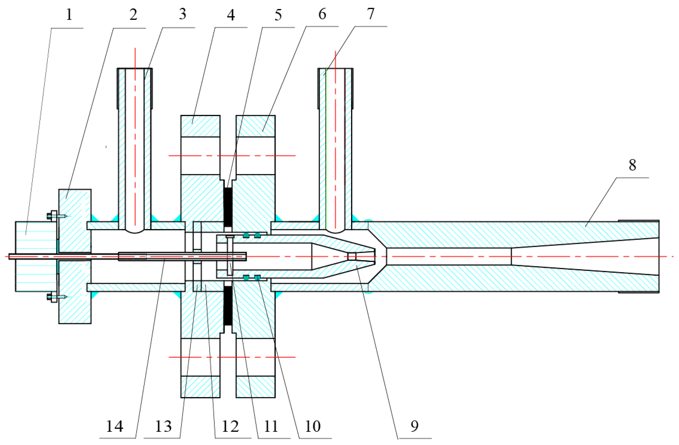
4.1. Structure of Ejector with Automatic Adjustment of Nozzle Exit Position

Considering that screw stepping motor technology is mature and the cost is low, a screw stepping motor is used to adjust the nozzle exit position when designing the automatically adjustable vapor ejector. As shown in Figure 9, the ejector is mainly composed of the screw stepping motor, motor base, high-pressure tee joint, front flange of high-pressure tee joint, flange sealing gasket, rear flange of low-pressure tee joint, low-pressure tee joint, mixing chamber and diffuser, nozzle, nozzle sealing ring, connecting bolt, support ring, hexagonal socket bracket, hexagonal internal thread rod, etc. The motion parameters are regulated through the stepping motor’s operational characteristics, with the directional control achieved by the rotational polarity (clockwise/counterclockwise) and the displacement precision maintained through the number of turns (K) of the stepping motor.
The DONXP is expressed as
D O N X P = x opt D 2
In the stepping motor control system, the relationship between the optimal nozzle exit position and the screw pitch is as follows:
N = x opt L
Therefore, the relationship between the step angle and the number of turns can be further determined:
K = 360 N β

4.2. Automatic Adjustment Method of Nozzle Exit Position Under Variable Working Conditions

Taking R245fa as an example, the automatic control program of the NXP is designed, and the control program flow is shown in Figure 10. After the ejector is manufactured, the nozzle throat diameter Dp0, the mixing chamber diameter D2, the screw pitch L, and the step angle β of the screw stepping motor are all known values. These values can be passed into the register as initialization parameters when writing the automatic control program, allowing the area ratio Ar of the ejector to be calculated. The real-time expansion ratio Ek of the ejector is determined by the measured primary vapor pressure and secondary vapor pressure. Then, the real-time transition point area ratio Arc,k is calculated according to Equation (31). The transition point area ratio Art,k is compared with the ejector area ratio Ar; if Arc,k > Ar, it indicates that when the optimal nozzle exit position is taken, the transition point of the jet should be located after the inlet of the cylindrical mixing chamber. In this case, Equation (35) is used to calculate the real-time optimal dimensionless nozzle exit position DONXPk, whereas if Arc,kAr, Equation (39) is used to calculate the DONXPk. Then, the real-time optimal nozzle exit position xopt,k is calculated through Equation (43). The real-time number of turns Nk required by the stepping motor is calculated through Equation (44), and the real-time pulse number Kk required by the stepping motor is calculated through Equation (45).
The required real-time pulse number Kk obtained is compared with the pulse number Kbef output by the stepping motor last time, and the real-time absolute error ΔKk and real-time relative error ek between Kk and Kbef are calculated. When the instantaneous relative error approaches zero within a negligible threshold, the motor control system remains inactive without generating pulse signals. Conversely, significant deviations require the computational determination of both the pulse polarity and frequency for motor actuation. The specific control process is described as follows: Firstly, assign Kk to Kbef (as the basis for judging whether to perform the motor operation next time). Then, determine the positive and negative values of ΔKk. If ΔKk < 0, it means that the NXP is larger than the optimal nozzle exit position at this time. The output direction should be negative (Y = 1), and the number of pulses should be the absolute value of ΔKk. If ΔKk > 0, it means that the NXP at this time is smaller than the optimal nozzle exit position, taking a positive pulse output (Y = 0).

5. Conclusions

A thermodynamic model for performance prediction of an ejector with an adjustable nozzle exit position is proposed and validated. Based on the model, the main factors affecting the optimal ejector nozzle exit position under variable operating conditions are analyzed. Correlation equations for the optimal dimensionless nozzle exit position under variable operating conditions are then fitted using the R245fa, R134a, R600a, and R141b working fluids, and a strategy for adjusting the ejector nozzle exit position is further derived. The important conclusions obtained include the following:
(1)
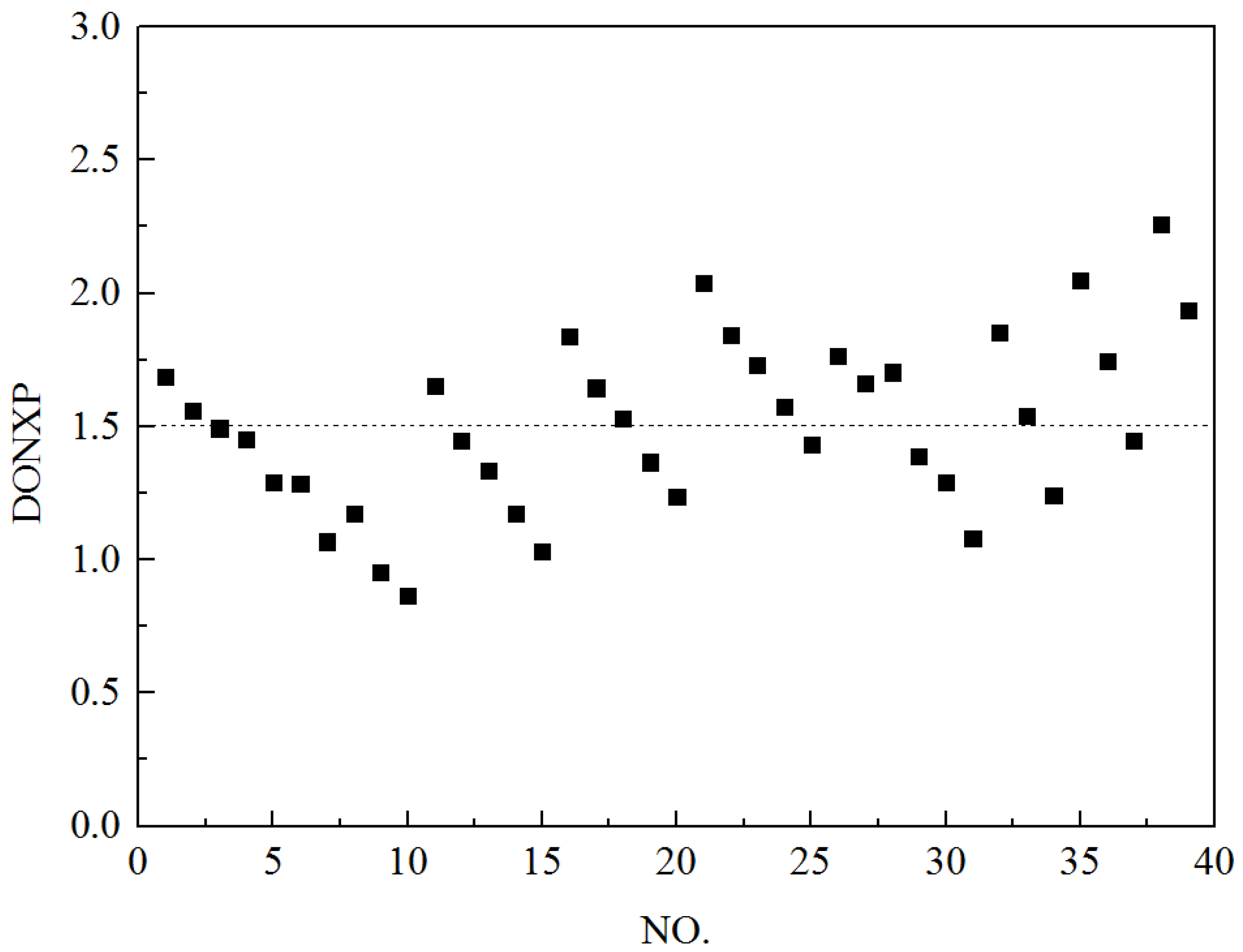
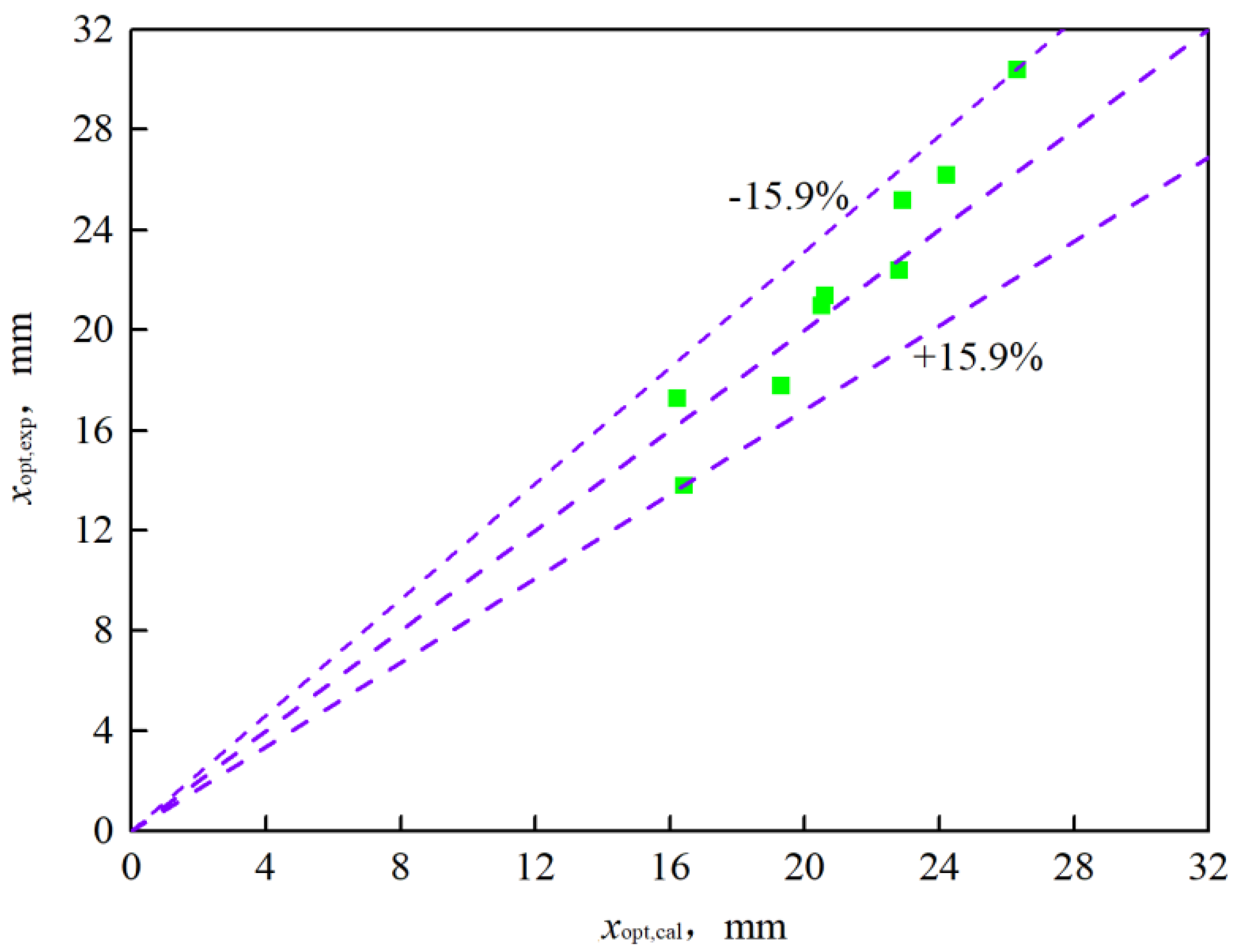
The proposed theoretical model demonstrates reliable accuracy, with the maximum errors in the entrainment ratio, critical back pressure, and nozzle exit position within ±10.70%, ±7%, and ±15.85%, respectively, when compared to the available experimental data.
(2)
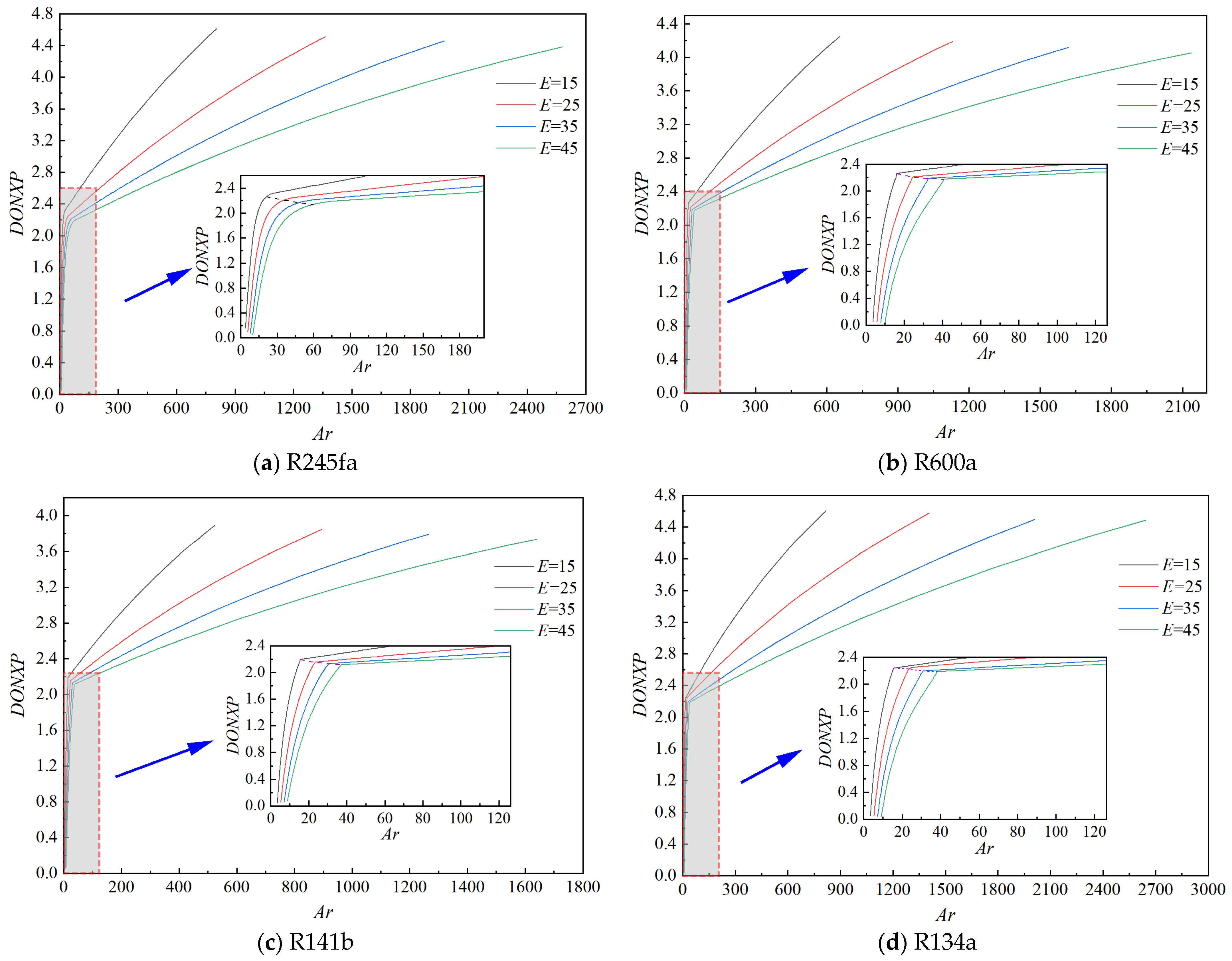
At a certain expansion ratio, the DONXP increases as the area ratio increases. However, there is a transition point in the rate of increase of the DONXP. When the area ratio increases, with the transition point located in the mixing chamber, the increase rates of the DONXP are within 0.068~0.195 for the R245fa, R600a, R141b, and R134a ejectors, whereas with the transition point located before the mixing chamber, the increase rates are within 0.0009~0.0034. Additionally, when the area ratio is fixed, the larger the expansion ratio, the smaller the DONXP.
(3)
The DONXP can be fitted according to different cases where the turning point is located either before or after the entrance of the mixing chamber, resulting in a relational equation associated with the expansion ratio and the area ratio, which can be used for the automatic adjustment of the nozzle exit position.

Author Contributions

H.C. (Hongjie Chen): writing—original draft preparation, funding acquisition; B.C.: methodology, data curation, formal analysis; Z.X.: data curation, visualization, funding acquisition; J.G.: formal analysis; H.C. (Honghua Chen): review and editing, data curation; Z.Z.: software. All authors have read and agreed to the published version of the manuscript.

Funding

This research was supported by the Guangxi Natural Science Foundation under Grant No. 2022GXNSFBA035512, and by the Project for Enhancing Young and Middle-Aged Teacher’s Research Basis Ability in the Colleges of Guangxi under Grant No. 2023KY0825.

Data Availability Statement

The original contributions presented in this study are included in the article. Further inquiries can be directed to the corresponding author.

Conflicts of Interest

The authors declare no conflicts of interest.

Nomenclature

aSpeed of sound, m/s
ACross-sectional area, m2
ArArea ratio
bMixing layer thickness
DDiameter, m
eRelative error
EExpansion ratio
ErEntrainment ratio
hSpecific enthalpy, kJ/kg
KNumber of pulses driving stepping motor
LScrew pitch, m
m ˙ Mass flow rate, kg/s
MConvective Mach number
NNumber of motor turns
pPressure, Pa
RRadius, m
uRadial velocity
vSpecific volume, m3/kg
wAxial velocity
sSpecific entropy, kJ/(kg·K)
TTemperature, K
xValue of nozzle exit position, m
YCriterion for controlling pulse direction
Greek letters
βStep angle of stepping motor, °
ηIsentropic efficiency
μMomentum efficiency
ρDensity, kg/m3
ψCross section coefficient
ΦCompressibility factor
Subscripts
befPrevious calculated value
cValue of turning point
criCritical value
calCalculated value
choValue of double-choking mode
dMixed vapor
d4Mixed vapor on cross section 4
expExperimental value
iParameter of inner boundary of mixing layer
isParameter after isentropic process
kLoop count
mParameter on axis
oParameter of external boundary of mixing layer
optOptimal value
pPrimary vapor
p0Parameter of primary vapor on cross section 0
p1Parameter of primary vapor on cross section 1
sSecondary vapor
s1Parameter of secondary vapor on cross section 0
0Parameter on cross section 0
1, 2, 3, 4Parameter on cross sections 1, 2, 3, 4
Abbreviations
CFDComputational fluid dynamics
DONXPDimensionless optimal nozzle exit position
NXPNozzle exit position

References

  1. Fingas, R.; Haida, M.; Smolka, J.; Croci, L.; Bodys, J.; Palacz, M.; Besagni, G. Experimental analysis of the r290 variable geometry ejector with a spindle. Appl. Therm. Eng. 2025, 258, 124632. [Google Scholar] [CrossRef]
  2. Li, W.; Han, Q.; Wang, C.; Zhang, H.; Jia, L.; Wang, L.; Sun, W.; Xue, H. Influence of geometric parameters on ejector acoustics and efficiency in ejector refrigeration system. Int. J. Refrig. 2025, 169, 429–443. [Google Scholar] [CrossRef]
  3. Dai, Z.; Li, B.; Elbel, S. Advances in ejector research for multi-effect thermal vapor compression desalination. Renew. Sustain. Energy Rev. 2025, 208, 115010. [Google Scholar] [CrossRef]
  4. Fu, W.; Liu, Z.; Li, Y.; Wu, H.; Tang, Y. Numerical study for the influences of primary steam nozzle distance and mixing chamber throat diameter on steam ejector performance. Int. J. Therm. Sci. 2018, 132, 509–516. [Google Scholar] [CrossRef]
  5. Ramesh, A.S.; Sekhar, S.J. Experimental and numerical investigations on the effect of suction chamber angle and nozzle exit position of a steam-jet ejector. Energy 2018, 164, 1097–1113. [Google Scholar] [CrossRef]
  6. Metin, C.; Gök, O.; Atmaca, A.U.; Erek, A. Numerical investigation of the flow structures inside mixing section of the ejector. Energy 2019, 166, 1216–1228. [Google Scholar] [CrossRef]
  7. Eldakamawy, M.H.; Sorin, M.V.; Brouillette, M. Blowdown experimental study on butene ejector. Appl. Therm. Eng. 2019, 160, 114000. [Google Scholar] [CrossRef]
  8. Han, Y.; Wang, X.; Sun, H.; Zhang, G.; Guo, L.; Tu, J. CFD simulation on the boundary layer separation in the steam ejector and its influence on the pumping performance. Energy 2019, 167, 469–483. [Google Scholar] [CrossRef]
  9. Geng, L.; Cao, H.; Meng, Q.; Li, J.; Jiang, P. Effects of operating conditions and geometries on the performance of nitrogen ejectors for joule–thomson cooling. Appl. Therm. Eng. 2022, 212, 118557. [Google Scholar] [CrossRef]
  10. Chen, H.; Zhu, J.; Ge, J.; Lu, W.; Zheng, L. A cylindrical mixing chamber ejector analysis model to predict the optimal nozzle exit position. Energy 2020, 208, 118302. [Google Scholar] [CrossRef]
  11. Poirier, M. Influence of operating conditions on the optimal nozzle exit position for vapor ejector. Appl. Therm. Eng. 2022, 210, 118377. [Google Scholar] [CrossRef]
  12. Wang, C.; Wang, L.; Wang, X.; Zhao, H. Design and numerical investigation of an adaptive nozzle exit position ejector in multi-effect distillation desalination system. Energy 2017, 140, 673–681. [Google Scholar] [CrossRef]
  13. Chen, Z.; Zhao, H.; Kong, F.; Liu, G.; Wang, L.; Lai, Y. Synergistic effect of adjustable ejector structure and operating parameters in solar-driven ejector refrigeration system. Sol. Energy 2023, 250, 295–311. [Google Scholar] [CrossRef]
  14. Rand, C.P.; Croquer, S.; Poirier, M.; Poncet, S. Optimal nozzle exit position for a single-phase ejector (experimental, numerical and thermodynamic modelling). Int. J. Refrig. 2022, 144, 108–117. [Google Scholar] [CrossRef]
  15. Zhou, Y.; Chen, G.; Hao, X.; Gao, N.; Volovyk, O. Working mechanism and characteristics analysis of a novel configuration of a supersonic ejector. Energy 2023, 278, 128010. [Google Scholar] [CrossRef]
  16. Zheng, L.; Deng, J.; He, Y.; Jiang, P. Dynamic model of a transcritical CO2 ejector expansion refrigeration system. Int. J. Refrig. 2015, 60, 247–260. [Google Scholar] [CrossRef]
  17. Han, H. Jet Theory and Its Application; Zhejiang University Press: Hangzhou, China, 1990. [Google Scholar]
  18. Van den Berghe, J.; Dias, B.R.B.; Bartosiewicz, Y.; Mendez, M.A. A 1d model for the unsteady gas dynamics of ejectors. Energy 2023, 267, 126551. [Google Scholar] [CrossRef]
  19. Sokolov, E.Y.; Zinger, N.M. Jet Devices; Energoatomizdat: Moscow, Russia, 1989. [Google Scholar]
  20. Ren, J.; Zhao, H.; Wang, M.; Miao, C.; Wu, Y.; Li, Q. Design and investigation of a dynamic auto-adjusting ejector for the med-tvc desalination system driven by solar energy. Entropy 2022, 24, 1815. [Google Scholar] [CrossRef]
  21. Huber, M.L.; Lemmon, E.W.; Bell, I.H.; Mclinden, M.O. The nist refprop database for highly accurate properties of industrially important fluids. Ind. Eng. Chem. Res. 2022, 42, 15449–15472. [Google Scholar] [CrossRef]
  22. Gatski, T.B.; Bonnet, J. Compressibility, Turbulence and High Speed Flow; Academic Press: Oxford, UK, 2009. [Google Scholar]
  23. Yi, S.; Zhao, Y.; He, L. Supersonic and Hypersonic Nozzle Design; National Defence Industry Press: Beijing, China, 2013. [Google Scholar]
  24. Huang, B.J.; Chang, J.M.; Wang, C.P.; Petrenko, V.A. A 1-d analysis of ejector performance. Int. J. Refrig. 1999, 22, 354–364. [Google Scholar] [CrossRef]
  25. Shestopalov, K.O.; Huang, B.J.; Petrenko, V.O.; Volovyk, O.S. Investigation of an experimental ejector refrigeration machine operating with refrigerant r245fa at design and off-design working conditions. Part 2. Theoretical and experimental results. Int. J. Refrig. 2015, 55, 212–223. [Google Scholar] [CrossRef]
  26. Valle, J.G.D.; Jabardo, J.M.S.; Ruiz, F.C.; Alonso, J.F.S.J. An experimental investigation of a r-134a ejector refrigeration system. Int. J. Refrig. 2014, 46, 105–113. [Google Scholar] [CrossRef]
  27. Butrymowicz, D.; Śmierciew, K.; Karwacki, J.; Gagan, J. Experimental investigations of low-temperature driven ejection refrigeration cycle operating with isobutane. Int. J. Refrig. 2014, 39, 196–209. [Google Scholar] [CrossRef]
Figure 1. Structure of ejector.
Processes 13 00879 g001
Figure 2. The mixing layer in the ejector.
Processes 13 00879 g002
Figure 3. The flow chart of the performance calculations.
Processes 13 00879 g003
Figure 4. The relative errors of the entrainment ratio.
Processes 13 00879 g004
Figure 5. The relative errors of the critical back pressure.
Processes 13 00879 g005
Figure 6. Distribution of DONXP for 141b ejector.
Processes 13 00879 g006
Figure 7. The relative error of the optimal nozzle exit position for the R245fa ejector.
Processes 13 00879 g007
Figure 8. The relationship between the area ratio and the DONXP for the ejectors with different expansion ratios under off-design conditions.
Processes 13 00879 g008
Figure 9. Structure of ejector with axially adjustable nozzle. 1. Screw stepping motor. 2. Motor base. 3. High-pressure tee joint. 4. Front flange of high-pressure tee joint. 5. Flange sealing gasket. 6. Rear flange of low-pressure tee joint. 7. Low-pressure tee joint. 8. Mixing chamber and diffuser. 9. Nozzle. 10. Nozzle sealing ring. 11. Connecting bolt. 12. Support ring. 13. Hexagonal socket bracket. 14. Hexagonal internal thread rod.
Processes 13 00879 g009
Figure 10. Flow chart of program for ejector with electronically regulated nozzle exit position.
Processes 13 00879 g010
Disclaimer/Publisher’s Note: The statements, opinions and data contained in all publications are solely those of the individual author(s) and contributor(s) and not of MDPI and/or the editor(s). MDPI and/or the editor(s) disclaim responsibility for any injury to people or property resulting from any ideas, methods, instructions or products referred to in the content.

