Article

CFD Simulation Analysis of a Diesel Generator Exhaust Muffler and Performance-Based Optimization

by
Kursat Tanriver
Department of Mechatronics Engineering, Faculty of Engineering and Natural Sciences, Istanbul Health and Technology University, 34445 Istanbul, Turkey
Processes 2025, 13(3), 887; https://doi.org/10.3390/pr13030887
Submission received: 17 February 2025 / Revised: 12 March 2025 / Accepted: 14 March 2025 / Published: 18 March 2025
(This article belongs to the Section Energy Systems)

Abstract

:
This study addresses a gap in the literature by simultaneously optimizing noise reduction and structural integrity in silencer design. A novel silencer model offering advantages over conventional designs was developed. In the first phase, the initial optimization model was developed to minimize noise levels while considering environmental constraints. CFD analyses using NEC Acostix and Ex-Tuner calculated noise, temperature, and pressure, followed by validation in SimScale. The results demonstrated improved efficiency in reducing pressure loss and noise. A silencer with Ø 800 mm diameter, 3000 mm length, and Ø 355.6 mm exhaust connection was manufactured and tested, achieving 96 dB(A) at 1 m, with front and side measurements of 85.1 dB(A) and 74.4 dB(A), respectively. In the second phase, fastener durability in silencer support plates was optimized using tensile tests and FEA in Ansys R19.2. Parametric analyses for M4-M20 bolts were conducted, and regression analysis in Minitab (Minitab Statistical Software Version 21.1) showed 97.74% accuracy. An objective function was developed using curve fitting. The second optimization problem, incorporating design constraints, was solved using the interior-point and Lagrange multipliers methods. This study provides a foundation for silencer design, ensuring both structural reliability and noise control. Future research will explore performance eco-friendly solutions across varying generator power levels.

1. Introduction

Today, there is a need for electrical energy in every aspect of our lives. This need is often met through the use of diesel generators due to their low investment cost, ease of use, and the advantage of being compatible with other energy sources.
Diesel generators are widely used in various locations such as heavy industrial facilities, residential buildings, hotels, municipalities, hospitals, and data centers, where containerized emergency generators are preferred. To ensure that generator installations, including diesel generators, do not have a negative impact on human health and the environment, there are specific regulations and guidelines that must be followed [1].
Silencers (or mufflers) are among the primary equipment used to minimize these negative effects in diesel generators. While the fundamental function of silencers is to expel exhaust gasses from the engine [2,3] and reduce noise levels [4,5], achieving the desired efficiency requires maintaining an appropriate exhaust gas pressure to ensure proper combustion in the cylinder chamber [6,7]. Silencers primarily reduce noise levels by altering the flow of sound waves or trapping them within noise-absorbing materials [8,9,10,11,12]. In most cases, silencers are composed of an expansion chamber, perforated pipes, and a tubular metal casing. Before the exhaust gasses are released into the atmosphere, they are attenuated within the silencer based on the fundamental physical principle of noise cancelation. The purpose of noise suppression is to reduce the noise emitted into the environment to a lower level [13]. A schematic representation of a diesel generator equipped with a silencer is shown in Figure 1 [14].
Various literature studies have been conducted for the design, some of which are given below.
Studies related to noise measurement and sound transmission are as follows. In the study conducted by Li et al. [15], a simplified experiment was performed to measure the noise reduction effect of the silencer and evaluate the accuracy of the theoretical prediction method. They reported that low-frequency silencers can provide more compact and flexible noise reduction compared to traditional reactive silencers. Archana and Surve [16] presented an algorithm that can generate results quickly from data for the ideal measurement of transmission loss of a silencer in a laboratory environment. Dogra et al. [17] have presented a comprehensive study using numerical, experimental, and theoretical methods to evaluate the sound transmission loss within the re-air duct. They used a four-microphone impedance tube technique to measure sound transmission loss. The findings revealed that the study led to a significant reduction in noise measurement throughout the air duct. Rahmani et al. [18] constructed an expansion silencer. This silencer could effectively reduce noise produced by compressors. In their study, sound transmission loss of the silencers was measured using an impedance tube. The results of the modeling showed that increasing the diameter of the silencer leads to an increase in transmission loss at all frequencies. Villau et al. [19] studied a new compact silencer. This novel silencer concept was proposed together with the respective acoustic characteristics, experimentally determined in the dedicated test stands, including the transmission loss and the reflection and absorption properties. Fu et al. [20] conducted start-up experiments and load mutation experiments for a diesel engine using a MATLAB (R2022b, academic use)/Simulink simulation model. Subsequently, they imposed measurement of noise and process noise.
In addition to acoustic studies, research on exhaust emissions and environmental impacts includes the following. Kan and Yang [21] analyzed the effect of changes in the junction geometry of an exhaust pipe system on backpressure and exhaust emissions. Their findings indicated that the H-type exhaust pipe system exhibited the highest pressure due to the influence of junction geometry, leading to the highest measured levels of harmful gasses affecting the environment. Conversely, the X-type exhaust pipe system demonstrated the lowest pressure, resulting in the lowest recorded emission values. Consequently, the study proposed an optimized exhaust system to reduce harmful gas emissions and confirmed the significance of backpressure in exhaust system design. Li et al. [22] proposed a parallel perforated pipe expansion silencer and conducted a numerical analysis of its acoustic and aerodynamic performance using the finite element method. Through optimization results, they successfully reduced exhaust noise and improved the engine’s fuel economy. Li et al. [23] investigated gasoline, diesel, and hybrid engines to enhance exhaust emission efficiency. Wansom et al. [24] examined the removal efficiency of particulate matter smaller than 2.5 microns (PM2.5) in a diesel engine using an innovative wet scrubber tower. They reported that the designed wet scrubber tower could purify up to 13,320 m3 of air per day or remove up to 2464 g of PM2.5 daily. Mikky et al. [25] developed two mathematical models: the first aimed to predict the nanoparticle properties in any diesel-biodiesel-nanoparticle blend, while the second sought to maximize the biodiesel ratio in biodiesel-diesel-nanoparticle mixtures.
Studies that integrate acoustic research with Computational Fluid Dynamics (CFD) analysis include the following. Ma et al. [26] conducted a study to identify the critical components of the acoustic field in a piston-type pressure reduction valve with a high-pressure reduction ratio and to predict adverse noise both experimentally and numerically. Numerical calculations were performed using a hybrid approach that combined computational fluid dynamics (CFD) and computational aeroacoustics (CAA). This study provided new insights into the role of each component in flow-induced noise, offering an academic perspective on noise reduction and optimization. Zhang, S.-W. et al. [27] investigated flow-induced acoustic-vibration characteristics and noise reduction methods in elbows. Their simulations demonstrated that increasing thickness and elbow radius while reducing the elbow angle effectively decreased noise levels. Additionally, they reported that the use of elastic supports and damping materials could reduce elbow noise by at least 26.3%. Alexanda Petrovic et al. [28] evaluated the effects of variations in flue gas temperature, absorber column operating pressure, exhaust gas recirculation rate, and amine concentration using signal-to-noise ratios and variance analysis. Their findings indicated that all examined factors, except for flue gas temperature, had a statistically significant relationship with the response. Yadav et al. [13] designed a silencer model with a rectangular chamber. The CFD analysis results revealed a proportional relationship between static pressure and transmission loss. Tanrıver and Ay [29] conducted a CFD analysis on a refuse chute pipe, demonstrating that viruses could be transported to other floors via airflow. Subsequently, they integrated CFD analysis with optimization methods to propose an optimal design model that meets system requirements.
Studies using experimental and finite element methods in connection elements are as follows. Binh Pham, Hung Pham, and Hancock [30] conducted shear experiments on bolted connections between thin and thick plates and compared their strength properties. Li et al. [31] studied the dynamic and mechanical behavior of a rotor-bearing system with a bolted connection structure. The characteristics of the base looseness error occurring in a bolted connection rotor system were investigated by comparing the variation ranges of the bending stiffness and dynamic responses. Cheng et al. [32] created a finite element model for the riveting process and developed a dual-robot pneumatic riveting cell for body panel assembly to obtain experimental results. They showed that the developed method has good performance. Tanriver and Ay [33] examined how variations in flue gas temperatures following combustion influence rivet design. To achieve this, they employed both experimental and analytical approaches to optimize fasteners with varying diameters. Kong et al. [34] investigated the fracture damage of particle reinforced composites and the related effect on their mechanical properties. Based on the tensile test results of these materials, the parameters of the macro-elastic-plastic finite element model and the micro-particle reinforced model were obtained. Yi et al. [35] studied the mechanical performance of single shear bolted connections. They offered ease of installation without the need for specialized tools. He et al. [36] developed this to connect steel frames. In their study, two high-strength bolts were attached to the upper anchor plate installed in the opening and the bottom anchor plate placed below the top flange of the steel beam. As a result of tests on blind bolts, Gao et al. [37] suggested practical calibration, real-time monitoring, and periodic detection processes, taking into account the application in the real construction site.
As observed in the aforementioned studies, muffler-related research spans noise reduction, pressure drop, optimal design, CFD analysis, and optimization. However, no existing study has simultaneously addressed noise reduction, pressure drop, CFD-based optimization, and structural optimization. Responding to this gap, the present manuscript introduces two optimization models. The first optimization model focuses on balancing noise reduction and pressure drop; to this end, CFD-based flow and noise analyses were performed using NEC Acostix and Ex-Tuner software, supplemented by validation analyses in SimScale. The second optimization model aims to enhance the mechanical strength of the muffler’s support plates. Validation was conducted by performing tensile tests on ten samples with M12 bolts and verifying these results using ANSYS FEM analyses. Following validation, parametric and regression analyses of the designed muffler support plates were carried out to formulate an objective function. Constraints reflective of the muffler’s operating conditions were then defined, and an optimization tool based on the interior point and Lagrange multiplier methods was developed in MATLAB.
In addition to presenting two optimization models simultaneously, this work contributes further novelty through the development of the Novel Designed Silencer. Separate CFD analyses were conducted for both the Conventional Silencer and the Novel Designed Silencer. Field measurements were performed to confirm whether the Novel Designed Silencer satisfies operational requirements, and these tests demonstrated that the new design meets the specified criteria. Through these comprehensive innovations, this study offers a solution to professionals, researchers, and readers by addressing both structural design and computational system requirements in a manner that promotes time savings, efficiency, and practical implementation.

2. Materials and Methods

2.1. Material

A two-chamber silencer with a single inlet and outlet was modeled for use in CFD and field studies. In this model, a silencer design was implemented for a Perkins 4008-30TAG3 engine with an electrical power output of 1105 kW.
The silencer design incorporates a perforated pipe structure to investigate the stress distribution, noise reduction, and vibration characteristics of a silencer exposed to high-temperature and high-pressure exhaust gasses. The silencer body was manufactured using 3 mm ST 37 plate steel. Inside the body, a 100 mm thick layer of mineral wool with a density of 80 kg/m3 was used, covered with a 1 mm perforated sheet. The silencer model is presented in Figure 2, and its specifications are provided in Table 1.
For the study on the bolts used in the silencer support, a set of experiments has been prepared. For this purpose, ten test specimens with identical type and characteristics were prepared.
Usually, to study the shear stresses on bolts, two or more plate-fixed samples are prepared. Force is applied to the plates by adhering to the rules, specifications of the tensile device, and laboratory conditions. Thus, the bolts between the plates are subjected to shear stress. The data presented here, along with the silencer design, were utilized in the preparation of the test set. The procedure for the prepared test sample is illustrated in Figure 3 [38]. Silencers are fixed to the container body with plates on the support.
To support the weight of the silencers, the bolts connecting the two plates are subjected to shear forces. In this study, considering the generator installation environment, 8.8-grade hexagonal-headed bolts with a zinc coating were chosen to enhance corrosion resistance under outdoor conditions. Taking into account real field conditions and the capacity of the testing apparatus, ten identical test specimens were prepared to ensure the reliability and repeatability of the experiments.
The prepared test sample is designed to fit the tensile testing device, with dimensions of 100 mm in width and 120 mm in length. Each sample consists of a 12 mm thick ST 37 plate, and M12 zinc-coated steel bolts, 50 mm in length, were used for the connections. The selected bolts are fully threaded, hexagonal-headed, and comply with the DIN 933 standard.

2.2. Method

Various software programs equipped with CFD analysis modules are available for simulating fluid flow inside pipes and silencers [33,34]. In this study, the SimScale computational fluid dynamics (CFD) analysis software was chosen due to its accuracy in handling turbulent flow conditions and its compatibility with large-scale industrial applications. The mathematical calculations were based on the Reynolds-Averaged Navier–Stokes (RANS) equations, which were examined in detail.
To improve accuracy, a mesh refinement study was conducted to determine the optimal grid size. The meshing process utilized tetrahedral and hexahedral elements to balance computational efficiency and solution accuracy. The boundary conditions were set as follows; the inlet was defined with a velocity inlet condition based on actual engine exhaust parameters, while the outlet was assigned a pressure-outlet boundary condition. The k-ε turbulence model was implemented due to its proven reliability in predicting turbulent flows within confined geometries.
To calculate the sound levels based on the given sound requirements of the Perkins 4008-30TAG3 engine with an electrical power of 1105 kW, both empirical and computational noise calculations were employed. The noise simulations were performed using the NEC Acostix and Ex-Tuner sound calculation software, licensed by Özer Elektrik. NEC Acostix complies with the ISO 14163:1998 [39] Guidelines for Noise Control by Silencers standard, while Ex-Tuner follows the sizing, performance, and restriction rules specified in ASHRAE TC 2.6: 2011. After these calculations, the designed silencers underwent experimental validation through noise measurements in an open installation area using standardized sound level meters. For the noise measurements, the CEM DT-805/805L noise measurement device was used, which conforms to IEC 60651:2001 and EN60651:1994 standards [40]. Noise measurements were taken at multiple locations around the silencer to account for variations in sound propagation.
The silencers were manufactured in accordance with EN 1090-1 [41] (Assessment-verification of constancy of performance for structural components) and EN ISO 3834-2 [42] (Quality requirements for fusion welding of metallic materials) standards. The widely recognized international standards for tensile testing of metal materials include ISO 6892-1:2016 and ASTM E8:2016 [39]. To ensure experimental consistency, all test specimens were manufactured under identical conditions and dimensions. In this study, the experimental setup was designed in compliance with the ISO 6892-1:2016 [43] standard to evaluate the performance of an M12-diameter bolt under varying forces.
Before conducting the experiment, the Instron 5569 tensile testing device was calibrated, and all necessary adjustments and control mechanisms were carefully checked to minimize potential errors during testing. For the experiment, ten identical test specimens were prepared. Each specimen consisted of two stacked ST 37 plates, each 12 mm thick, securely fastened at the center using a zinc-coated M12 bolt. The bolt’s preload force was applied using a controlled torque method to ensure uniform initial conditions.
For each test, the tensile load was increased incrementally at a rate of 2 mm/min at room temperature until the bolt experienced shear failure. Throughout the test, displacement data were recorded using a high-precision digital extensometer. To validate the experimental findings, as commonly conducted in similar studies, finite element analysis (FEA) was performed alongside tensile testing [44]. The FEA was carried out using the Structural Analysis module of ANSYS R19.2 software, focusing on the evaluation of shear stresses [45].
The numerical model incorporated material properties extracted from the experimental stress–strain curves to enhance accuracy. Contact interactions between the bolt and the plates were modeled using frictional contact elements, ensuring realistic load transfer simulations.

3. Result and Discussion

The components of a generator set, including a radiator, diesel engine, and alternator, generate noise at various frequencies and amplitudes. To mitigate the noise, exhaust silencer designs play a crucial role. In research studies, the transmission loss values of silencers are calculated in 1/3 octave bands to meet the specific noise reduction requirements [46].
In this model, the exhaust silencer design for the Perkins 4008-30TAG3 diesel engine with an electrical power of 1105 kW has been developed. The 1/3 Octave Analysis data provided by the manufacturer for the exhaust system has been utilized for the design process. The Diesel engine data used in the design are presented in Table 2 [47] and the noise and frequency graphs used in the design are presented in Figure 4 [47].

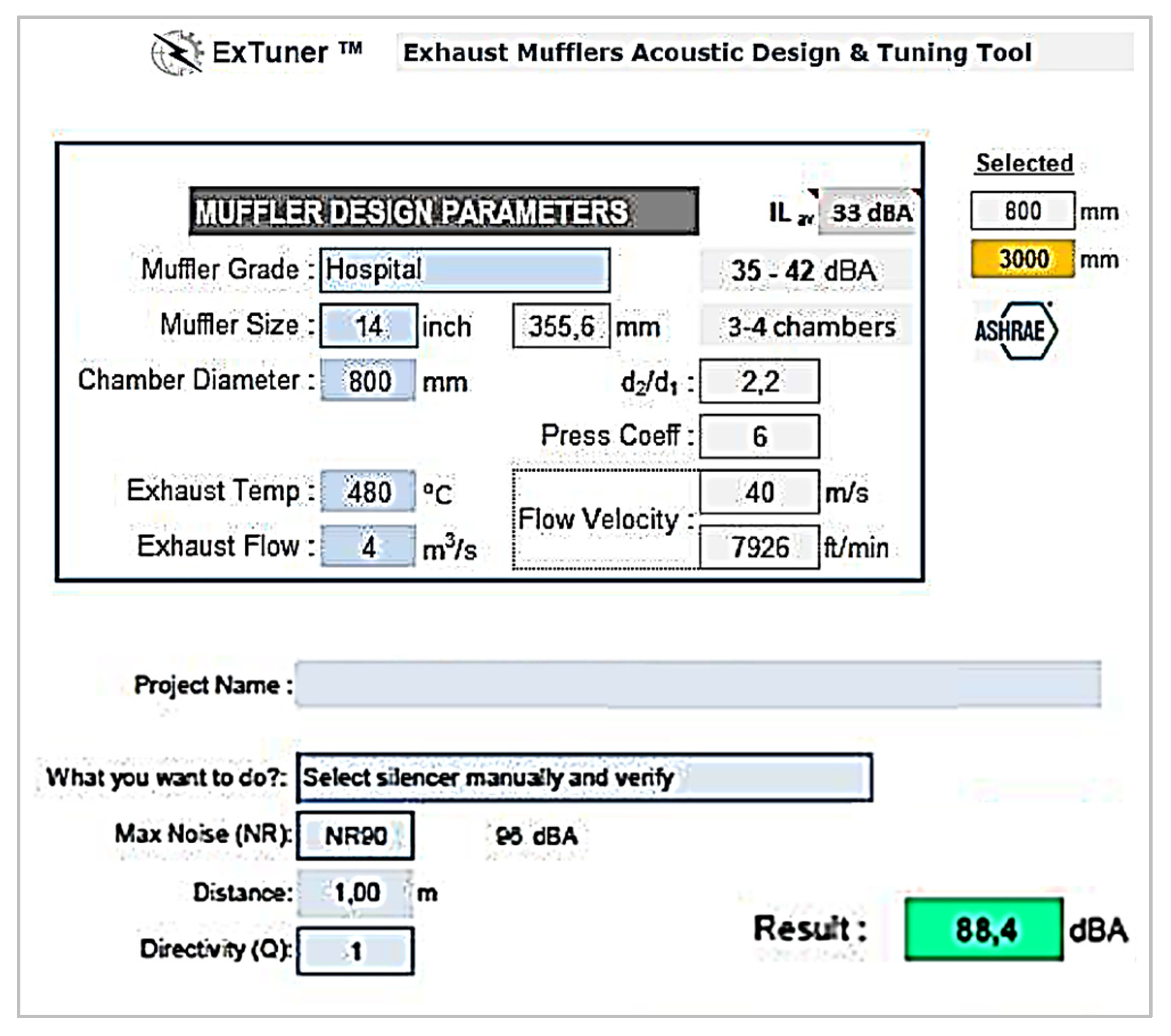
3.1. Mathematical Modeling
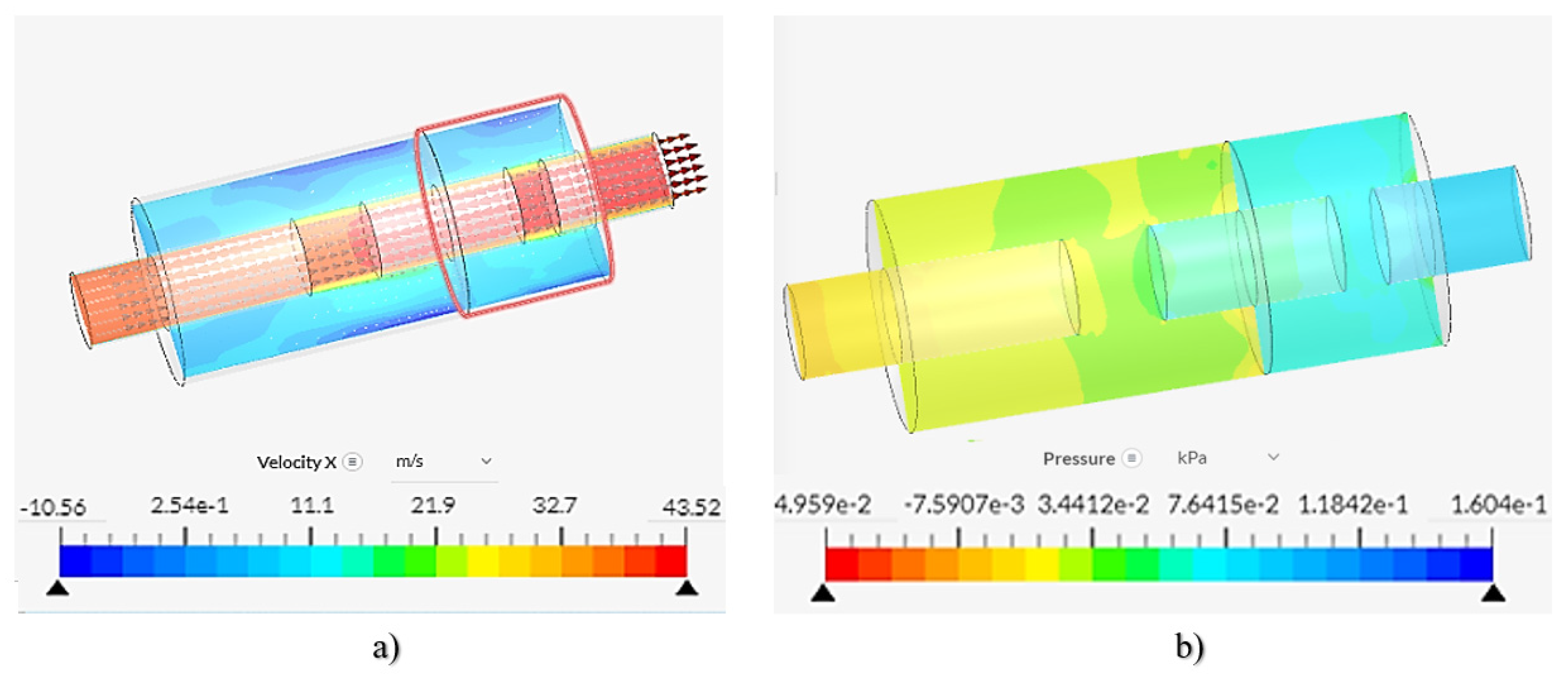
In this study, the realizable method, which is applicable for CFD analysis calculations, is used in conjunction with the Reynolds-Averaged Navier–Stokes (RANS) method. The k-ε model, an improved version of the classical model, was selected due to its enhanced ability to simulate thermal effects with an advanced wall treatment. This model is known for its effectiveness in complex flow conditions and for providing a more accurate heat distribution through the (ε) equation.
The realizable k-ε model is particularly recognized for its superior performance in predicting the behavior of both planar and circular jet flows [48]. To understand the regions where turbulence is concentrated within the silencer, the continuity, momentum, and energy equations, which govern the flow, are provided in Equations (1), (2), and (3), respectively [49].
The continuity equation, which ensures the conservation of mass in the silencer system, is given as follows:
p t + . ρ V = 0
This section examines the distribution of fluid density (ρ ρ ) and velocity (v) throughout the defined control volume, based on the principle of mass conservation within the muffler. As a result, it verifies that mass inflows and outflows are balanced at any cross-section of the muffler.
The momentum equation governs the motion of the exhaust gasses inside the silencer and is given by
p t ρ v + . ρ v v = p + . μ v + v T
This section illustrates how exhaust gasses accelerate or decelerate within the muffler. As the flow interacts with wall surfaces and any potential flow-directing elements, inertial forces, pressure gradients, viscous forces, and turbulence stresses are taken into account.
The energy equation, which governs the heat transfer within the silencer due to exhaust gas flow, is given by
ρ c p t + ρ c v . T . λ T ] = 0
This section explains how the heat carried by the exhaust gasses interacts with both the solid surfaces inside the muffler and the flow itself. Accurate prediction of heat transfer is of particular importance for diesel generator exhaust systems operating at high temperatures, as it directly influences both flow behavior and muffler design.
The fundamental equation for three-dimensional incompressible turbulent flows using the realizable k-ε turbulence model is given as follows:
k t + x j   ρ u j k = x j   μ + μ t σ k k x j + G k + G b   ρ ε Y M + S k
The turbulence dissipation rate equation in the realizable k− ϵ model is given as
ε t + x j   ρ u j ε = x j   μ + μ t σ ε ε x j + C 1 S ε C 2 ρ ε 2 K + ν ε + C 1 ε k C 3 G b + S ε
Parameter definitions for the k−ϵ turbulence model are as follows:
P—Fluid density (kg/m3)
V—Velocity vector (m/s)
p—Pressure (Pa)
μ—Dynamic viscosity (Pa·s)
T—Temperature (K)
Λ—Thermal conductivity (W/mK)
c—Specific heat capacity (J/kgK)
k—Turbulent kinetic energy (m2/s2)
ϵ—Turbulence dissipation rate (m2/s3)
ν—Kinematic viscosity (m2/s)
Gk—Turbulent kinetic energy production term
Gb—Turbulence production due to buoyancy forces
YM—Turbulence loss due to compressibility effects
Sk—Source term for turbulent kinetic energy
Sϵ—Source term for turbulence dissipation rate
These parameters are essential for accurately modeling turbulent flow behavior in CFD simulations, particularly when using the realizable k−ϵ turbulence model.
The Realizable k–ε model is preferred over the classical k–ε approach due to its improved wall treatment and superior predictions in flow fields characterized by high velocity gradients. In the numerical solution process, the muffler geometry is initially divided using a suitable mesh to more accurately capture regions of significant turbulence. At the inlet, the exhaust gas flow rate and temperature profile are defined, while the outlet is set at atmospheric pressure. The no-slip boundary condition on the walls, together with appropriate heat transfer modeling, enables a realistic representation of thermal interactions. By employing the Reynolds-Averaged Navier–Stokes (RANS) approach alongside pressure–velocity coupling algorithms, the interactions among velocity, pressure, and turbulence variables can be resolved with high accuracy. The Realizable k–ε model’s definitions for turbulent kinetic energy (k), turbulence dissipation (ε), and associated production/dissipation terms (Gk, Gb, YM, etc.), along with additional source terms (Sk, Sε), enable a detailed analysis of flow and heat transfer, leading to a more realistic evaluation of the muffler’s performance under operating conditions.

3.2. CFD Modeling

NEC Acostix and Ex-Tuner sound calculation software conduct CFD analysis by evaluating flow parameters such as temperature, pressure, and noise levels. Based on these calculations, an optimized silencer design with an appropriate cross-section for the diesel generator was developed, as illustrated in Figure 5. Consequently, the silencer design was initially formulated through preliminary calculations before conducting the CFD analysis in the SimScale software.
The preliminary cross-sectional design calculation of the silencer was conducted using the NEC Acostix and Ex-Tuner sound calculation software [50] to achieve a target sound level of 96 dB(A) at a distance of 1 m. The resulting cross-sectional design of the silencer is presented in Figure 6.
Based on this calculation, a silencer was designed, with its manufacturing stages illustrated in Figure 7. According to the sound calculation, the silencer chamber has a diameter of Ø 800 mm, a length of 3000 mm, and an exhaust connection diameter of Ø 355.6 mm. Additionally, the flow velocity was determined to be 40 m/s. These parameters were incorporated into the flow simulation for further analysis.
Flow analysis simulations were conducted for both the conventionally used and newly designed silencers, considering their internal structures. The SimScale software was utilized for these simulations, employing the Reynolds-Averaged Navier–Stokes (RANS) equation approach for the analysis.
Figure 8 presents the flow analysis simulation of the conventionally used silencer. In this design, the pressure drop was measured at 0.160 kPa (p1). A hex-dominant meshing approach was applied, utilizing 250,800 nodes and 83,573 hexahedral elements. Although the pressure drop in this design is within an acceptable range, it fails to meet the required noise level standards. Consequently, the newly designed silencer must ensure compliance with both the feedback pressure and noise level requirements of the diesel engine.
The flow analysis simulation of the newly designed silencer is presented in Figure 9. In this design, the maximum pressure drop was recorded as 6.149 kPa (approximately 6.15 kPa). A nominal hex-dominant meshing approach was employed, with the mesh process incorporating 256,990 nodes and 99,681 hexahedral elements.
The newly designed silencer and the exhaust pipeline, as shown in Figure 2, must comply with the total back pressure requirements of the diesel engine. To ensure this, calculations were performed following the EN 13384-1 [51] standard for heat and fluid dynamics. The corresponding calculations are presented in the following equations.
p = p 1 + p 2
p 2 = s Ψ   l D + 1 n ξ n ρ m w m 2 2
p p b
Based on the given parameters—s = 1.5, Ψ = 0.40 (pipe friction coefficient), L = 1.0 m (pipe length), D = 0.355 m (pipe diameter), ξn = 0.35 (total pipe resistance), ρm = 0.765 kg/m3 (flue gas density), wm = 40 m/s, p1 = 6.15 kPa, and p2 = 0.48 kPa—the total back pressure was calculated as Ʃp = 6.63 kPa.
According to the established equations, the condition 6.63 kPa ≤ 7 kPa (exhaust back pressure limit, pb) is satisfied, confirming that the designed system meets the required back pressure constraints.

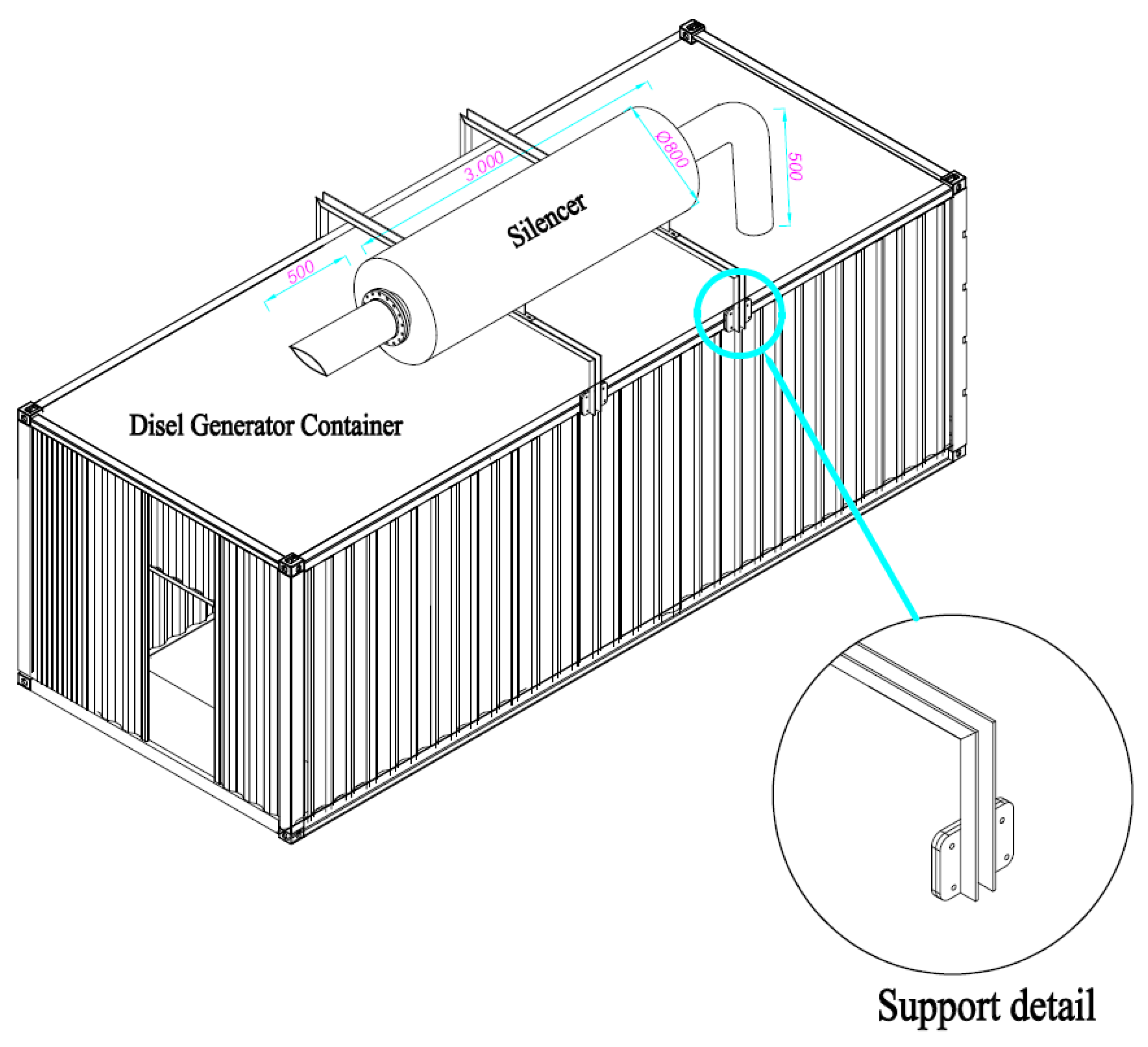
3.3. Case Study: Industrial Implementation of the Novel Silencer Design

Field tests were conducted in an industrial environment to validate the performance of the silencer design under real operating conditions. Noise measurements were taken at the front and lateral sides of the generator, set during operation. Experimental measurements were carried out using calibrated sound level meters deployed on-site. Once the required pressure conditions were confirmed, noise levels were recorded.
The silencer was manufactured and installed onto the container, and noise measurements were performed while the generator inside the enclosure was in operation. Measurements were taken at a distance of 1 m from both the front and the critical left side of the enclosure. The recorded noise levels were 85.1 dB(A) at 1 m from the front and 74.4 dB(A) at 1 m from the sidewall. Given that the design requirement specifies a noise level of 96 dB(A) at 1 m, the proposed silencer design has been successfully validated for industrial applications, confirming its effectiveness. A performance comparison between the conventional and newly designed silencers is provided in Table 3.
Table 3 provides a performance comparison between the conventional silencer and the newly designed silencer based on key criteria such as noise level, pressure loss, and structural optimization. The novel silencer includes a preliminary calculation step for each design, ensuring optimized performance tailored to specific requirements, unlike the conventional silencer, which applies general calculations to all designs. In terms of noise level, the conventional silencer records 110 dB(A) at 1 m, failing to meet design requirements, whereas the new design achieves 88.1 dB(A), successfully complying with noise reduction standards. Regarding pressure loss, the conventional silencer achieves a significantly low value of 0.160 KPa, which, while meeting requirements, is considered overly tolerant from an engineering standpoint. The newly designed silencer, with 6.149 KPa, maintains compliance while ensuring a balance between acoustic performance and pressure loss. Dimensional constraints remain consistent in both designs, ensuring that outer dimensions stay within container limits. However, structural optimization is absent in the conventional design, whereas the novel silencer incorporates an optimization model, allowing users to perform calculations for improved efficiency. Overall, the novel silencer outperforms the conventional design in terms of noise reduction and structural adaptability while maintaining compliance with pressure loss requirements.

3.4. Structural Design Experimental Study and Finite Element Analysis

Based on the sound calculation, the silencer chamber dimensions were determined as Ø 800 mm in diameter, 3000 mm in length, with an exhaust connection diameter of Ø 355.6 mm.
Tensile tests were conducted using an Instron 5569 tensile testing machine, where each specimen was subjected to individual tensile loading. During testing, the bolts fractured upon reaching a specific stress threshold. A summary of the experimental results is provided in Table 4.
From the experimental data, the arithmetic mean of the tensile stresses for the ten specimens fastened with M12 bolts was calculated as 271.21 MPa. Similarly, the average shear load was determined to be 39,054.04 N.
Prior to conducting the experiment, the testing apparatus was carefully calibrated, and its settings and control mechanisms were meticulously inspected to minimize potential errors. Additional precautions were taken throughout the experiment to ensure the accuracy of the results. Furthermore, regression analysis was performed to assess any unexpected stress distributions and influencing factors. This analysis focused on data up to the maximum stress level the bolt could withstand before failure.
The experimental results were then compared with finite element analysis (FEA) performed using the Structural Analysis module of Ansys R19.2. To accurately simulate real-world constraints, one of the two plates was fixed, while a force was applied to the other to restrict displacement. In the FEA, the average shear load of 39,054.04 N—consistent with the experimental findings—was applied to the same sample models. The simulation utilized a total of 26,972 finite elements and 14,400 nodes, employing the sweep meshing method with a mesh size of 3 mm. Mesh quality ranged from a minimum of 0.13 to a maximum of 0.99.
The contact interaction between the plates was modeled as surface-to-surface contact, as was the connection between the plate and the bolt’s groove or thread. Tangential behavior was defined using the penalty friction model, while normal behavior was modeled with a hard contact approach. To improve computational efficiency, the “transition fast” option was selected. The problem was solved using the maximum shear stress criterion.
According to the finite element analysis, the maximum shear stress was determined to be 271.99 MPa. The ratio between the experimentally obtained average stress (271.21 MPa) and the shear stress from the FEA was calculated as 1.003, as summarized in Table 3.
A review of previous studies reveals variations in the ratio between experimental results and finite element analysis findings. For example, Tzouka et al. [52] reported a ratio of 0.88, while Navarro et al. [53] found a value of 1.08, and Hosseini et al. [54] obtained 1.51. Comparatively, the ratio obtained in this study falls within the range reported in the literature, demonstrating consistency with previous research.

3.5. Error Analysis

In order to enhance the understanding of the studies presented in this manuscript, an error analysis is required. Error rates can be determined using the following equations.
T o t a l   E r r o r   % = E x p e r i m e n t a l   r e s u l t S i m u l a t i o n   r e s u l t E x p e r i m e n t a l   r e s u l t      
Based on this equation, an error analysis was conducted to evaluate the uncertainties in the experimental and simulation results. According to the analyses, a summary of the simulation results compared to the experimental data and the total error rate are presented in Table 5.
The results presented in Table 5 compare the experimental and simulation outcomes for key performance parameters of the silencer, providing insight into the accuracy and reliability of the computational models used in this study. The front noise reduction results indicate that the experimental measurement was 85.5 dB(A), while the simulation predicted 88.1 dB(A), leading to a relatively low error of −3.04%. This demonstrates that the computational approach effectively models the silencer’s acoustic behavior in terms of reducing noise at the front. However, for side noise reduction, the experimental result was 74.4 dB(A) compared to a simulation prediction of 88.1 dB(A), resulting in a higher error of −18.41%. This discrepancy suggests that the CFD simulation may not fully capture the complexity of side noise attenuation, potentially due to external environmental factors such as sound reflections and material absorption that are not entirely accounted for in the model.
In terms of pressure loss, the experimental measurement was 6.00 KPa, while the simulation yielded 6.15 KPa, resulting in a very small error of −2.48%. This indicates that the CFD model provides an accurate representation of airflow resistance within the silencer, validating its suitability for predicting real-world performance. Similarly, the structural stress results showed an experimental value of 271.21 MPa, whereas the simulation calculated 271.99 MPa, leading to an error of only −0.29%. This extremely low deviation confirms that the finite element analysis (FEA) model successfully predicts mechanical stress behavior under operational conditions, ensuring the structural integrity of the silencer.
Due to the negative signs of the error results in Table 5, it can be observed that the error margin of the simulation results is on the conservative side compared to the experimental results.

4. Optimization

Optimization is a method of optimizing a system using mathematical operations to achieve the best possible outcome. It involves determining the basic configurations, defining design variables, specifying the objective function, selecting appropriate optimization algorithms, and implementing optimization procedures. These steps collectively define the process of optimization. Optimization can be applied in various fields such as bolt strength [55], bolt coordinates [56], drilling processes [57], design engineering problems [58], structural design [59,60], and energy optimization [61,62]. These are just a few examples of the diverse areas where optimization techniques can be utilized.
In this study, the design optimization and structural optimization of the silencer model were performed.

4.1. Performance-Based Optimization

The objective of the optimization is to determine the design parameters that provide the best performance for the silencer. This study aims to develop an optimized silencer design for diesel generator sets and, consequently, other industrial engines. In conventional silencer designs, there is a trade-off between acoustic performance and pressure loss.
An optimal design should maximize noise reduction capacity while keeping pressure loss at a minimum. Therefore, this study utilizes MATLAB’s fmincon optimization function to achieve this balance effectively.
The optimization model defines the decision variables for the silencer system as follows.
X = D ,   L , t , v ,   D i n ,   D o u t ,   N c h ,   L p i p e ,   N p i p e ,   N p i p e
The variable definitions are given below:
D (mm)—Diameter of the main silencer body
L (mm)—Length of the silencer
t (mm)—Wall thickness of the silencer
v (m/s)—Exhaust gas velocity
Din (mm)— Diameter of the inlet pipe
Dout (mm)—Diameter of the outlet pipe
Nch—Number of chambers inside the silencer
Dpipe (mm)—Diameter of the internal pipes within the silencer
Lpipe (mm)—Length of the internal pipes within the silencer
npipe—Number of internal pipes within the silencer
Derivation of the Objective Function:
The objective function has been formulated as follows to maximize noise reduction and minimize pressure loss.
S x = Δ L w × Δ P
Here,
ΔL—Noise reduction provided by the silencer (dB);
ΔP—Pressure loss across the silencer (Pa);
W—Weight coefficient controlling the influence of pressure loss.
The weight coefficient w used in the objective function serves as a balancing factor between noise reduction and pressure loss. In optimization models, such weight coefficients are typically determined based on the system’s performance requirements, as outlined in the literature [63]. In cases where discrepancies arise between experimental data and computational fluid dynamics (CFD) analyses or theoretical models, a correction coefficient can be introduced to improve result accuracy.
In this study, the calculated critical pressure of 6.149 kPa is not only lower than the maximum allowable back pressure of 7.0 kPa specified by the diesel engine manufacturer—remaining within acceptable limits—but also ensures uninterrupted system operation without triggering a back pressure fault in the automation system. Additionally, the calculated critical noise level of 88.1 dB(A) aligns with the measured field results (85.1 dB(A) at the front and 74.4 dB(A) at the side). Based on these factors, the weight coefficient was set to w = 1.
It is important to note that this coefficient will vary for each new silencer design, and the more precisely it is determined, the more accurate the optimization results will be.
Calculation of Noise Reduction:
The noise reduction is modeled using the following expressions.
Δ L = 20 log 10 ( D L ) × 5 N c h + 3 n p i p e
This equation incorporates the muffler chamber dimensions and the number of internal pipes, playing a critical role in calculating acoustic performance.
The optimization is performed under the following constraints.
Calculation of Pressure Drop:
The pressure drops across the muffler was calculated using the following equation.
Δ P = v 2 D t + n p i p e   v 2       D p i p e L p i p e
This equation incorporates the exhaust gas velocity (ν), the number of internal pipes (npipe), and the pipe diameters (Dpipe).
Pressure Loss Constraint:
The pressure loss constraint is specified below.
Δ P 7000   P a
The pressure drop must not exceed 7000 Pa, as this limit conforms to the operational thresholds specified by diesel generator manufacturers.
Pipe Diameter Constraint:
D i n D ,   D o u t D
These inequalities ensure that both the inlet and outlet pipe diameters remain within the maximum allowable diameter D. This constraint is critical to maintaining an appropriate flow cross-section, preventing excessive pressure drop, and ensuring the structural integrity of the muffler. Where necessary and if desired, the designer can use this feature.
Chamber Length Constraint:
L N c h 0.6 L
This constraint specifies that the length allocated to each chamber in the muffler (L/Nch) must not exceed 60% of the total length L. This requirement helps maintain an optimal distribution of muffler chambers, balancing acoustic performance and back-pressure requirements.
Reynolds Number Constraint:
The flow within the silencer should be turbulent to enhance acoustic insulation efficiency. Accordingly, the Reynolds number was calculated as follows. Therefore, the Reynolds number must be above the critical threshold for turbulence.
R e = v D 1.5   ×   10 5 4000
Implementation of the Optimization Algorithm:
The fmincon optimization function within MATLAB was utilized.
This model has been implemented in the MATLAB environment using the fmincon optimization algorithm. The results determine the optimal values for the silencer diameter, length, inlet and outlet pipe diameters, number of chambers, and internal pipes (The variables D, L, t, v, Din, Dout, nch, Dpipe, Lpipe, npipe). Thus, a user can input any given parameter, and the model will optimize the silencer design to achieve the best noise reduction–pressure loss balance. The results of the MATLAB model, for example, are presented in Figure 10.
These parameters (Figure 10) are subject to predefined upper and lower limits to ensure realistic and feasible design outcomes. The objective function of this optimization model aims to maximize noise attenuation (ΔL) while minimizing pressure loss (ΔP), ensuring a trade-off between acoustic performance and aerodynamic efficiency. The optimization process is executed using Sequential Quadratic Programming (SQP), a nonlinear programming method suitable for constrained optimization problems. Constraints are imposed on the pressure loss (ΔP ≤ 7000 Pa), chamber length, and Reynolds number to maintain turbulent flow conditions inside the silencer, ensuring enhanced noise reduction capabilities.
Although exhaust silencers are primarily designed to reduce engine noise levels, they also influence the flow dynamics of exhaust gasses, thereby affecting emissions. Studies in the literature suggest that the internal flow pattern of a silencer impacts exhaust gas velocity and temperature, indirectly contributing to variations in NOx and particulate matter (PM) emissions [21]. Furthermore, advanced technologies such as silencers integrated with catalytic converters, particulate filters, and exhaust gas recirculation systems have been shown to reduce emissions effectively [22].
In this study, the silencer design can be further optimized by incorporating a pressure drop constraint function into the MATLAB code developed for the optimization problem. The script provided in this manuscript is structured to allow for the addition or removal of constraint functions as needed, enhancing flexibility in the design process. Additionally, it is recommended that a catalytic converter, appropriately selected based on the power and type of the diesel generator, be installed at the exhaust outlet. This approach would contribute to establishing an environmentally friendly and sustainable power generation facility while ensuring efficient electrical energy production.

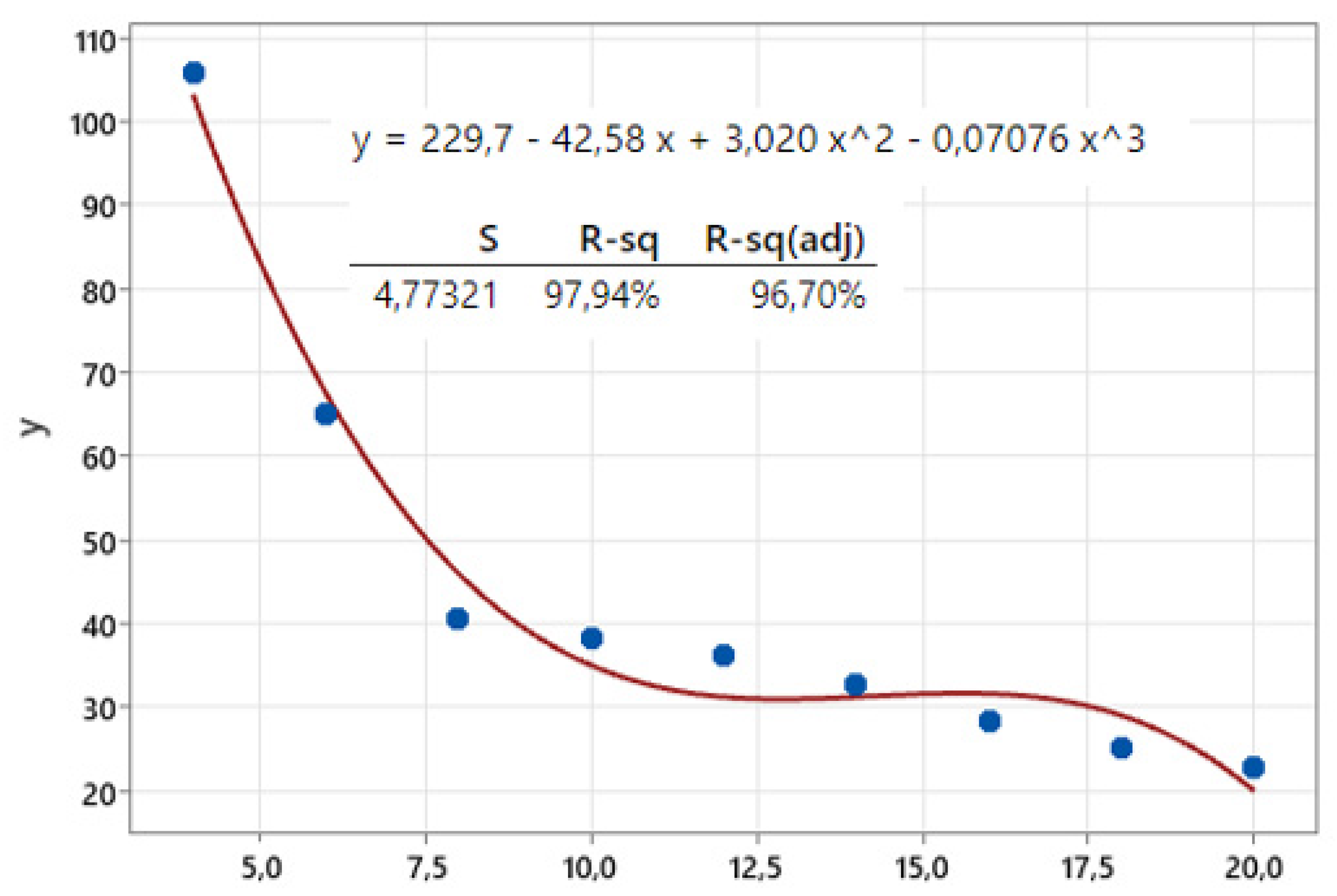
4.2. Structural Optimization

The container design and the load details of the silencer support structure are shown in Figure 11.
In the Results and Discussion section, it has been demonstrated that the finite element method (FEM) can be reliably applied in the design process, as supported by both literature comparisons and the acceptable error margins observed when compared with experimental methods. Consequently, FEM was also employed for structural analysis calculations in the optimization phase.
In optimization approaches, both an objective function and constraint functions are essential. While constraints naturally arise from the operating conditions, curve fitting techniques can be utilized to define objective functions effectively.
In this study, the total deformation and maximum shear stress of the M12-bolted muffler support plate—subjected to a constant shear force of 11,722 N (corresponding to a mass of 1200 kg)—were analyzed. The finite element analysis was conducted using 14,372 elements and 43,287 nodes, employing the sweep meshing method with a mesh size of 3 mm. The mesh quality ranged from a minimum of 0.077 to a maximum of 0.99. The Force-Fix support configuration is illustrated in Figure 12a, while the mesh element quality analysis is presented in Figure 12b.
The total deformation and maximum shear stress values are presented in Figure 13.
Based on the analysis results of the M12-bolted muffler bracket, a parametric analysis within the ANSYS structural analysis module was employed to determine the stress values for different bolt diameters. The parametric analysis performed for various bolt diameters is presented in Table 6.
Table 6 presents the parametric analysis results, illustrating the relationship between bolt diameter and shear stress under a constant 11,722 N load. The ANSYS structural analysis module was employed to evaluate the stress distribution across varying bolt diameters. The results indicate that shear stress decreases as bolt diameter increases, aligning with theoretical expectations.
Based on the stresses identified in the parametric analysis, a regression analysis was performed in Minitab, through which a function was derived using a curve-fitting approach. This function defines the objective function employed in this manuscript. The regression analysis graph is presented in Figure 14.
According to the regression analysis, the coefficient of determination (R2) approaches 1, with a calculated value of 0.9794. This indicates that under a constant load of 11,722 N, the derived equation predicts the stress per bolt—using bolt diameter as the independent variable—with an accuracy of 97.74%.
In this study, polynomial regression analysis was conducted using Minitab software, resulting in a third-degree polynomial equation to model the relationship between bolt diameter and stress. To prevent overfitting and ensure model reliability, direct regularization techniques such as L1 (Lasso) or L2 (Ridge) were not applied, as the experimental data naturally exhibits a well-balanced and smooth distribution. Instead, the model’s accuracy and suitability were evaluated using key statistical metrics. The coefficient of determination (R2) was found to be 0.9794, indicating a strong correlation between the model and the observed data. Additionally, the adjusted R2 was calculated as 96.70%, further reinforcing the model’s generalizability. The standard error (S) was measured at 4.77321, confirming that the model’s margin of error is within an acceptable range.
To assess the robustness of the regression model, cross-validation was performed. The third-degree polynomial equation was chosen as it provides an optimal balance between model complexity and predictive accuracy, effectively capturing the data trend without introducing excessive fluctuations for intermediate bolt diameters.
Additionally, a polynomial equation was derived using a curve-fitting method based on the data obtained from the parametric analysis. The resulting equation, which defines our objective function, is provided below.
y = S x = 0.07076 x 3 + 3.020 x 2 42.58 x + 229.7
In this problem, a safety factor of 2.5 is assumed between the normal strength and the yield strength of the bolt. The bolt cross-sectional area is denoted as Abolt, the bolt diameter as x, the yield strength as σy, and the normal stress as σ. The relevant equations are given below.
σ σ y
F A b o l t σ y 2.5 ,       F π x 2 4 σ y 2.5
In the assembly detail, the applied force F is 11,722 N, and the bolt quality is 8.8, resulting in a yield strength σy of 640 MPa. When these values are substituted, the constraint equation can be written as follows.
46,888 π x 2 256 0
The final form of the problem is given as follows. Lastly, the best model is identified and implemented using the optimal point.
max S x Subject   to   g 1 = 46,888 π x 2 256 0 x > 0 ,         S > 0
The defined optimization problem was solved using both the Lagrange Multiplier method and the Interior Point method for comparative purposes. The optimization results are presented in Figure 15.
According to the results, the optimal solution obtained using the Lagrange Multiplier method is 31.2439 MPa, while the Interior Point method yields a solution of 31.2314 MPa. As indicated in Table 6, both results correspond to the M14 bolted design. Therefore, it has been determined that the M14 bolted design should be implemented to ensure the load-bearing capacity of the silencer support under a load of 11,722 N.

5. Conclusions

This study addresses a gap in the literature by introducing two optimization models: one dedicated to noise reduction and the other to structural optimization. In addition to contributing to the field with these simultaneous optimization approaches, the research further enhances innovation through the development of a novel silencer design. Initially, a silencer model was designed and manufactured based on the exhaust noise levels of a sample generator, leading to the creation of the first optimization model. Subsequently, tensile testing and finite element analysis were performed on the connection elements used in the silencer assembly, culminating in the second optimization model.
Following a CFD analysis of a conventionally used silencer, flow analysis was conducted for the newly designed silencer, and the results were compared. The findings confirmed that the novel silencer and the pressure drop design were appropriate. This silencer was designed according to the specified noise levels of the Perkins 4008-30TAG3 engine, which has an electrical power of 1105 kW, ensuring a maximum noise level of 96 dB(A) at a distance of 1 m. The finalized silencer dimensions included a chamber diameter of Ø 800 mm, a length of 3000 mm, and an exhaust connection diameter of Ø 355.6 mm. Pressure drop measurements demonstrated that the diesel engine operated continuously without interruption. Noise level measurements were taken at a distance of 1 m from both the front and left side of the cabin while the generator was running recorded values of 85.1 dB(A) in front of the cabin and 74.4 dB(A) on the side, confirming compliance with the 96 dB(A) requirement. Based on these results, the first optimization model was developed to ensure optimal silencer performance. The primary goal was to create an optimized silencer model suitable for diesel generator sets and other industrial engines. An ideal design should maximize noise reduction while minimizing pressure loss. To achieve this balance efficiently, MATLAB’s fmincon optimization function was employed. Additionally, the code provided in the manuscript allows for the flexible addition or removal of constraint functions to ensure compliance with environmental emission standards.
For the structural experiments, ten identical test specimens were fabricated, each comprising two stacked ST 37 plates, 12 mm in thickness, fastened at the center with a zinc-coated M12 bolt. A tensile force was applied, and the corresponding data were recorded. In the finite element analysis, an average shear load of 39,054.04 N, consistent with the experimental findings, was applied to the same model. The analysis employed 26,972 finite elements and 14,400 nodes, utilizing the sweep meshing method with a mesh size of 3 mm. The mesh quality ranged between 0.13 and 0.99. The finite element analysis determined the maximum shear stress to be 271.99 MPa, while the experimental average shear stress was measured at 271.21 MPa. The ratio between these values was calculated as 1.003, which aligns with literature expectations. This validation confirms the reliability of the finite element analysis method for future structural calculations. Further computations involved designing a four-bolt-supported silencer support plate under real field conditions. The maximum shear stress problem was then reanalyzed using the ANSYS finite element software. With the plate size fixed, a parametric analysis was conducted for bolt diameters ranging from M4 to M20, and the results were documented. A curve-fitting method in Minitab was applied to these data, leading to the determination of an objective function, which was subsequently analyzed using regression analysis. The results indicated that the bolt diameter variable could predict shear stress with an accuracy of 97.94%. Following this, design constraints were defined, and a constraint function was formulated to establish the second optimization model.
To further validate the optimization, the same problem was solved using two different methods—the Lagrange Multiplier and Interior Point Method—for comparative analysis. The results indicated that the optimal solution obtained via the Lagrange Multiplier method was 31.2439 MPa, whereas the solution derived from the Interior Point method was 31.2314 MPa. Since both values correspond to an M14 bolted configuration in the silencer design plate, it was concluded that the M14 bolted design should be implemented to ensure the load-bearing capacity of the silencer support subjected to a load of 11.722 N.
Through these advancements, this study provides a comprehensive solution for engineers, researchers, and industry professionals by addressing both structural design and computational requirements while improving efficiency, performance, and practical implementation. Future studies will focus on a broader comparative analysis of silencer designs for diesel generator sets with varying power outputs. Additionally, alternative CFD software such as ANSYS Fluent will be employed for comparative analysis, and artificial neural network models will be integrated into future studies to predict noise reduction and pressure loss.

Funding

This research received no external funding.

Data Availability Statement

The original contributions presented in this study are included in the article. Further inquiries can be directed to the corresponding author.

Acknowledgments

In this study, the laboratories of Istanbul Health and Technology University and the production facilities of Özer Mekatronik A.Ş were utilized.

Conflicts of Interest

The author declare no conflicts of interest.

References

  1. Tanriver, K.; Dilibal, S.; Sahin, H. A novel design on polymeric material recycling technology. Acta Sci. Technol. 2021, 43, e56211. [Google Scholar] [CrossRef]
  2. Asaduzzaman, M.; Ali, M.H.; Pratik, N.A.; Lubaba, N. Exhaust heat harvesting of automotive engine using thermoelectric generation technology. Energy Convers. Manag. X 2023, 19, 100398. [Google Scholar] [CrossRef]
  3. Bönnen, D.; Bamdad-Soufi, D.; Steinkilberg, H.; Abram, K. Possibilities and Constraints for Lightweight in Exhaust Systems. In Proceedings of the 8th International Styrian Noise, Vibration, Harshness Congress (ISNVH), Graz, Austria, 2–4 July 2014; pp. 81–97. [Google Scholar]
  4. Huang, L.; Simon, T.; Zhang, M.; Yeom, T.; North, M.; Cui, T.H. Noise Measurements and Reduction for High-Frequency Vibrating Devices in the Application of Cooling Electronics. In Proceedings of the ASME International Mechanical Engineering Congress and Exposition, Houston, TX, USA, 9–15 November 2012; pp. 1497–1504. [Google Scholar]
  5. Kang, I.S.; Yang, S.M. Effect of Confluence Geometry of Dual Exhaust System on Quietness and Power. Int. J. Automot. Technol. 2021, 22, 27–36. [Google Scholar] [CrossRef]
  6. Lin, T.-H.; Deng, J.; Chen, Y.-C. Using Response Surface for Searching the Nearly Optimal Parameters Combination of the Foam Concrete Muffler. Materials 2022, 15, 8128. [Google Scholar] [CrossRef]
  7. Kadyrov, A.; Bembenek, M.; Sarsembekov, B.; Kukesheva, A.; Nurkusheva, S. The Influence of the Frequency of Ultrasound on the Exhaust Gas Purification Process in a Diesel Car Muffler. Appl. Sci. 2024, 14, 5027. [Google Scholar] [CrossRef]
  8. Nursal, R.S.; Hashim, A.H.; Nordin, N.I.; Abdul Hamid, M.A.; Danuri, M.R. CFD analysis on the effects of exhaust backpressure generated by four-stroke marine diesel generator after modification of silencer and exhaust flow design. ARPN J. Eng. Appl. Sci. 2017, 12, 1271–1280. [Google Scholar]
  9. Gupta, A.; Mishra, P.C. Optimization of emission characteristics of spark ignition engine with chambered straight muffler running in methanol blend: An engine development technique for environmental sustainability. J. Clean. Prod. 2019, 238, 117778. [Google Scholar] [CrossRef]
  10. Sunny Manohar, D.; Krishnaraj, J. Modeling and analysis of Exhaust Manifold using CFD. IOP Conf. Ser. Mater. Sci. Eng. 2018, 455, 012132. [Google Scholar] [CrossRef]
  11. Altun, A.; Adin, M.; İlçin, K. Monohydric aliphatic alcohols as liquid fuels for using in internal combustion engines: A review. Proc. Inst. Mech. Eng. Part E J. Process. Mech. Eng. 2023, 238, 1941–1975. [Google Scholar] [CrossRef]
  12. Uyar, M.; Aydın, H. Production of low sulfur diesel-like fuel from crude oil wastes by pyrolytic distillation and its usage in a diesel engine. Energy 2022, 244, 122683. [Google Scholar] [CrossRef]
  13. Yadav, G.P.K.; Dwivedi, Y.D.; Kumar, M.L.; Sonia, P.; Bandhu, D.; Nagendra, J.; Abass, M.A. CFD simulation analysis of a rectangular chambered muffler model for a C.I. engine. Int. J. Interact. Des. Manuf. 2024, 18, 3183–3192. [Google Scholar] [CrossRef]
  14. Peng, Q.; Liu, R.; Zhou, G.; Zhao, X.; Dong, S.; Zhang, Z.; Zhang, H. Summary of Turbocharging as a Waste Heat Recovery System for a Variable Altitude Internal Combustion Engine. ACS Omega 2023, 8, 27932–27952. [Google Scholar] [CrossRef]
  15. Li, S.; Zang, Z.; Zhang, S.; Zhao, X. Low-frequency duct noise control using coupled loudspeakers. J. Acoust. Soc. Am. 2023, 153, 1163–1178. [Google Scholar] [CrossRef]
  16. Archana, S.K.; Surve, F. Transmission loss and end-correction modeling of extended inlet-outlet expansion chamber muffler and the concentric tube resonator. J. Acoust. Soc. Am. 2022, 151, A55. [Google Scholar]
  17. Dogra, S.; Gulia, P.; Gupta, A. Noise isolation in building HVAC system using recyclable plastic bottles. Proc. Inst. Mech. Eng. Part C J. Mech. Eng. Sci. 2023, 238, 3327–3337. [Google Scholar] [CrossRef]
  18. Rahmani, N.; Khastavan, Y.; Variani, A.S.; Ahmadi, S. Compressor pulsation noise attenuation using reactive silencer with various configurations: A theoretical and experimental study. Heliyon 2024, 10, e27263. [Google Scholar] [CrossRef]
  19. Villau, M.; Rämmal, H.; Lavrentjev, J. Acoustic analysis of compact silencer solution based on microperforated panel. AIP Conf. Proc. 2024, 2989, 030014. [Google Scholar]
  20. Fu, J.; Gu, S.; Wu, L.; Wang, N.; Lin, L.; Chen, Z. Research on Optimization of Diesel Engine Speed Control Based on UKF-Filtered Data and PSO Fuzzy PID Control. Processes 2025, 13, 777. [Google Scholar] [CrossRef]
  21. Kang, I.-S.; Yang, S.-M. The Effect of Back Pressure Change on Exhaust Emissions According to the Confluence Geometry of a Dual Exhaust System in Idling. Appl. Sci. 2022, 12, 1855. [Google Scholar] [CrossRef]
  22. Li, F.; Yuan, W.; Ma, Y.; Fu, J. Structural Performance Analysis and Optimization of Small Diesel Engine Exhaust Muffler. Processes 2024, 12, 2186. [Google Scholar] [CrossRef]
  23. Li, K.; Xiao, B.; Wang, Y.; Jia, J.; Wu, X. Applications of Electric Heating Technology in Vehicle Exhaust Pollution Control. Processes 2024, 12, 298. [Google Scholar] [CrossRef]
  24. Wansom, A.; Maneechot, P.; Jiteurtragool, N.; Vitidsant, T. PM2.5 Collection Enhancement in a Smart Hybrid Wet Scrubber Tower. Processes 2023, 11, 3306. [Google Scholar] [CrossRef]
  25. Mikky, Y.A.; Bhran, A.A.; El-Araby, R.Y.; Mohamed, A.M.A.; Gadallah, A.G.; Shoaib, A.M. Optimization of Biodiesel–Nanoparticle Blends for Enhanced Diesel Engine Performance and Emission Reduction. Processes 2024, 12, 2471. [Google Scholar] [CrossRef]
  26. Ma, Q.; Luo, C.; Wan, X.; Xu, Z. Numerical Investigation into Acoustics Characteristics towards Pressure Reducing Valve with High Ratio of Reduced Pressure. Processes 2024, 12, 2110. [Google Scholar] [CrossRef]
  27. Zhang, S.-W.; Wang, F.; Li, C.; Zhu, S.-M.; Lan, H.-Q. Study on Acoustic–Vibration Characteristics and Noise Reduction Methods for Elbows. Processes 2025, 13, 389. [Google Scholar] [CrossRef]
  28. Alexanda Petrovic, B.; Masoudi Soltani, S. Optimization of Post Combustion CO2 Capture from a Combined-Cycle Gas Turbine Power Plant via Taguchi Design of Experiment. Processes 2019, 7, 364. [Google Scholar] [CrossRef]
  29. Tanriver, K.; Ay, M. Modifying the Refuse Chute Design to Prevent Infection Spread: Engineering Analysis and Optimization. Appl. Sci. 2024, 14, 9638. [Google Scholar] [CrossRef]
  30. Binh Pham, V.; Hung Pham, C.; Gregory, J.H. Block shear and tear-out in bolted connections as limited by curling. Thin-Walled Struct. 2023, 187, 110754. [Google Scholar] [CrossRef]
  31. Li, Y.; Long, T.; Luo, Z.; Wen, C.; Zhu, Z.; Jin, L.; Li, B. Numerical and experimental investigations on dynamic behaviors of a bolted joint rotor system with pedestal looseness. J. Sound Vib. 2024, 571, 118036. [Google Scholar] [CrossRef]
  32. Cheng, L.; Huan, H.; Ke, Y. Elastic-plastic analysis, and riveting energy control for dual-robot pneumatic riveting system. Proc. Inst. Mech. Eng. Part C J. Mech. Eng. Sci. 2020, 234, 1836–1847. [Google Scholar] [CrossRef]
  33. Tanriver, K.; Ay, M. Investigation of flue gas temperature effects in natural gas fueled Systems: Experimental thermal performance and structural optimization. Int. J. Heat Fluid Flow 2024, 107, 109428. [Google Scholar] [CrossRef]
  34. Kong, F.; Zhen, X.; Yuqi, Y.; Wang, Z. Analysis of Fracture Damage Mechanical Properties of Particle Reinforced Polymer Composite Film Based on Micro-macro–Finite Element Method. Model. Simul. Mater. Sci. Eng. 2024, 32, 065010. [Google Scholar] [CrossRef]
  35. Yi, W.; Zhu, L.; Wang, M. Sun Experimental and numerical study on mechanical performance of single shear bolted connections with novel elliptical one-sided bolts. Structures 2024, 62, 106223. [Google Scholar] [CrossRef]
  36. He, M.; Zhang, Q.; Sun, X.; Alhaddad, W. An experimental and numerical study on the shear performance of friction-type high-strength bolted connections used for CLT-steel hybrid shear walls. Eng. Struct. 2024, 306, 117868. [Google Scholar] [CrossRef]
  37. Gao, X.; Wang, W. Bolt load looseness measurement for slip-critical blind bolt by ultrasonic technique: A feasibility study with calibration and experimental verification. Struct. Health Monit. 2024, 23, 527–538. [Google Scholar] [CrossRef]
  38. Ye, J.; Quan, G.; Yun, X.; Guo, X.; Chen, J. An improved and robust finite element model for simulation of thin-walled. Eng. Struct. 2022, 250, 113368. [Google Scholar] [CrossRef]
  39. ISO 14163:1998; Acoustics—Guidelines for Noise Control by Silencers. ISO: Geneva, Switzerland, 1998.
  40. Kovachev, N.Y.; Mihova, V.A.; Georgiev, I.R.; Pavlov, V.T. Assessing the Impact of Speed and Type of Road Surface on the Noise Level in a Passenger Car Cabin. J. Phys. Conf. Ser. 2023, 2675, 012014. [Google Scholar] [CrossRef]
  41. EN 1090-1:2009+A1:2011; Execution of Steel Structures and Aluminium Structures—Part 1: Requirements for Conformity Assessment of Structural Components. BSI: London, UK, 2011.
  42. ISO 3834-2:2021; Quality Requirements for Fusion Welding of Metallic Materials—Part 2: Comprehensive Quality Requirements. ISO: Geneva, Switzerland, 2021.
  43. ISO 6892-1:2016; Metallic Materials—Tensile Testing—Part 1: Method of Test at Room Temperature. ISO: Geneva, Switzerland, 2016.
  44. İncesu, A.; Ercan, B.; Çevik, E.; Akgül, Y. Reference material development process for tensile test method. Pamukkale Univ. J. Eng. Sci. 2022, 28, 58–62. [Google Scholar] [CrossRef]
  45. Tanriver, K.; Ay, M. Experimental and numerical analysis of bolted two plates using a developed shear theory. J. Theor. Appl. Mech. 2023, 61, 509–520. [Google Scholar] [CrossRef]
  46. Uysal, M.; Bakar, O.; Doğan, Y. Comparison of Noise Analysis with Finite Elements Method and Test Values in Diesel Generator Sets. DEU FMD 2022, 24, 463–474. [Google Scholar] [CrossRef]
  47. Perkins Engine Datasheet—4008-30TAG3 Diesel Engine—Electropak. Available online: https://www.gucbirjenerator.com/engine/perkins/4008-30TAG3.pdf (accessed on 4 March 2025).
  48. Nohutcu, O. CFD Simulation of Airflow in a New Receiver Concept for High-Temperature Solar Heating. Master’s Thesis, FH Aachen University of Applied Sciences, Aachen, Germany, 2023. [Google Scholar]
  49. Kubenova, M.; Kuterbekov, K.; Bekmyrza, K.; Kabyshev, A.; Kabdrakhimova, G.; Atamurotov, F.; Ibrahim, W. Exhaust waste heat recovery system using thermoelectric generator: A prospective of novel simulation technique toward low-carbon technology. Int. J. Low-Carbon Technol. 2025, 20, 8–24. [Google Scholar] [CrossRef]
  50. NEC Najah Engineering Consultants LLC-NEC Acostix-ExTuner Program Sheets. Available online: https://najahengineering.com/acostix.html (accessed on 4 March 2025).
  51. EN 13384-1:2015; Chimneys—Thermal and Fluid Dynamic Calculation Methods—Part 1: Chimneys Serving One Heating Appliance. BSI: London, UK, 2015.
  52. Tzouka, E.; Karavasilis, T.; Kashani, M.M.; Afshan, S. Finite element modelling of push-out tests for novel locking nut shear connectors. Structures 2021, 33, 1020–1032. [Google Scholar] [CrossRef]
  53. Navarro, M.; Ivorra, S.; Varona, F.B. Parametric finite element analysis of punching shear behaviour of RC slabs reinforced with bolts. Comput. Struct. 2020, 228, 106147. [Google Scholar] [CrossRef]
  54. Hosseini, S.M.; Mashiri, F.; Mirza, O. Parametric study of innovative bolted shear connectors using 3D finite element modelling. J. Constr. Steel Res. 2021, 179, 106565. [Google Scholar] [CrossRef]
  55. Tanriver, K.; Ay, M. Topology Optimization of a Steel Construction Bolt Under Boundary Conditions. Euroasia J. Math. Eng. Nat. Med. Sci. 2020, 7, 31–47. [Google Scholar]
  56. Tanriver, K.; Ay, M. Experimental, Software and Topological Optimization Study of Unpredictable Forces in Bolted Connections. Tech. Gaz. 2023, 30, 1175–1184. [Google Scholar]
  57. Tanriver, K.; Ay, M. Efficient Path Planning for Drilling Processes: A Hybrid Approach of Genetic Algorithm and Ant Colony Optimization. Trans. Famena 2024, 48, 125–140. [Google Scholar] [CrossRef]
  58. Tanriver, K.; Ay, M. Simulation of Speed Reducer Design with the Modified Ant Colony Optimization Algorithm. J. Eng. Sci. Res. 2024, 6, 53–64. [Google Scholar]
  59. Andersen, P.R.; Henríquez, V.C.; Aage, N. On the validity of numerical models for Visco thermal losses in structural optimization for micro-acoustics. J. Sound Vib. 2023, 547, 117455. [Google Scholar] [CrossRef]
  60. Cool, V.; Sigmund, O.; Aage, N.; Naets, F.; Deckers, E. Vibroacoustic topology optimization for sound transmission minimization through sandwich structures. J. Sound Vib. 2024, 568, 117959. [Google Scholar] [CrossRef]
  61. Fischer, S.; Szürke, S.K. Detection Process of Energy Loss in Electric Railway Vehicles. Facta Univ. Ser. Mech. Eng. 2023, 21, 81–99. [Google Scholar] [CrossRef]
  62. Li, W.; Wang, Z.; Brennan, M.J.; Yang, T. Design and optimization of a two-degrees-of-freedom single-sided vibro-impact nonlinear energy sink for transient vibration suppression of a thin plate. J. Sound Vib. 2024, 587, 118512. [Google Scholar] [CrossRef]
  63. Maury, C.; Bravo, T.; Amielh, M.; Mazzoni, D. Acoustic Pressure Amplification through In-Duct Sonic Black Holes. Appl. Sci. 2024, 14, 4699. [Google Scholar] [CrossRef]
Figure 1. Noise and frequency graph [14].
Processes 13 00887 g001
Figure 2. Silencer model.
Processes 13 00887 g002
Figure 3. Silencer supports: (a) model and (b) tensile test [38].
Processes 13 00887 g003
Figure 4. Noise and frequency graph [44].
Processes 13 00887 g004
Figure 5. Silencer design parameters.
Processes 13 00887 g005
Figure 6. Silencer design preliminary calculation result [50].
Processes 13 00887 g006
Figure 7. Silencer manufacturing stages.
Processes 13 00887 g007
Figure 8. Conventional silencer flow simulation: (a) velocity and (b) pressure drop.
Processes 13 00887 g008
Figure 9. The novel designed silencer flow simulation: (a) convergence plot and (b) pressure drop (p1).
Processes 13 00887 g009
Figure 10. MATLAB performance-based optimization result screen.
Processes 13 00887 g010
Figure 11. Container and silencer installation design.
Processes 13 00887 g011
Figure 12. Finite element analysis: (a) fixed support load selection and (b) mesh element quality.
Processes 13 00887 g012
Figure 13. Finite element analysis: (a) total deformation and (b) maximum shear stress.
Processes 13 00887 g013
Figure 14. Regression analysis graph with Minitab.
Processes 13 00887 g014
Figure 15. MATLAB result screen: (a) Lagrange method and (b) Interior Point method.
Processes 13 00887 g015
Table 1. Silencer specification.
Part NoDiameterThickMaterial SpecificationWelding Process
(mm)(mm)
Silencer bodyØ 8003.0ST 37Manuel 135 MAG
Sound absorber isolationØ 796100.0Rockwool 100 kg/m3-
Isolation CoverØ 5963.0ST 37 perforated sheetManuel 135 MAG
Inlet PipeØ 355.63.0ST 37Manuel 135 MAG
Outlet PipeØ 355.63.0ST 37Manuel 135 MAG
Table 2. Diesel engine data [47].
DescriptionUnitsType of Operation and Application 50 Hz @1500 rev/min
Base LoadPrime PowerStandby PowerData Used
Exhaust Gas Flowm3/min180203240240
Exhaust Gas Temp.°C460473482482
Allowable Back PressureKPa77
Table 3. The silencers performance comparison.
Performance CriteriaConventional SilencerThe Novel Designed Silencer
Preliminary Calculation (Design, Pressure Loss, Noise Level)-The same calculations previously performed are used for the entire design+A preliminary calculation is performed before each design
Noise Level ≤ 96 dB(A) at 1 m.110It does not meet the design requirements88.1It meets the design requirements
Pressure Loss ≤ 7 KPa dB(A)0.160It meets the design requirements, but it is too tolerant from an engineering perspective6.149It meets the design requirements
Dimension ≤ Container Dimensions+Outer dimensions remain the same+Outer dimensions remain the same
Structural Optimization -None+An optimization model has been proposed to be calculated for the users
Table 4. Tensile test result.
Bold DiameterPlate DimensionsSample NameTensile Stress (MPa)Load (N)
M12 × 5012 × 100 × 120Bold Sample 1273.0039,312.45
M12 × 5012 × 100 × 120Bold Sample 2267.4938,518.27
M12 × 5012 × 100 × 120Bold Sample 3269.0638,744.56
M12 × 5012 × 100 × 120Bold Sample 4282.3040,651.37
M12 × 5012 × 100 × 120Bold Sample 5265.8138,276.59
M12 × 5012 × 100 × 120Bold Sample 6272.5339,243.84
M12 × 5012 × 100 × 120Bold Sample 7275.0639,609.19
M12 × 5012 × 100 × 120Bold Sample 8267.9938,590.41
M12 × 5012 × 100 × 120Bold Sample 9267.2838,488.92
M12 × 5012 × 100 × 120Bold Sample 10271.5639,104.78
Table 5. Total error.
ParameterExperimental ResultSimulation ResultTotal Error (%)
Front Noise Reduction (dB(A))85.588.1−3.04%
Side Noise Reduction (dB(A))74.488.1−18.41%
Pressure Loss (KPa)6.006.15−2.48%
Structural Stress (MPa)271.21271.99−0.29%
Table 6. Parametric analysis for bold diameter and shear stress.
Load (N)Bolt Diameter (mm)Stress Analysis Result (MPa)
11,7224105.77
665.11
840.62
1038.45
1237.03
1432.89
1628.42
1825.41
2022.98
Disclaimer/Publisher’s Note: The statements, opinions and data contained in all publications are solely those of the individual author(s) and contributor(s) and not of MDPI and/or the editor(s). MDPI and/or the editor(s) disclaim responsibility for any injury to people or property resulting from any ideas, methods, instructions or products referred to in the content.

