Article

Control Mechanism of Earthquake Disasters Induced by Hard–Thick Roofs’ Breakage via Ground Hydraulic Fracturing Technology

1
State Key Laboratory of Coal Mine Disaster Dynamics and Control, Chongqing University, Chongqing 400044, China
2
School of Resources and Safety Engineering, Chongqing University, Chongqing 400044, China
*
Author to whom correspondence should be addressed.
Processes 2025, 13(3), 919; https://doi.org/10.3390/pr13030919
Submission received: 11 February 2025 / Revised: 1 March 2025 / Accepted: 4 March 2025 / Published: 20 March 2025

Abstract

:
To investigate the mechanism of ground hydraulic fracturing technology in preventing mine earthquakes induced by hard–thick roof (HTR) breakage in coal mines, this study established a Timoshenko beam model on a Winkler foundation incorporating the elastoplasticity and strain-softening behavior of coal–rock masses. The following conclusions were drawn: (1) The periodic breaking step distance of a 15.8 m thick HTR on the 61,304 Workface of Tangjiahui coal mine was calculated as 23 m, with an impact load of 15,308 kN on the hydraulic support, differing from measured data by 4.5% and 4.8%, respectively. (2) During periodic breakage, both the bending moment and elastic deformation energy density of the HTR exhibit a unimodal distribution, peaking 1.0–6.5 m ahead of cantilever endpoint O, while their zero points are 40–41 m ahead, defining the breaking position and advanced influence area. (3) The PBSD has a cubic relationship with the peak values of bending moment and elastic deformation energy density, and the exponential relationship with the impact load on the hydraulic support is F Z J = 5185.2 e 0.00431 L p . (4) Theoretical and measured comparisons indicate that reducing PBSD is an effective way to control impact load. The hard–thick roof ground hydraulic fracturing technology (HTRGFT) weakens HTR strength, shortens PBSD, effectively controls impact load, and helps prevent mine earthquakes.

1. Introduction

The concept of a “hard roof” refers to rock strata characterized by high strength and structural integrity, commonly found in rock types like sandstone and shale [1]. In China, around half of the mining areas grapple with the challenges posed by such hard roofs [2,3]. The frequent occurrence of coal mine disasters is caused by the fracture of hard–thick roofs. In mining regions such as Shanxi, Shaanxi, and Inner Mongolia in China, there is a high frequency of impacts and extreme mine earthquake disasters, making safe coal mining difficult to ensure. From a theoretical standpoint, particularly in beam theory, hard roofs with a span-to-thickness ratio of less than 10, fitting the criteria of the Timoshenko beam theory, are classified as hard–thick roofs (HTRs) [4]. These HTRs significantly contribute to mine earthquakes, ultimately resulting in dynamic disasters in mining activities, such as gas outbursts [5] and impact ground pressure [6,7], which pose severe threats to the safe extraction of coal. Their high strength, considerable thickness, and underdeveloped fractures enable them to form extensive suspended roof areas—up to 100,000 m2—thereby creating an environment conducive to the genesis of high-energy mine earthquakes [8]. As mining areas expand, the HTRs’ periodic breakage can trigger high-energy mine earthquakes [6,9], leading to dynamic disasters at a workface and posing substantial risks to the safety of coal mine workers [10,11,12]. Tragic incidents underscore the severity of these risks, such as the “10.29” rockburst accident at Longyao Coal Mine in 2018, which resulted in 21 fatalities, and the “10.11” accident at Hujiagou Coal Mine in 2021, which resulted in 4 deaths, 6 severe injuries, and 20 minor injuries [13,14].
To mitigate the mine earthquake disasters engendered by HTRs, experts have devised various prevention and control strategies, including underground hydraulic fracturing, blasting, and gangue filling—all of which have demonstrated effectiveness in managing such challenges [15]. In recent years, to extend the control of mine earthquake disasters across larger areas at a workface without impacting production processes, the hard–thick roof ground hydraulic fracturing technology (HTRGFT) was proposed [16]. This innovative approach entails generating a multitude of artificial fractures in HTRs, thus diminishing their strength and reducing the periodic breaking step distance (PBSD). In 2009, the HTRGFT was first applied to manage the issues induced by HTRs at Tongxin Coal Mine, part of the Datong Coal Mine Group in China [17]. Following its initial success, this technology was further adopted and implemented in other mines, including Tashan and Madaotou mines, and all these on-site practices show that HTRGFT can effectively control and curtail the dynamic disaster [18]. Post 2019, this method extended its reach, being applied in coal mines across Inner Mongolia, Shaanxi, and Gansu provinces in China [19].
Since the introduction of the HTRGFT in controlling mine earthquake disasters induced by HTRs, researchers have explored various mechanical models to understand its mechanism in mitigating dynamic disasters. These models include plane strain models, elastic foundation beam models, and masonry beam models. For instance, the cantilever beam model was utilized to examine the correlation between the cantilever beam length and the stress concentration coefficient ahead of a workface [20]. In the hydraulic fracturing of HTRs, the model reveals that one end of the working face is fixedly supported, but it does not consider the softening of the coal seam. That study indicated that the HTRGFT effectively shortens the cantilever beam length, consequently reducing the stress concentration. Building upon these insights, further research, based on the semi-infinite plane strain model, assessed the stress distribution of the mining area by the HTRGFT and drew the conclusion that the HTRGFT creates a pressure relief protective layer, a pressure relief zone, in HTRs. When these HTRs undergo periodic breakage, the resulting dynamic disaster at the workface is often evidenced by hydraulic supports bearing an impact load beyond their rated resistance. Expanding on this notion, a model based on the masonry beam theory was developed, which is that the broken rocks are supported by hydraulic supports and coal wall [17]. That study examined the relationship between PBSD and hydraulic support resistance, concluding that the HTRGFT shortens PBSD, effectively managing impact ground pressure at the workface. However, their approach did not account for the impact load generated by the release of elastic deformation energy during periodic breakage. To fill this gap, some scholars [21,22] computed this impact load. For example, the Euler beam was used on the Winkler Foundation model to establish an energy concentration model for HTRs [21]. In this model evaluation system, the subsidence and fracture of HTRs were considered the main causes of dynamic disasters at the working face. The study suggests that filling mining with a filling rate of 70% can prevent dynamic disasters. However, for a rock layer thickness of 30 m, the model does not take into account the lateral shear deformation of the rock strata. This model analyzed energy accumulation, transformation, and release during periodic breakage but overlooked impact load calculations and lateral shear deformation of HTRs. Further contributing to this body of research, some scholars conducted surveys across 23 mines in typical mining regions of China. They observed that the breaking size of hard roofs at most workfaces aligns with the Timoshenko beam theory [19]. This observation led some scholars to adopt the Timoshenko beam and Euler beam in constructing mechanical models for the cantilever and clamped sections, respectively. In terms of Euler beam theory, the application of HTR disaster prevention in coal mines has been studied in the context of thick coal seam disaster control. This model has been used to mitigate roof energy release, reducing the risk of rockburst by 20% [23]. These models also explored the processes of energy accumulation, transformation, release, and the ensuing impact load on hydraulic supports at a workface. However, this methodology, particularly the simplification of the clamped section to the Euler beam, has sparked debate. Moreover, it tends to overlook the plastic characteristics and strain-softening behavior of the coal–rock mass that supports the HTRs, highlighting the need for more comprehensive modeling approaches in understanding and mitigating dynamic disasters in mining activities.
Therefore, this study develops a novel approach incorporating elastoplastic and strain-softening behaviors of the coal-rock mass. A new stiffness calculation formula is proposed, and a Timoshenko beam model on a Winkler foundation is established to analyze energy concentration and dispersion during HTR periodic breakage. This approach enables the precise calculation of mine earthquake energy and impact load on hydraulic supports, ultimately guiding application of the HTRGFT for mine earthquake control at Tashan Coal Mine.

2. HTRGFT for Mine Earthquake Disasters in Workfaces

For mine earthquake disasters in workfaces induced by HTRs’ periodic breakage, this section mainly introduces mine earthquake disasters and the HTRGFT. Then, the weakening mechanism of the HTRGFT is analyzed. The evaluation of HTRGFT control effect is discussed in both of the following sections.

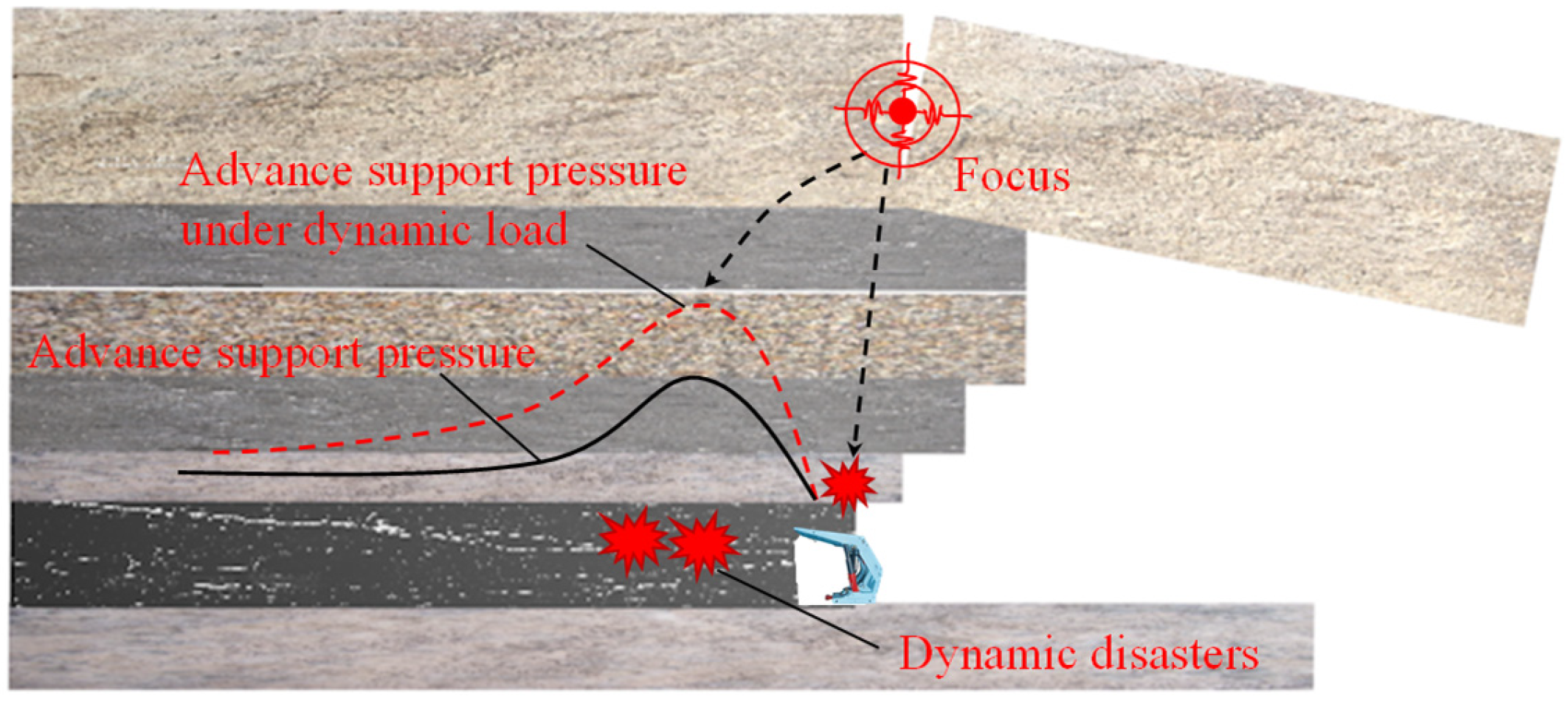
2.1. Mechanism of Mine Earthquake Disaster Occurrence in Workfaces Due to HTRs’ Periodic Breakage

During the coal mining process, these HTRs tend to form large suspended areas [24]. Prior to their periodic breakage, HTRs undergo bending and shearing deformations, continuously accumulating bending deformation energy and shear strain energy. This process simultaneously causes an instantaneous increase in the supporting pressure ahead of the workface. When the cantilever beam length reaches its limit, these HTRs fracture rapidly, releasing a substantial amount of energy. This energy release induces intense vibrations in the coal–rock mass, triggering dynamic disasters such as instant floor heave, extensive coal rib spalling, and hydraulic support damage, which pose serious threats to personnel safety, as illustrated in Figure 1. In China, typical instances of such dynamic disasters, induced by the sudden breakage of HTRs over large suspended areas due to mining activities, include the “2.18” rockburst disaster at Fangshan Coal Mine, the “1.3” rockburst disaster at Dongtan Coal Mine, and the “7.22” rockburst disaster at Dongbaowei Coal Mine [25,26]. These incidents exemplify the potential hazards associated with the HTRs’ periodic breakage.
Based on the Energy Theory proposed by Cook [14], rockburst disasters happen in the following conditions:
Δ U > Δ E
In the formula, Δ U represents the energy released by the breakage and destabilization process of the HTRs, while Δ E denotes the energy consumed during the transfer process.
In practical engineering scenarios, the spatial position of HTRs is fixed, and the energy transfer path remains constant, which implies that the consumed energy is also fixed. Mine earthquake disasters at the workface occur when the energy released by the HTRs’ periodic breakage exceeds the energy consumed in the transfer process. Therefore, the magnitude of energy released by the HTRs’ periodic breakage is a key factor in assessing the occurrence of such dynamic disasters, and the quantitative mechanical relationship between them is established in Section 3.

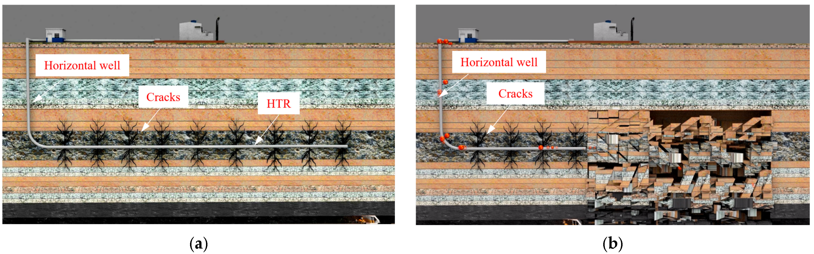
2.2. HTR Ground Fracturing Technology (HTRGFT)

In practical engineering, altering the thickness and load of HTRs in coal mines is often difficult. However, their strength can be modified using techniques like hydraulic fracturing or blasting, which influence the PBSD. Recent advancements in HTR ground fracturing technology (HTRGFT) have demonstrated significant success in shortening this step distance, thereby mitigating impact-related disasters at workfaces [17]. As depicted in Figure 2a, fracturing wells are strategically located at the center of the workface along its advancing direction. Artificial fractures are created using a combined approach of “composite directional perforation + bridge plug”, enabling effective fracturing of the HTRs. Horizontal fractures, extending over 100 m, cover the entire workface, while vertical fractures penetrate the full height of the HTR. Figure 2b illustrates how the resulting cracks weaken the rock mass strength, reduce the PBSD, and effectively control the occurrence of severe mining pressure.

2.3. Strata Weakening Mechanism of the HTRGFT

The HTRGFT is a sophisticated procedure that involves injecting acid fluid into rock layers to create artificial fractures, effectively weakening the rock mass. This weakening occurs primarily through two mechanisms: corrosion of the rock layer and destruction of its integrity, resulting in a significant reduction in the overall rock strength [4,27].
As for the first mechanism, to illustrate, the HTR overlying the 8204 Workface in Tashan Coal Mine in China, composed of medium-grained sandstone, was subjected to X-ray diffraction (XRD) tests before and after acidification. The XRD diffraction patterns, as depicted in Figure 3a, demonstrate the disappearance of the characteristic peaks of carbonate minerals following acidification, indicating that the acid fracturing fluid primarily reacts with carbonate minerals present in the medium-grained sandstone [28]. This reaction leads to the formation of numerous acid-etched pores, substantially increasing the porosity within the rock. As the acidification process progresses, there is a corresponding decrease in both the uniaxial compressive strength and tensile strength of the medium-grained sandstone, which also exhibits a layered structure within the sandstone.
As for the second mechanism, the HTRs’ integrity was destructed by diminishing the strength of the rock layer through extensive artificial fractures. These fractures, as shown in Figure 3b, create a multitude of structural weak planes within the rock layer. When the HTR undergoes periodic breakage, it is more susceptible to tensile failure along these weak planes, thus effectively lowering the roof’s overall strength and contributing to the efficacy of the ground fracturing technique in controlling mine earthquake disasters in coal mines [29,30].

3. Model of the Influent of Mine Earthquake on Impact Load During HTRs’ Periodic Breakage

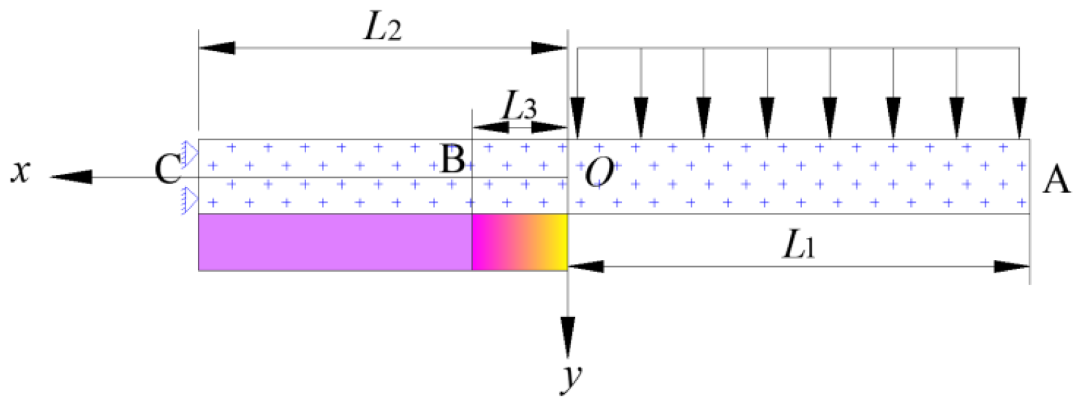
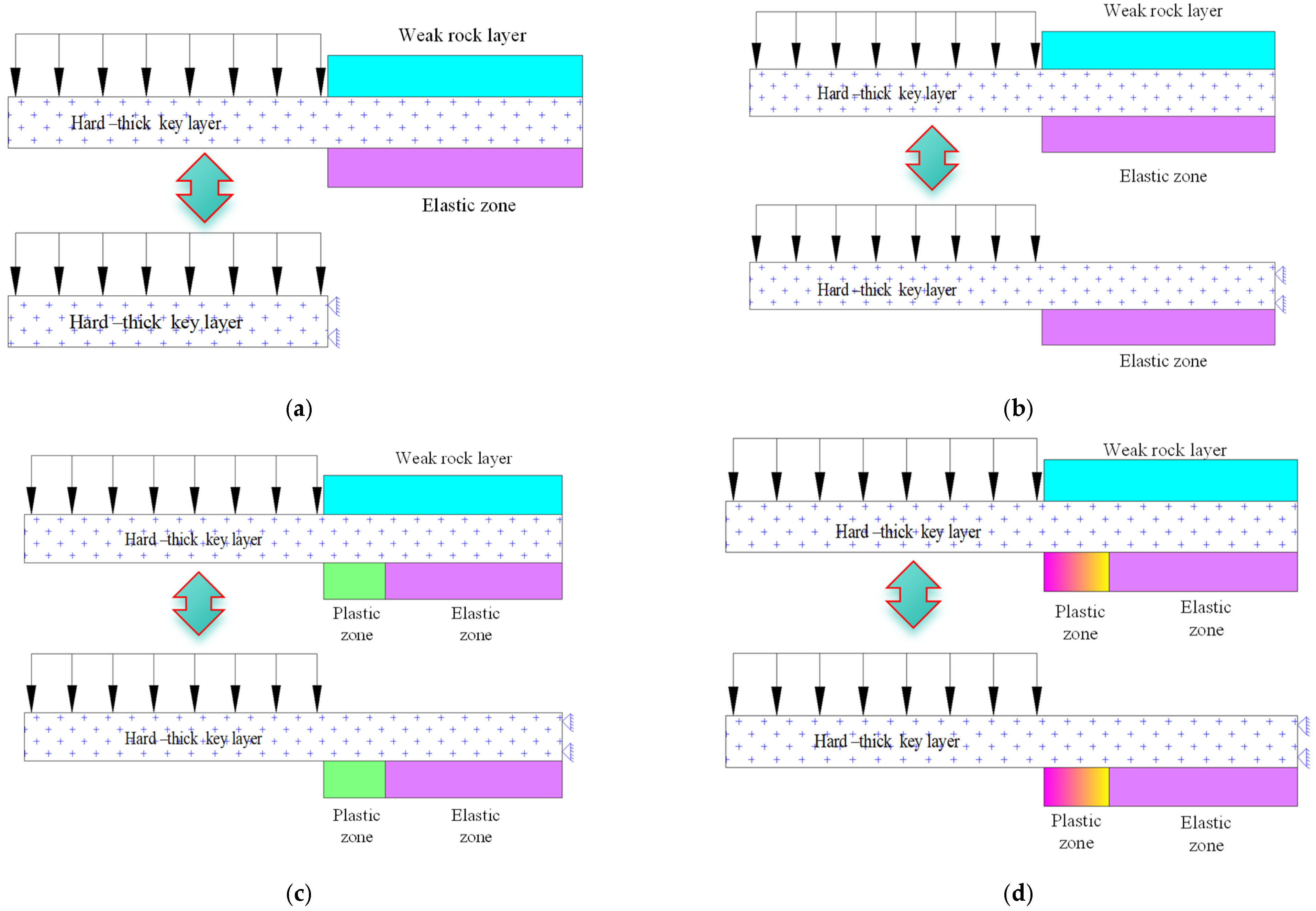
3.1. Periodic Breaking Mechanical Model of HTRs

During HTRs’ periodic breakage, one end is clamped between the upper and lower rock layers, while the other remains free. The cantilevered section bears gravitational forces from overlying rock layers, and the coal–rock mass beneath undergoes plastic deformation. A Timoshenko beam model, as illustrated in Figure 4, is used to represent the boundary, force state, and material characteristics of the HTRs. The coordinate origin, O, is at the cantilever boundary, with the x-axis along the HTR’s central axis (pointing left) and the y-axis pointing downward. For sufficiently large x = −L2, the beam boundary is assumed as fixed. The underlying rock layers are divided into elastic and plastic sections: the plastic section spans from x = 0 to −L3, and the elastic section from x = −L3 to −L2, accounting for plasticity and strain-softening behavior.

3.2. Timoshenko Beam Theory on Winkler Foundation

The Euler beam theory assumes that a cross-section perpendicular to the beam’s central axis remains flat and perpendicular after deformation, simplifying the control equation to a single variable, the deflection w. This approach is valid only when the thickness-to-span ratio is between 1/5 and 1/10 [31]. However, for HTRs, this ratio often exceeds the threshold, making Euler beam theory insufficient [32]. To account for shear deformation [33,34], Timoshenko beam theory introduces an additional variable—the section’s rotation angle—and discards the assumption of a perpendicular cross-section, incorporating lateral shear deformation. This method considers the transverse shear deformation of HTRs, as well as the elastoplastic and strain-softening behavior of the coal–rock mass. It offers significant advantages in theoretical innovation, computational accuracy, and engineering applications, providing a new approach for the prevention and control of mine earthquake disasters induced by hard–thick roofs.
In HTRs’ periodic breakage, one end is freely suspended over the goaf, while the other is supported by an elastic foundation formed by underlying rock layers. The Winkler foundation model is suitable for describing this elastic relationship, where the support force is proportional to the deflection. This study applies Timoshenko beam theory on a Winkler foundation. As shown in Figure 5, the elemental segment of the beam satisfies the following equilibrium equation [35]:
d d x κ G A d w d x ψ + k w = q d d x E I d ψ d x κ G A d w d x ψ = m
In the formula, k = k0b, where k0 is the subgrade coefficient, and b is the width of the beam; E is the elastic modulus; I is the moment of inertia of cross-section; G is the shear modulus; A is the cross-sectional area; κ is the shear correction factor, which depends on the shape of the section (here taken as 5/6) [36]; q represents the vertical distributed load; and m is the distributed bending moment.
Since there is no external bending moment m acting on the HTRs when the periodic breakage happens, the equilibrium equation is as follows:
κ G A d 2 w d x 2 d ψ d x + k w = q E I d 2 ψ d x 2 κ G A d w d x ψ = 0
The axial stress of Timoshenko beam is as follows [36]:
σ = E z d ψ d x
The Timoshenko theory assumes constant shear strain across the cross-section, which does not satisfy the condition of zero shear stress at the upper and lower beam surfaces. To address this, a correction factor κ is introduced to adjust the shear force Q. For rectangular cross-sections, the shear stress formula is as follows [37]:
Q = κ G A d w d x ψ
For a beam with a rectangular cross-section, the formula for calculating the shear stress on its cross-section is as follows [38]:
τ = 3 Q 2 b h 3 h 2 4 z 2
When applying elastic foundation theory with b per unit length, the shear stress in Timoshenko beam theory becomes the following:
τ = 3 κ G A 2 h 3 d w d x ψ h 2 4 z 2

3.3. Boundary Conditions

Boundary conditions are a crucial factor affecting the step distance and energy concentration during the periodic breakage of HTRs. After the extraction of the coal seam, the HTRs over the goaf are in a state of being clamped between the upper and lower rock layers. Considering the complexity of the solution, the upper and lower layers of the HTRs are generally treated as rigid materials with infinite stiffness, representing a fixed constraint where both the deflection w and rotation angle ψ are zero [25], as shown in Figure 6a. This fixed constraint is an idealized method of the boundary condition treatment. Obviously, there are errors in applying such an equivalent method to the boundary of the HTRs at the edge of the goaf. To address this, an equivalent method of “elastic foundation boundary + fixed constraint” was proposed [39], as illustrated in Figure 6b. In this approach, the upper and lower rock layers are treated as elastic bodies. The deflection and slope of the HTRs are almost zero at the position far from the boundary of the goaf, and thus it can be considered as a fixed constraint. This method further improves the accuracy in treating the boundaries of the HTRs. However, since the upper and lower rock layers of the HTRs are typically elastoplastic materials, not just elastic materials, that generally undergo plastic failure before breaking, an equivalent method of “elastoplastic foundation boundary + fixed constraint” was proposed for the boundary of the HTRs [40], as shown in Figure 6c. In this method, the rock layers are divided into elastic and plastic sections, characterized by two elastic support coefficients [41]. Essentially, this is an approach that uses two types of elastic materials to equivalently represent the elasticity and plasticity of rock layers, but it does not truly describe the strain-softening process and the elastoplastic behavior of the overlying rock layers. To overcome this, we propose an equivalent method of boundary conditions for the HTRs based on a strain-softening model plus fixed constraint, as depicted in Figure 6d.
During uniaxial compression, coal rock exhibits strain-softening, characterized by a rapid stress drop after reaching its peak strength. As illustrated in Figure 7a, the stress–strain curve comprises three stages: elastic, strain-softening, and residual stress. Figure 7b depicts the stiffness–deflection relationship derived from the stress–strain behavior, which is used to formulate the stiffness calculation for coal rock during compression.
k w = k e , 0 < w w 01 k p = ( 1 d ) k e , w 01 < w w 02 σ 02 / w , w w 02
In the equation d = σ 01 k s w w 01 k e w , k s = σ 02 σ 01 w 02 w 01 , σ 01 is the uniaxial compressive strength, σ 02 is the residual strength, w 01 is the deflection corresponding to σ 01 , and w 02 is the deflection corresponding to the initial residual strength.
Then, the stiffness coefficients of the elastic and plastic parts of the coal–rock mass foundation in the clamping section are represented by ke and kp, respectively. Hence, the specific control equations for the cantilever section AO, plastic section OB, and elastic section BC of the HTR during periodic breakage in Figure 4 are as follows.
The control equation for the cantilever section AO:
κ G A d 2 w d x 2 d ψ d x = q E I d 2 ψ d x 2 κ G A d w d x ψ = 0
The control equation for the plastic section OB:
κ G A d 2 w d x 2 d ψ d x + k p w = q E I d 2 ψ d x 2 κ G A d w d x ψ = 0
The control equation for the elastic section BC:
κ G A d 2 w d x 2 d ψ d x + k e w = q E I d 2 ψ d x 2 κ G A d w d x ψ = 0
During the periodic fracture of HTRs, the cantilever endpoint A is free, with zero shear force and bending moment. Since the disturbance from coal mining is limited, boundaries at a great distance from the workface are treated as fixed constraints. With fixed boundary support for the Timoshenko beam, both the deflection w and rotation angle ψ are zero. Therefore, the following outer boundary conditions apply during the periodic breakage of HTRs:
x = L 1 , M = 0 , Q = 0 x = L 2 , w = 0 , ψ = 0
While the inner boundary conditions at the elastic–plastic boundary x = L 3 are as follows:
M 2 = M 3 , Q 2 = Q 3 w 2 = w 3 , ψ 2 = ψ 3

3.4. Energy of HTRs During Periodic Breakage

Euler beam theory neglects transverse shear deformation, thus overlooking the elastic strain energy from shear stresses. In contrast, Timoshenko beam theory accounts for this limitation, with elastic deformation energy in HTRs before fracture arising from both shear and tensile/compressive stresses. This energy can be calculated using the formula for elastic strain energy density [42]:
U e = 1 2 E σ 2 + τ 2 2 μ σ τ
Substituting Equations (4) and (7) into Equation (14) yields the following:
U e = 1 2 E E 2 z 2 d ψ d x 2 + 9 κ 2 G 2 A 2 4 h 6 d w d x ψ 2 h 2 4 z 2 2 3 μ κ E G A 2 h 3 d ψ d x d w d x ψ h 2 4 z 2 z
The deflection w and the rotation angle ψ are both functions of the variable x and are independent of z. Therefore, the elastic deformation energy density along the neutral axis direction of the HTR is given as follows:
U l e = h 2 h 2 U e d z = 1 2 E E 2 h 3 12 d ψ d x 2 + 6 κ 2 G 2 A 2 5 h d w d x ψ 2
This allows us to obtain the elastic deformation energy of the HTRs during periodic breakage:
U = 0 l U l e d x

3.5. Relationship Between Accumulated Energy of HTRs and Dynamic Disasters During Periodic Breakage

At the moment of HTR breakage, the accumulated energy inside it is released. Such energy generates an impact load on the underlying immediate roof, which propagates as an elastic shockwave on the hydraulic supports. This leads to the frequent opening of pressure relief valves, as well as incidents of crushing and bending of the hydraulic support, resulting in dynamic hazards at a workface. The impact load on the hydraulic support reflects the severity of dynamic hazards and can be calculated using the following formula [23]:
F Z J = γ Z J D g d Z J D b Z J 2 l Z J + d Z J D cot β 2 + 2 s Q Z J D b Z J ln L 2 + L 2 4 + d Z J D 2 ln d Z J D
In the formula, lZJ is the roof length supported by hydraulic supports; γZJD is the average bulk density of the immediate roof; dZJD is the thickness of the immediate roof; g is the gravitational acceleration; β is the fracture angle of the overlying strata; bZJ is the center distance between supports; Q Z J D represents the impact dynamic load borne by the immediate roof; and s is the dynamic load transmission efficiency, set to 1/20 in this case according to reference [23].
The formula for calculating the impact dynamic load on the immediate roof is provided as follows [23]:
Q Z J D = p D L p 2 1 + 1 + 2 K Z J D U p D L p 2
In the formula, KZJD is the stiffness of the immediate roof, and p D is the load borne by the HTR. Lp is the PBSD.
By establishing a mechanical model for the periodic breakage of HTRs and using the impact load on hydraulic supports as an indicator of dynamic mining pressure, a quantitative evaluation model is developed to assess the relationship between accumulated energy release and dynamic disasters. This model provides theoretical support for accurately evaluating the effectiveness of the HTRGFT.

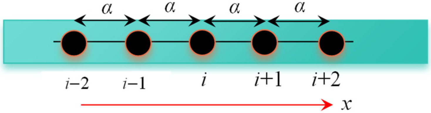
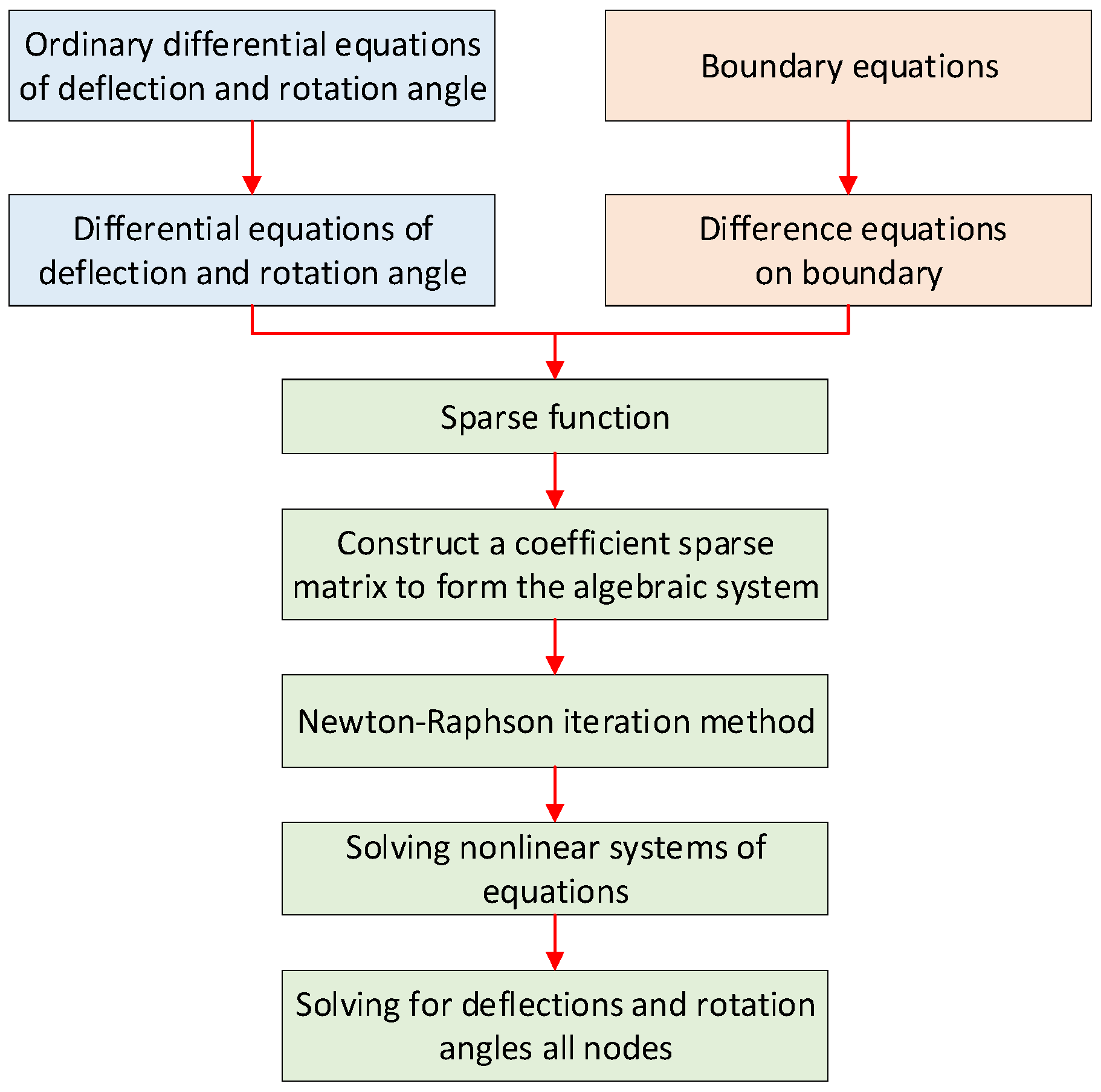
4. Finite Difference Method for a Timoshenko Beam on Winkler Foundation

To calculate the impact load, it is necessary to first obtain the accumulated energy in the HTR. To achieve this, it is required to solve high-order ordinary differential equations for the Timoshenko beam. Due to the complexity of the control equations and boundary conditions for the Timoshenko beam, obtaining analytical solutions is extremely challenging. Therefore, the differential principles are employed to derive differential equations corresponding to the control equations, boundary conditions, and the energy, ultimately solving the challenging problem of determining the PBSD and the energy accumulation-dispersion pattern during the periodic breakage of the HTR.

4.1. Differential Equations of Control Equations

As shown in Figure 8, the Timoshenko beam is discretized along the x-axis with a distance of α between adjacent nodes. Taking the central node i as the reference point, a Taylor expansion is performed for the deflection w and rotation angle ψ in the x-direction, while neglecting higher-order small quantities. This establishes a relationship equation between the deflection w and rotation angle ψ. Substituting the above equation into the control equation, stress equation, boundary equation, failure equation, and energy accumulation equation of the Timoshenko beam, their corresponding difference equations are obtained. The process for solving the deflection w and rotation angle ψ at node i and subsequently solving stress components and energy dissipation values is as follows:
Expanding the deflection w in the x-direction using a Taylor series can be achieved as follows [43]:
w = w ( i ) + w x ( i ) x x ( m ) + 1 2 ! 2 w x 2 ( i ) x x ( i ) 2 + 1 3 ! 3 w x 3 ( i ) x x ( i ) 3 + 1 4 ! 4 w x 4 ( i ) x x ( i ) 4 +
When the other nodes around the central node i are sufficiently close, as shown in Figure 8, the values of x and x i used are not significantly different. In other words, x x ( i ) is small enough. Therefore, it is possible to neglect terms involving x x ( i ) cubed and higher-order terms, simplifying Equation (15) to the following:
w = w ( i ) + w x ( i ) x x ( i ) + 1 2 2 w x 2 ( i ) x x ( i ) 2
At nodes i − 1 and i + 1, x is equal to x ( i ) α and x ( i ) + α , respectively. Therefore, x ( i 1 ) x ( i ) and x ( i + 1 ) x ( i ) are equal to α and α , respectively. Substituting these values into Equation (21), we obtain
w ( i 1 ) = w ( i ) α w x ( i ) + α 2 2 2 w x 2 ( i )
w ( i + 1 ) = w ( i ) + α w x ( i ) + α 2 2 2 w x 2 ( i )
By combining Equations (22) and (23), we can obtain the first and second derivatives w x ( i ) and 2 w x 2 ( i ) of the Timoshenko beam deflection w at node (i, j).
w x ( i ) = w ( i + 1 ) w ( i 1 ) 2 α ,   2 w x 2 ( i ) = 1 α 2 w ( i + 1 ) 2 w ( i ) + w ( i 1 )
Similarly, for the rotation angle ψ, we can obtain
ψ x ( i ) = ψ ( i + 1 ) ψ ( i 1 ) 2 α ,   2 ψ x 2 ( i ) = 1 α 2 ψ ( i + 1 ) 2 ψ ( i ) + ψ ( i 1 )
By substituting Equations (24) and (25) into Equation (9), we obtain the differential form of the control equation for the beam in the cantilever section AO. It forms a system of equations with 3 nodes and 6 parameters:
κ G A 1 α 2 w ( i + 1 ) 2 w ( i ) + w ( i 1 ) ψ ( i + 1 ) ψ ( i 1 ) 2 α = q E I 1 α 2 ψ ( i + 1 ) 2 ψ ( i , j ) + ψ ( i 1 ) κ G A w ( i + 1 ) w ( i 1 ) 2 α ψ ( i ) = 0
Similarly, we obtain the differential form of the control equation for the beam in the plastic section OB. It also forms a system of equations with 3 nodes and 6 parameters:
κ G A 1 α 2 w ( i + 1 ) 2 w ( i ) + w ( i 1 ) ψ ( i + 1 ) ψ ( i 1 ) 2 α + k p w ( i ) = q E I 1 α 2 ψ ( i + 1 ) 2 ψ ( i ) + ψ ( i 1 ) κ G A w ( i + 1 ) w ( i 1 ) 2 α ψ ( i ) = 0
Similarly, the differential form of the control equation for the elastic section BC of the beam is obtained, which is a set of equations with 3 nodes and 6 parameters:
κ G A 1 α 2 w ( i + 1 ) 2 w ( i ) + w ( i 1 ) ψ ( i + 1 ) ψ ( i 1 ) 2 α + k e w ( i ) = q E I 1 α 2 ψ ( i + 1 ) 2 ψ ( i ) + ψ ( i 1 ) κ G A w ( i + 1 ) w ( i 1 ) 2 α ψ ( i ) = 0

4.2. Difference Equations on Boundary

The role of the boundary differential equation is to reduce the number of unknown parameters, making the matrix formed by the differential equations of the control method positive definite, thus enabling the solution of w and ψ of each node.
The external boundary conditions during the HTRs’ periodic breakage are as follows [44]:
x = L 1 , ψ ( i + 1 ) ψ ( i 1 ) = 0 , w ( i + 1 ) w ( i 1 ) 2 α ψ ( i ) = 0 x = L 2 , w ( i ) = 0 , ψ ( i ) = 0
The internal boundary conditions at the elastoplastic boundary (x = L3) during the HTRs’ periodic breakage are as follows:
w 2 ( i ) = w 3 ( i ) ψ 2 ( i ) = ψ 3 ( i ) w 2 ( i + 1 ) w 2 ( i 1 ) 2 α ψ 2 ( i ) = w 3 ( i + 1 ) w 3 ( i 1 ) 2 α ψ 3 ( i ) ψ 2 ( i + 1 ) ψ 2 ( i 1 ) = ψ 3 ( i + 1 ) ψ 3 ( i 1 )

4.3. Difference Equations of the HTRs’ Energy During Periodic Breakage

By substituting Equations (24) and (25) into Equation (15), we obtain the energy density at node i of the beam in the following Equation (31).
U l ( i ) e = 1 2 E E 2 h 3 12 ψ ( i + 1 ) ψ ( i 1 ) 2 α 2 + 6 κ 2 G 2 A 2 5 h w ( i + 1 ) w ( i 1 ) 2 α ψ ( i ) 2
When the stress of the HTR reaches the critical value, the HTR undergoes rupture and the PBSD Lp can be obtained. At this time, the accumulated elastic deformation energy also reaches its peak. When the spacing of the differential is sufficiently small, the energy density of the HTR within the interval α, α U l ( i ) e , can be considered constant, and thus the sum of energy density within many intervals α can be calculated. Therefore, the elastic deformation energy of the HTR before periodic breakage can be calculated by the following formula:
U = α U l ( i ) e
By substituting the accumulated energy of the HTRs’ periodic breakage into Formulas (18) to (19), the hydraulic support at a working face can withstand the impact load, which can be obtained.

4.4. Solving for the HTRs’ Energy During Periodic Breakage

According to Equations (31) and (32), obtaining the energy dissipation values for periodic breakage in the HTR requires first determining the deflection and rotation values for each difference node. This necessitates solving the system of difference equations for deflection and rotation.
Based on the established difference equations as described earlier, it can be noted that in any difference equation, there are at most three unknown nodes for deflection and rotation angle. By setting up 3-node difference equations for each of the unknown deflection and rotation nodes and forming an algebraic system, the deflection solutions for all nodes can be obtained by solving this system of equations. The solving process described above can be implemented using the method shown in Figure 9. This involves using the sparse function in MATLAB R2021b software to construct a coefficient sparse matrix to form the algebraic system. Then, the Newton–Raphson iteration method is called to solve this system of equations, resulting in the deflection and rotation values for all unknown nodes.
Once the deflection and rotation angle values for the nodes are determined, they can be substituted into Equations (31) and (32) to obtain the energy dissipation values for periodic breakage in the HTR.

5. Verification of the Finite Difference Method

The computational method proposed in the paper can be used to solve the PBSD of HTRs and the impact load borne by the hydraulic support. Its accuracy can be validated by comparing the results with measured data.

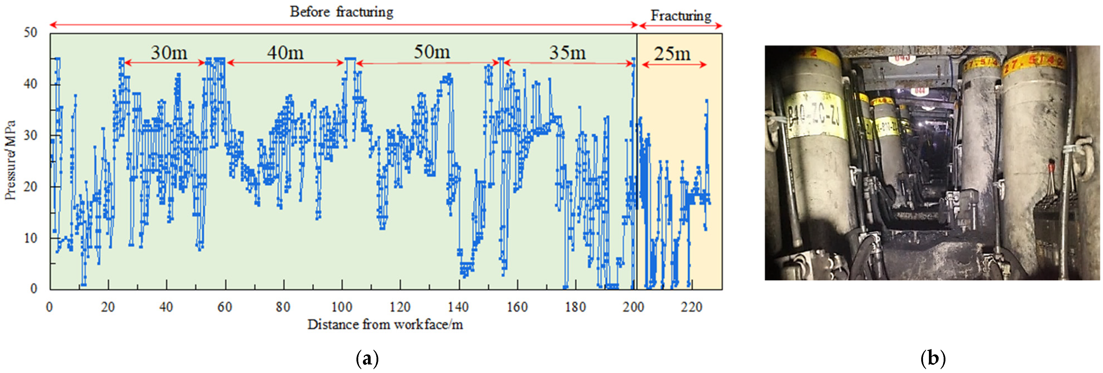
5.1. PBSD of HTR and the Impact Load Borne by Hydraulic Supports

The provided information and parameters describe the conditions for the 61,304 full-mechanized caving working faces in Tangjiahui Coal Mine, from the reference [26]. These conditions include the workface width (L), 240 m; HTR thickness (d) of 15.8 m; tensile strength (σ), 5.5 MPa; elastic modulus (E), 4 GPa; Poisson’s ratio (ν), 0.2; overlying load transferred to the HTR ( p D ), 0.94 MPa; ground stiffness of the coal–rock mass in the mining area (k), 1000 MN/m; ultimate uniaxial compressive strength of the elastic foundation ( σ 01 ), 30 MN/m; corresponding deflection for elastic foundation (w01), 0.01 m; residual strength of the elastic foundation ( σ 02 ), 3.5 MN/m; corresponding deflection for the residual strength (w02), 0.03 m; roof length supported by hydraulic supports (lZJ), 7.0 m; center distance of the support (bZJ), 1.75 m; thickness of the immediate roof (dZJD), 16 m; rock layer fracture angle (β), 70°; average bulk density of the immediate roof (γZJD), 1600 kg/m3; and acceleration due to gravitation (g), 9.8 m/s2.
The HTR typically experiences tensile failure; therefore, it is necessary to solve the differential equations for its maximum tensile stress and peak shear stress. The formula for calculating the maximum tensile stress at node i is as follows:
σ max ( i ) = E h ψ ( i + 1 ) ψ ( i 1 ) 4 α
By iteratively adjusting the PBSD (Lp) using a binary search method until the maximum tensile stress σ max among all nodes reaches 5.5 MPa, a value of Lp equal to 23 m is obtained. Furthermore, by substituting this value into Equations (18), (19), and (26)–(32), the calculated impact load borne by the hydraulic support is determined to be 16,011 kN.

5.2. Comparison of Key Parameters During HTRs’ Periodic Breakage

On-site monitoring was conducted with 65#, 75#, 85#, 95#, and 105# hydraulic supports at this workface. The monitoring data for these sampled supports were statistically analyzed during different time periods (April and June), and the results are presented in Figure 10.
The on-site monitoring results indicate the following: (1) During the periodic breakage, the hydraulic supports at the workface exhibited a resistance increase phenomenon with a pressure of 35~41 MPa and an average of approximately 38 MPa, i.e., 14,600 kN. The interval step distance for increasing resistance was 19~24 m, with an average of 22 m, which shows a difference of 4.5% with the calculated theoretical PBSD of the HTR, 23 m. (2) Regarding the on-site feedback during the mining, the dynamic resistance of the hydraulic supports was measured at 14,600 kN. This value differs by approximately 4.8% from the theoretically calculated one, which was 15,308 kN.
From these results, it can be concluded that the theoretical calculation approach employed in this study shows a high degree of accuracy.

6. Results

The method proposed in the paper enables accurate calculation of the PBSDs of the HTRs and the impact load borne by hydraulic supports, hence demonstrating the accuracy of this method. The HTRGFT essentially weakens the HTRs’ strength and reduces the PBSD. However, the quantitative relationship between the PBSD and the impact load is not clear, making it difficult to accurately understand the control mechanism for dynamic hazards by the HTRGFT. Therefore, this method is initially used to analyze the effect of the cantilever beam length of the HTRs on their bending moment distribution. This information is then used to determine the HTRs’ PBSD with different cantilever beam lengths. Next, the relationship between the periodic breaking step distance and the impact load of the workface is studied. This will help to assess dynamic hazards and reveal the control mechanism of the HTRGFT.

6.1. Research Plan

To begin with, an analysis of the effect of the cantilever beam length of the HTR on its bending moment distribution was conducted, leading to the determination of the PBSD under different cantilever beam lengths. For this purpose, referring to the parameters, we set up the following research scheme [26]: elastic modulus of the HTR, 4.0 GPa; Poisson’s ratio, 0.2; stiffness of the elastic foundation, 1000 MN/m; thickness of the HTR, 10 m; load from the overlying strata, 1.0 MPa; uniaxial tensile strength, 6.5 MPa. The cantilever beam length, with sample points spaced every 5 m, varied from 10 to 30 m, i.e., 10 m, 15 m, 20 m, 25 m, and 30 m, as depicted in Figure 11.

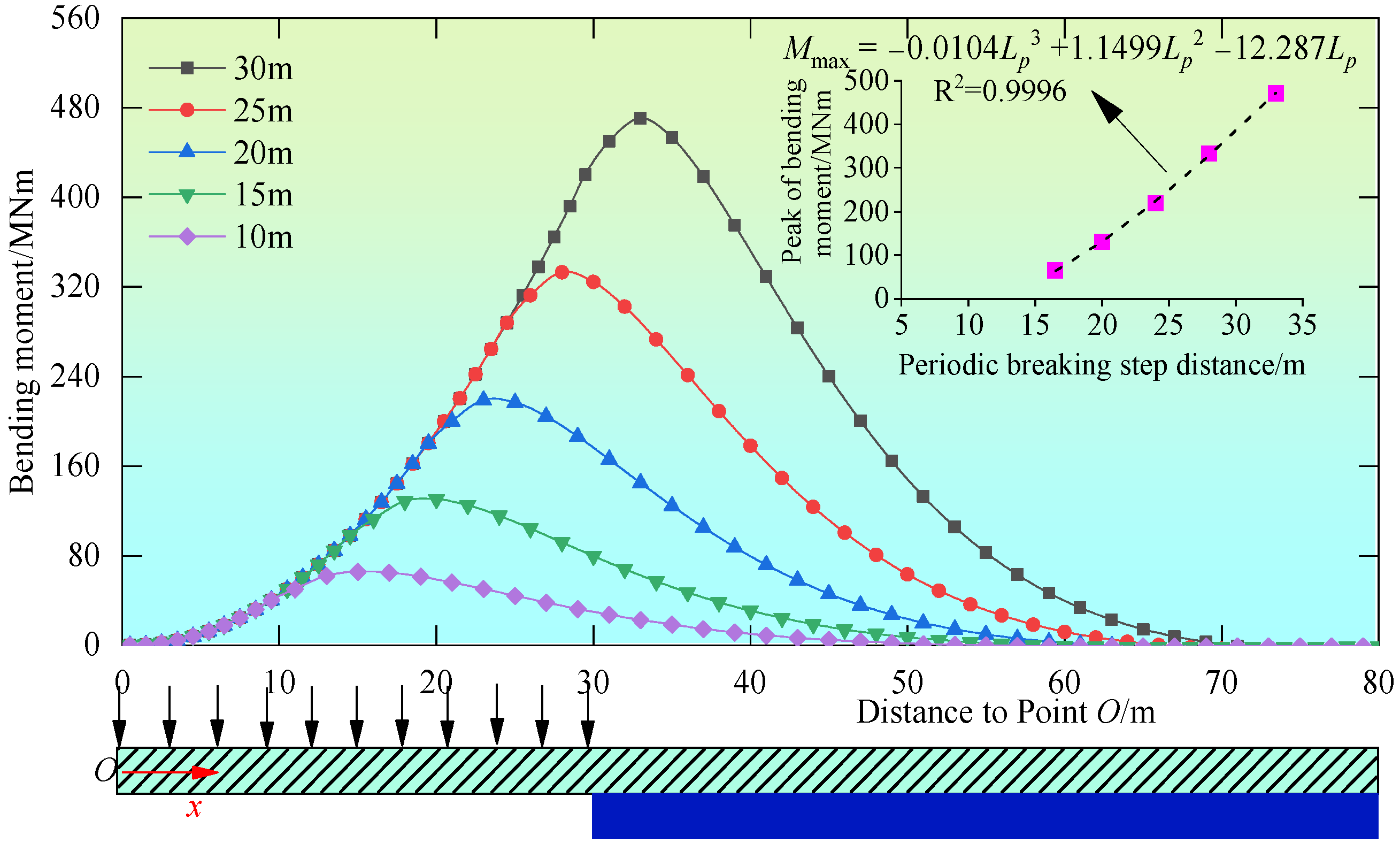
6.2. The Influence of the Cantilever Beam Length of the HTR on the Bending Moment Distribution

The bending moment in the HTR corresponds to tensile/compressive stresses, determining its PBSD. Additionally, tensile stress is a significant component of the elastic deformation energy of the HTR, which has a crucial influence on the impact load experienced at the workface. At the same time, the cantilever beam length of the HTR determines the distribution of bending moments. Therefore, it is necessary to investigate how the cantilever beam length of the HTR during periodic breakage affects the distribution of bending moments and, consequently, determines the PBSD. As shown in Figure 12, the research presents the distribution patterns of bending moments in the HTR for varying cantilever beam lengths.
From Figure 12, the following observations can be made: (1) The bending moment of the HTR follows a single-peaked pattern, increasing initially and then decreasing as the distance from the cantilever endpoint O grows. (2) When the cantilever beam lengths are 10, 15, 20, 25, and 30 m, the HTR reaches its peak bending moment at distances of 16.5, 20.0, 24.0, 28.0, and 33.0 m from the cantilever endpoint O, respectively. This indicates that the fracture position occurs 6.5, 5.0, 4.0, 3.0, and 3.0 m ahead of the working face, with corresponding peak bending moments of 64.8, 130.5, 218.9, 332.9, and 470.6 MN·m. (3) Based on the locations of the peak bending moments, it can be deduced that when the cantilever beam lengths are 10, 15, 20, 25, and 30 m, the PBSDs of the HTR are 16.5, 20.0, 24.0, 28.0, and 33.0 m, respectively. (4) The peak bending moment and the PBSD are related by a cubic function: M max = 0.0104 L p 3 + 1.1499 L p 2 12.28 L p . (5) When the cantilever beam lengths are 10, 15, 20, 25, and 30 m, the bending moment becomes zero at distances exceeding 50.0, 56.0, 61.0, 66.0, and 71.0 m from the cantilever endpoint O, respectively, with corresponding influence distances of periodic breakage of 40, 41, 41, 41, and 41 m ahead of the working face, respectively. This indicates that these positions are not affected by periodic breakage.

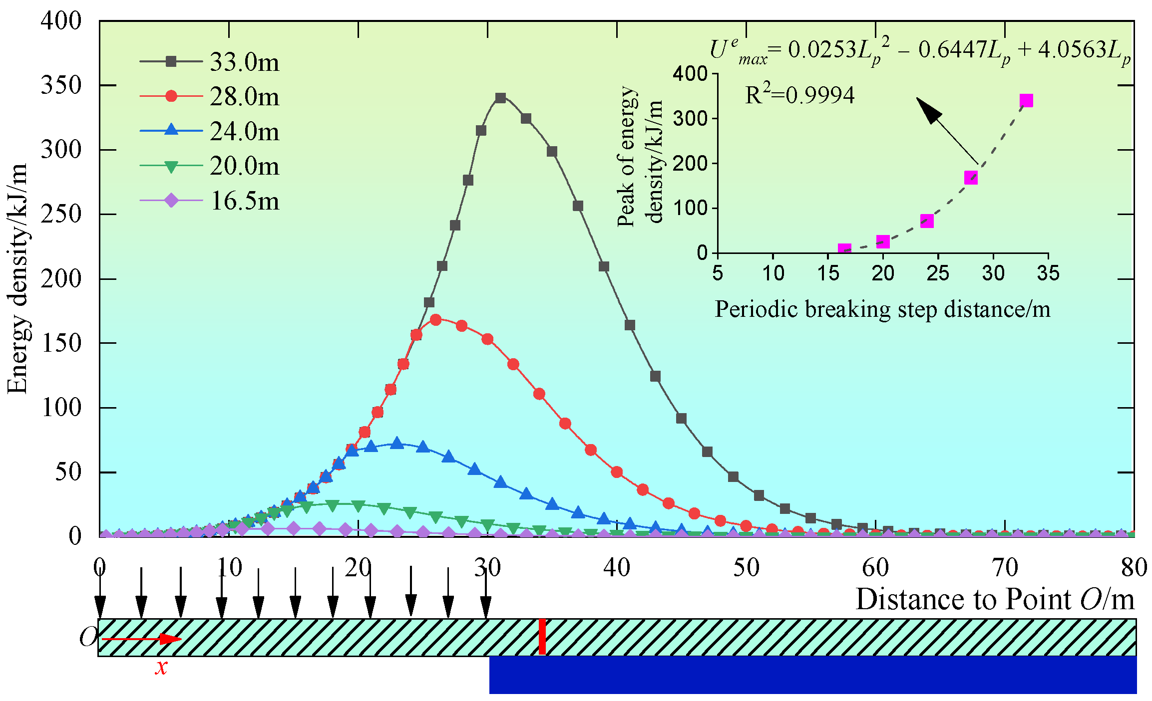
6.3. The Influence of PBSD on the Distribution of Elastic Deformation Energy Density in HTRs

When the elastic deformation energy assembled during the HTRs’ periodic breakage is released, it generates shock vibration, which in turn produces an impact load on the workface. As shown in Figure 13, the distribution law of elastic deformation energy density under different PBSDs is presented.
The following is true according to Figure 13: (1) The elastic deformation energy density of the HTR exhibits a unimodal distribution, increasing initially and then decreasing with the distance from the cantilever endpoint O. (2) When the PBSDs are 16.5, 20.0, 24.0, 28.0, and 33.0 m, respectively, the elastic deformation energy density of the HTR reaches its peak at distances of 15.0, 18.0, 23.0, 26.0, and 31.0 m from the cantilever beam endpoint O, with the corresponding peak values of elastic deformation energy density being 6.5, 25.4, 71.6, 168.2, and 340.1 kJ/m. (3) The maximum of the elastic deformation energy density is composed of a bending deformation moment part and a shear part, and the peak of the elastic deformation energy density does not coincide with the position of the periodic fracture, indicating that the lateral shear deformation cannot be ignored. (4) The peak value of the elastic deformation energy density of the HTR shows a quadratic relationship with the PBSD, with the specific relationship being U max e = 0.0253 L p 3 0.6447 L p 2 + 4.0563 L p . (5) When the PBSDs increases from 16.5 m to 33.0 m, the elastic deformation energy density of the HTR increases by 18.9, 46.2, 96.6, and 171.9 MkJ/m, respectively, indicating that the longer PBSDs, the greater the increase in the elastic deformation energy of the HTR.

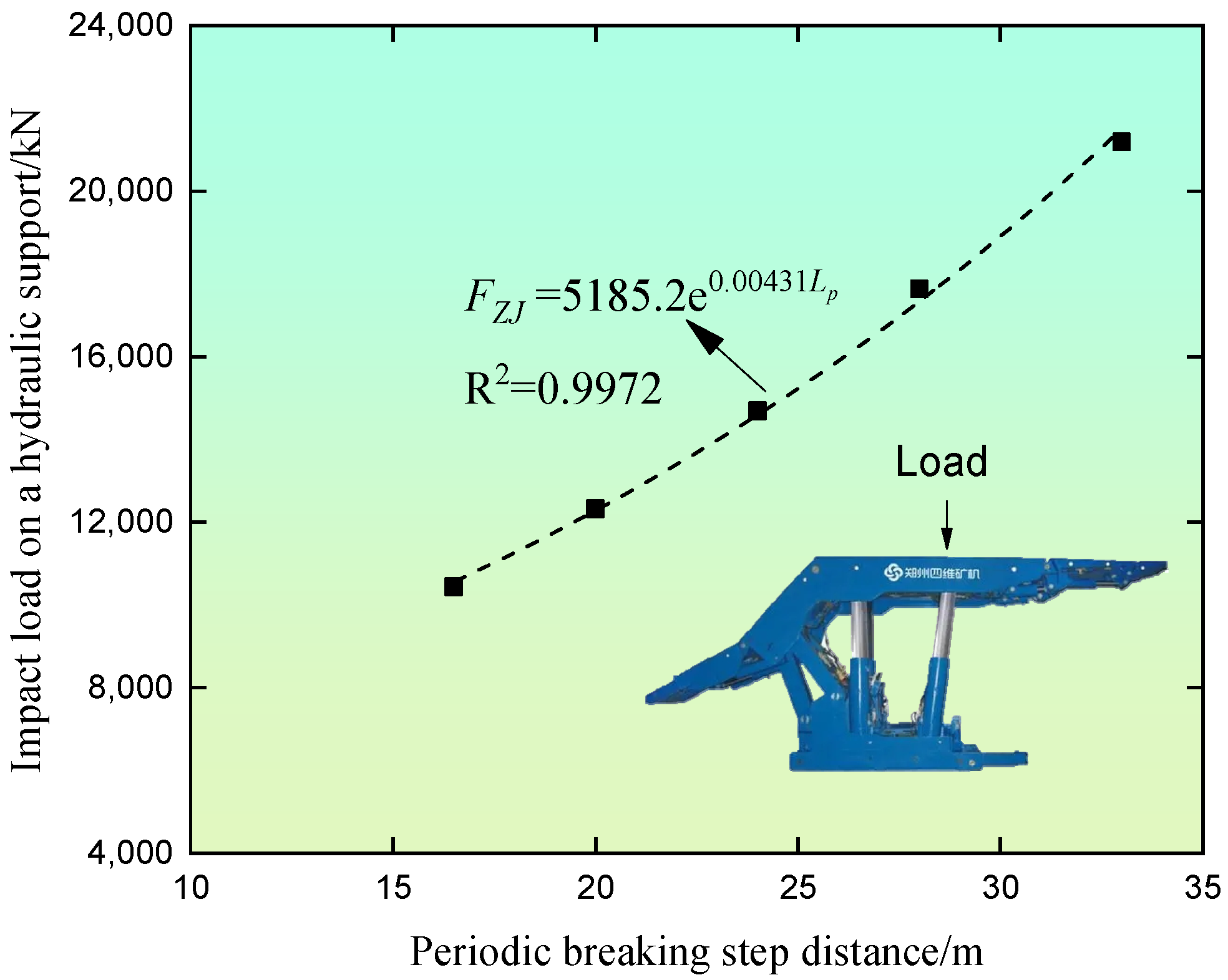
6.4. The Influence of the PBSD on the Impact Load of the Workface

To analyze the influence of the PBSD of the HTR on the impact load of the working face, other parameters are needed beforehand. Here, the hydraulic support’s control distance was set at lZJ = 6 m, with the center-to-center distance between supports bZJ = 1.75 m, the immediate roof thickness is dZJD = 16 m, the rupture angle of the rock layer β = 70°, the average bulk density of the immediate roof γZJD = 1600 kg/m3, and the gravitational acceleration g = 9.8 m/s2. Substituting these parameters into Formula (22), the impact load on the workface under different PBSDs is obtained, as shown in Figure 14.
From Figure 14, the following observations can be made: (1) As the PBSD increases, the impact load also increases, and its increase rate becomes more rapid. Therefore, when the PBSD of the HTR is longer, the impact load carried by the hydraulic support increases significantly more. This implies a higher risk of the occurrence of workface impact disasters. (2) When the PBSDs are 16.5, 20.0, 24.0, 28.0, and 33.0 m, the corresponding impact loads borne by the hydraulic supports are 10,442, 12,324, 14,692, 17,634, and 21,186 kN, respectively. (3) The relationship between the impact load and the PBSD follows an exponential function, with a specific mathematical relationship, F Z J = 5185.2 e 0.00431 L p .
According to these results, it can be concluded that reducing the PBSD in the HTR can effectively control the impact load on the workface. This has important implications for ensuring personal safety.

7. Discussions

The HTRGFT weakens the strength of the HTR, reducing the PBSDs at their periodic breakage, and it is concluded that this can effectively control dynamic hazards at the working face. The 8218 Workface, an isolated working face in Tashan Coal Mine, was used as an example to analyze the PBSD of the HTR and the impact load on the hydraulic support before and after ground fracturing, as well as to evaluate the effectiveness of the HTRGFT control method.
8218 Workface parameters: the width of the working face, L = 240 m, with a recoverable length of 1797 m; roof length supported by hydraulic supports, lZJ = 7.0 m; the hydraulic supports center distance, bZJ = 1.75 m; rated working resistance of the hydraulic support, 15,000 kN; thickness of the HTR, h = 10 m; load borne by the HTR, 1.0 MPa, considering HTR’s self-weight and the overlying 30-m thick weak rock according to the key layer theory; the strata thickness of the immediate roof, dZJD = 12 m; the immediate roof average bulk density, γZJD = 1600 kg/m3; rock layer rupture angle, β = 70°; gravity acceleration, g = 9.8 m/s2.
The HTRGFT’s process steps for the 8218 Workface include drilling, perforation, and fracturing, as shown in Figure 15 with the specific parameters as follows:
(1)
Drilling. Using a three-cone bit and screw drill bit for construction, drilling is completed in three stages. First stage uses a Φ444.5 mm drill bit to drill to a depth of 50 m and then lower it, and to cement a Φ339.7 × 9.65 mm casing; in the next stage, a Φ311.5 mm drill bit Manufactured by Shijiazhuang Shanlang Technology Co., Ltd., Shijiazhuang, China is used to drill to a depth of 128 m, and then a Φ244.5 × 8.94 mm casing is lowered and cemented; then, a Φ216 mm drill bit is used to drill to the target fracturing layer at 772 m, and a Φ139.7 × 7.72 mm casing is lowered, with a horizontal well length of 700 m.
(2)
Perforation. The selected perforation process is used, i.e., connecting a downhole perforating gun with a cable, lowering the tool string into the well under a closed construction state, reaching the target layer, and lifting the cable to ignite and complete multiple clusters of perforation. The perforating gun model is 89-16DP-60-105, with an outer diameter of 89 mm, hole density of 16 per/m, and working pressure of 105 MPa; the perforating bullet model is SDP41RDX25-2, with RDX (Hexogen) selected as the explosive.
(3)
Fracturing. Hydraulic fracturing involves using high-pressure pump trucks on the surface to inject fluid at high speed into the well, generating high pressure at the well’s bottom. This pressure fractures the rock layer, creating cracks. When gas extraction from underground is required through surface operations, liquid is injected into the fractured formation after the pump truck stops. To prevent pressure from dropping and the cracks from closing, sand—much denser than the formation—is mixed with the fluid. The sand enters the cracks and remains there permanently, keeping the cracks open.
The ability to create a specific fracture system pattern at designated spatial locations within HTRs is crucial for the success of horizontal well fracturing. It is also one of the core challenges that need to be addressed in the HTRGFT. For example, it involves determining whether the fracture propagation can penetrate HTRs vertically and cover the entire workface horizontally. Currently, monitoring the fracture expansion of the HTRGFT often involves deploying monitoring seismometers on the ground. These seismometers detect the locations of microseismical events to assess the extent of fracture propagation at different stages of the fracturing process. As shown in Figure 15, (1) seismic detectors and monitoring stations are placed around the well to receive underground microseismical signals. (2) High-precision models are obtained through iterative inversion based on the pickup of effective signals. (3) The propagation characteristics of elastic wavefields in subsurface media are used, and techniques such as ray tracing, pre-stack migration, and high-fold stacking are applied to locate microseismical data in the target layer. (4) Utilizing both longitudinal and shear wave characteristics of the collected signals, as well as seismic imaging, comprehensive interpretations are made regarding factors such as seismic magnitude, waveform characteristics, polarization direction, relationships between longitudinal and shear waves, frequency characteristics, etc. These interpretations provide foundational data for inferring the morphology and extent of fracture propagation. Microseismic monitoring and inversion techniques play a critical role in determining the shape and range of fracture propagation in the HTRGFT, addressing one of the key challenges in the HTRGFT.
The fracturing drilling was arranged in the middle of the overlying 10-m HTR, as shown in Figure 16a. To accurately monitor the expansion of fractures, microseismic monitoring technology was employed during the hydraulic fracturing process at the 8218 Workface. The extension range of fractures obtained from the inversion analysis is shown in Figure 16b. As shown in Figure 17, the resistance of the central 68# hydraulic support before and after hydraulic fracturing was statistically analyzed to determine the PBSD of the HTR.
From Figure 17, the following observations can be made: (1) In the area where HTRGFT was not conducted, the PBSD of the HTR ranged from 35 to 50 m. However, within the hydraulic fracturing area, the PBSD decreased to 25 m. This indicates that the HTRGFT can indeed reduce the PBSD, thereby controlling the hydraulic support impact load in the workface and achieving the goal of preventing dynamic disasters. (2) According to the method proposed in this paper, the impact load borne by hydraulic support before hydraulic fracturing should range from 20,809 to 47,914 kN. And it can reduce to 13,713 kN after hydraulic fracturing. However, the on-site measured impact load before hydraulic fracturing was consistently 15,000 kN, and the hydraulic supports experienced jamming, as shown in Figure 17b. The reason for the deviation between the measured and theoretical calculations was the pressure relief valve of the hydraulic supports, i.e., its working resistance controls the maximum working resistance of the supports. In fact, in the hydraulic fracturing zone, the measured working resistance of the hydraulic supports was 13,500 kN, which deviated from the theoretical calculation by 1.6%.
Based on these findings, it can be concluded that the HTRGFT weakens the strength of HTRs and effectively reduces the PBSD. This, in turn, enables the control of the impact load on the workface, thereby preventing mine earthquake disasters in the workface.
Although the theoretical model demonstrates good compatibility in both theoretical analysis and engineering applications, natural rock materials often contain widespread joints and fractures. These joints and fractures significantly reduce the strength of the rock mass, leading to deviations in the calculation results. Additionally, parameters such as the supporting performance of the coal seam, degree of plastification, elastic modulus, and Poisson’s ratio of the HTR have not been studied or discussed in detail, and further research in this area could be conducted in the future.

8. Conclusions

This study established a Timoshenko beam model on a Winkler foundation incorporating the elastoplasticity and strain-softening behavior of coal–rock masses, providing a more reliable theoretical basis for the prevention and control of mine earthquake disasters. It also employed ground fracturing to weaken the strength of the roof, reducing its periodic breakage step distance, thereby effectively controlling the impact load and dynamic hazards at the working face.
(1)
This paper proposes a boundary treatment method that considers the elastoplastic and strain-softening mechanical behavior of coal–rock masses, establishes a stiffness calculation formula for the coal–rock mass during compression, constructs a Timoshenko beam model on a Winkler foundation for the energy concentration and dispersion during the HTRs’ periodic breakage, and then derives differential equations of control equations, stress components, boundary conditions, and energy, ultimately providing a method for calculating the PBSD of the HTR and the impact load on hydraulic supports.
(2)
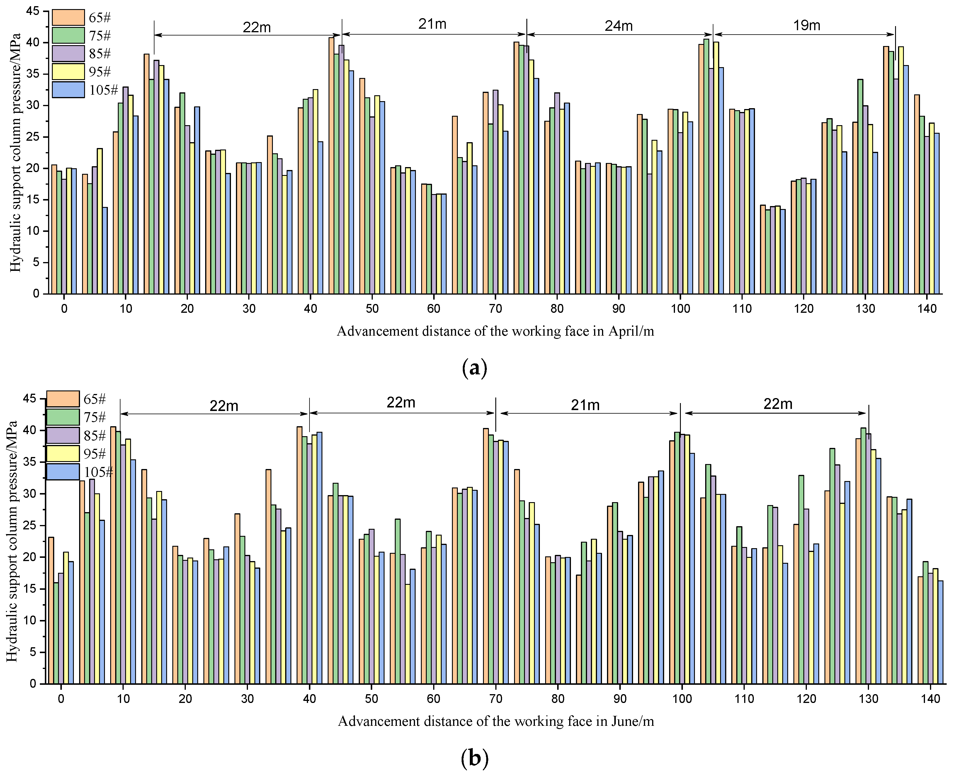
Based on the method proposed in this paper, it was calculated that the periodic breaking step distance is 23 m for the 15.8 m thick HTR of the 61,304 Workface full-mechanized caving workface in the Tangjiahui coal mine, and that the impact load on the hydraulic support is 15,308 kN. These results differ from the on-site measured data by 4.5% and 4.8% respectively, thus proving the accuracy of the method proposed in the paper.
(3)
During the periodic breakage, both the distribution of the bending moment and the elastic deformation energy density of the HTR showed a unimodal pattern, with their peak values being 1.0 to 6.5 m ahead of the cantilever endpoint O, while the positions where the bending moment and elastic deformation energy density are zero are 40 to 41 m ahead of the cantilever endpoint O, thus determining the breaking position of the HTR and the area of advanced influence.
(4)
During the periodic break, the relationship between the PBSD and the peak values of the bending moment and elastic deformation energy density of the HTR is cubic, while its relationship with the impact load on the hydraulic support is exponential, that is, F Z J = 5185.2 e 0.00431 L p .
(5)
The comparative evaluation of theoretical calculation and measured results shows that reducing the HTRs’ PBSD is one of the best ways to control impact load. The HTRGFT weakens the HTR’ strength, reducing its periodic breaking step distance, thus effectively controlling the impact load on the workface and avoiding the occurrence of mine earthquake disasters.

Author Contributions

Conceptualization, B.Y. and Y.T.; methodology, M.P.; software, Y.T.; validation, M.P., B.Y. and Y.T.; formal analysis, Y.T.; investigation, F.G.; resources, F.G.; data curation, F.G.; writing—original draft preparation, F.G.; writing—review and editing, X.M.; visualization, X.M.; supervision, X.M.; project administration, X.M.; funding acquisition, F.G. All authors have read and agreed to the published version of the manuscript.

Funding

This research was funded by the Autonomous General Projects of State Key Laboratory of Coal Mine Disaster Dynamics and Control (2011DA105287-MS202209), the Faces the 2030 Project of State Key Laboratory of Coal Mine Disaster Dynamics and Control (2011DA105287-MX2030-202002), and the Chongqing Municipal Special Postdoctoral Support (2022CQBSHTB1022).

Data Availability Statement

The data presented in this study are openly available in [Drayd] at [DOI: 10.5061/dryad.1jwstqk54].

Conflicts of Interest

The authors declare no conflicts of interest.

Abbreviations

The following abbreviations are used in this manuscript:
HTRsHard–thick roofs
HTRGFTHard–thick roof ground hydraulic fracturing technology
PBSDthe periodic breaking step distance

References

  1. Xie, S.-R.; Chen, D.-D.; Sun, Y.-D.; Gao, M.-M.; Sun, Y.-J.; Shi, W. Analysis on thin plate model of basic roof at elastic foundation boundary(I): First breaking. J. China Coal Soc. 2016, 41, 1360–1368. [Google Scholar]
  2. Du, J.; Chen, J.; Pu, Y.; Jiang, D.; Chen, L.; Zhang, Y. Risk assessment of dynamic disasters in deep coal mines based on multi-source, multi-parameter indexes, and engineering application. Process Saf. Environ. Prot. 2021, 155, 575–586. [Google Scholar] [CrossRef]
  3. Zheng, J.; Huang, G.; Cheng, Q.; Jia, J.; Cai, Z. A Novel Experimental Apparatus for Evaluating Coal-and-Gas Outburst Risk. Nat. Resour. Res. 2022, 31, 535–550. [Google Scholar] [CrossRef]
  4. Ning, J.; Wang, J.; Jiang, L.; Jiang, N.; Liu, X.; Jiang, J. Fracture analysis of double-layer hard and thick roof and the controlling effect on strata behavior: A case study. Eng. Fail Anal. 2017, 81, 117–134. [Google Scholar] [CrossRef]
  5. Wang, K.; Zhang, X.; Wang, L.; Li, L.; Zhang, M.; Zhou, A. Experimental study on propagation law of shock wave and airflow induced by coal and gas outburst in mine ventilation network. Process Saf. Environ. Prot. 2021, 151, 299–310. [Google Scholar] [CrossRef]
  6. Zhou, A.; Fan, L.; Wang, K.; Elsworth, D. Multiscale modeling of shock wave propagation induced by coal and gas outbursts. Process Saf. Environ. Prot. 2019, 125, 164–171. [Google Scholar] [CrossRef]
  7. Zhang, Q.; Wang, E.; Feng, X.; Wang, C.; Qiu, L.; Wang, H. Assessment of Rockburst Risk in Deep Mining: An Improved Comprehensive Index Method. Nat. Resour. Res. 2021, 30, 1817–1834. [Google Scholar] [CrossRef]
  8. Liu, B.; Zhao, Y.; Wang, H.; Gao, Y.; Sun, Z. Tensile Properties and Multiparameter Response Characteristics of Coal under Different Loading Rates. Nat. Resour. Res. 2022, 31, 2787–2803. [Google Scholar] [CrossRef]
  9. Li, S.; You, M.; Li, D.; Liu, J. Identifying coal mine safety production risk factors by employing text mining and Bayesian network techniques. Process Saf. Environ. Prot. 2022, 162, 1067–1081. [Google Scholar] [CrossRef]
  10. Zhou, A.; Wang, K.; Feng, T.; Wang, J.; Zhao, W. Effects of fast-desorbed gas on the propagation characteristics of outburst shock waves and gas flows in underground roadways. Process Saf. Environ. Prot. 2018, 119, 295–303. [Google Scholar] [CrossRef]
  11. Lu, S.; Wang, C.; Liu, Q.; Zhang, Y.; Liu, J.; Sa, Z.; Wang, L. Numerical assessment of the energy instability of gas outburst of deformed and normal coal combinations during mining. Process Saf. Environ. Prot. 2019, 132, 351–366. [Google Scholar] [CrossRef]
  12. Li, Z.-Q.; Xue, Y.; Li, G.; Qiu, D.; Xu, L.; Liu, Q.; Fu, K. Probabilistic determination and application of rock thickness resisting water inrush from karst cave. Process Saf. Environ. Prot. 2023, 172, 462–472. [Google Scholar] [CrossRef]
  13. Fu, G.; Xie, X.; Jia, Q.; Tong, W.; Ge, Y. Accidents analysis and prevention of coal and gas outburst: Understanding human errors in accidents. Process Saf. Environ. Prot. 2020, 134, 1–23. [Google Scholar] [CrossRef]
  14. Li, B.; Wang, E.; Shang, Z.; Liu, X.; Li, Z.; Dong, J. Deep learning and heterogeneous signal fusion approach to precursor feature recognition and early warning of coal and gas outburst. Process Saf. Environ. Prot. 2023, 178, 995–1008. [Google Scholar] [CrossRef]
  15. He, J.; Dou, L.-M.; Mu, Z.-L.; Cao, A.-Y.; Gong, S.-Y. Numerical simulation study on hard-thick roof inducing rock burst in coal mine. J. Cent. South Univ. 2016, 23, 2314–2320. [Google Scholar] [CrossRef]
  16. Li, Q.; Li, Q.C.; Cao, H.Q.; Wu, J.J.; Wang, F.L.; Wang, Y.L. The Crack Propagation Behaviour of CO2 Fracturing Fluid in Unconventional Low Permeability Reservoirs: Factor Analysis and Mechanism Revelation. Processes 2025, 13, 159. [Google Scholar] [CrossRef]
  17. Yu, B.; Tai, Y.; Kuang, T.; Gao, R.; Yang, J.; Xia, B.; Zhu, W.; Li, Y. Theory and technical system of control of far-near field hard roofs from ground and underground in a large space stope. J. China Coal Soc. 2023, 48, 1875–1893. [Google Scholar] [CrossRef]
  18. He, Z.-L.; Lu, C.-P.; Zhang, X.-F.; Guo, Y.; Meng, Z.-H.; Xia, L. Numerical and Field Investigations of Rockburst Mechanisms Triggered by Thick-Hard Roof Fracturing. Rock Mech. Rock Eng. 2022, 55, 6863–6886. [Google Scholar] [CrossRef]
  19. Zuo, J.; Yu, M.; Sun, Y.; Wu, G. Analysis of fracture mode transformation mechanism and mechanical model of rock strata with different thicknesses. J. China Coal Soc. 2023, 48, 1449–1463. [Google Scholar] [CrossRef]
  20. Pan, J.; Kang, H.; Yan, Y.; Ma, X.; Ma, W.; Lu, C.; Lu, D.; Xu, G.; Feng, M.; Xia, Y.; et al. The method, mechanism and application of preventing rock burst by artificial liberation layer of roof. J. China Coal Soc. 2023, 48, 636–648. [Google Scholar] [CrossRef]
  21. Zhou, N.; Xu, J.; Zhang, J.; Ma, D.; Li, Z.; Yao, Y. Study on the weakening mechanism of hard overburden rock burst disaster by backfilling. Chin. J. Rock Mech. Eng. 2023, 42, 2412–2415. [Google Scholar] [CrossRef]
  22. Xu, B.; Xu, W.; Zhang, Y. Experimental Study on the Characteristics of Overlying Rock Movement in Mining Area. Geotech. Geol. Eng. 2023, 42, 1779–1791. [Google Scholar] [CrossRef]
  23. Li, Y.; Tai, Y.; Yu, B.; Kuang, T.; Gao, R.; Liu, J. Evolution and control technology of energy aggregation and dissipation of a high hard roof during breakage and destabilization. Int. J. Fract. 2023, 245, 1–23. [Google Scholar] [CrossRef]
  24. Chen, F.; Liang, Z.; Cao, A. ConvLSTM for Predicting Short-Term Spatiotemporal Distribution of Seismic Risk Induced by Large-Scale Coal Mining. Nat. Resour. Res. 2023, 32, 1459–1479. [Google Scholar] [CrossRef]
  25. Zhao, S.; Sui, Q.; Cao, C.; Wang, X.; Wang, C.; Zhao, D.; Wang, Y.; Zhao, Y. Mechanical model of lateral fracture for the overlying hard rock strata along coal mine goaf. Geomech. Eng. 2021, 27, 75–85. [Google Scholar] [CrossRef]
  26. Zhao, T.; Liu, C.; Yetilmezsoy, K.; Zhang, B.; Zhang, S. Fractural structure of thick hard roof stratum using long beam theory and numerical modeling. Environ. Earth Sci. 2017, 76, 751. [Google Scholar] [CrossRef]
  27. Huang, B.; Wang, Y.; Cao, S. Cavability control by hydraulic fracturing for top coal caving in hard thick coal seams. Int. J. Rock Mech. Min. Sci. 2015, 74, 45–57. [Google Scholar] [CrossRef]
  28. Ramstad, R.K.; Hilmo, B.O.; Brattli, B.; Skarphagen, H. Ground source energy in crystalline bedrock-increased energy extraction using hydraulic fracturing in boreholes. Bull. Eng. Geol. Environ. 2007, 66, 493–503. [Google Scholar] [CrossRef]
  29. Wu, Q.; Jiang, J.; Wu, Q.; Xue, Y.; Kong, P.; Gong, B. Study on the Fracture of Hard and Thick Sandstone and the Distribution Characteristics of Microseismic Activity. Geotech. Geol. Eng. 2018, 36, 3357–3373. [Google Scholar] [CrossRef]
  30. Lyu, S.; Wang, S.; Chen, X.; Wang, S.; Wang, T.; Shi, X.; Dong, Q.; Li, J. Natural fractures in soft coal seams and their effect on hydraulic fracture propagation: A field study. J. Pet. Sci. Eng. 2020, 192, 107255. [Google Scholar] [CrossRef]
  31. Bazoune, A. Combined influence of rotary inertia and shear coefficient on flexural frequencies of Timoshenko beam: Numerical experiments. Acta Mech. 2023, 234, 4997–5013. [Google Scholar] [CrossRef]
  32. Yee, K.; Khaniki, H.B.; Ghayesh, M.H.; Ng, C.T. Free vibrations of cracked functionally graded graphene platelets reinforced Timoshenko beams based on Hu-Washizu-Barr variational method. Eng. Struct. 2023, 293, 116587. [Google Scholar] [CrossRef]
  33. Alibert, J.J.; Barchiesi, E.; dell’Isola, F.; Seppecher, P. A Class of One Dimensional Periodic Microstructures Exhibiting Effective Timoshenko Beam Behavior. ESAIM Control. Optim. Calc. Var. 2023, 29, 53. [Google Scholar] [CrossRef]
  34. Simoncelli, M.; Zucca, M.; Stochino, F. Fire Resistance of Steel Rack Frames: Assessment, Reinforcement and Collapse Mitigation Strategies. Fire Technol. 2024, 1664, 1–23. [Google Scholar] [CrossRef]
  35. Shakya, N.K.; Padhee, S.S. Asymptotic analysis of Timoshenko-like orthotropic beam with elliptical cross-section. Eur. J. Mech.-ASolids 2023, 102, 105100. [Google Scholar] [CrossRef]
  36. Cao, G.W.; Chian, S.C.; Ding, X.M.; Luan, L.B.; Zheng, C.J.; Zhou, P. Horizontal Static Impedances for OWT Monopiles Based on Timoshenko Beam Theory. Int. J. Geomech. 2023, 23, 04023202. [Google Scholar] [CrossRef]
  37. Singh, B.; Mukhopadhyay, S. Thermoelastic vibration of Timoshenko beam under the modified couple stress theory and the Moore-Gibson-Thompson heat conduction model. Math Mech. Solids 2023, 29, 436–451. [Google Scholar] [CrossRef]
  38. Benzid, A.; Tati, A. Static and buckling behaviors analysis of FG beams using a three unknowns finite element based on enhanced Timoshenko theory. Mech. Adv. Mater. Struc. 2023, 31, 9322–9333. [Google Scholar] [CrossRef]
  39. Chen, D.; Wu, X.; Xie, S.; Sun, Y.; Zhang, Q.; Wang, E.; Sun, Y.; Wang, L.; Li, H.; Jiang, Z.; et al. Study on the Thin Plate Model with Elastic Foundation Boundary of Overlying Strata for Backfill Mining. Math. Probl. Eng. 2020, 2020, 8906091. [Google Scholar] [CrossRef]
  40. He, F.; He, W.; Chen, D.; Xie, S.; Li, H.; He, C. First fracture structure characteristics of main roof plate considering elastic-plastic deformation of coal. J. China Coal Soc. 2020, 45, 2704–2717. [Google Scholar] [CrossRef]
  41. Chen, D.; Wu, Y.; Xie, S.; He, F.; Sun, Y.; Shi, S.; Jiang, Z. Study on the first fracture of the main roof plate structure with one side goaf and elastic-plastic foundation boundary. J. China Coal Soc. 2021, 46, 3090–3105. [Google Scholar] [CrossRef]
  42. Safari, M.; Mohammadimehr, M.; Ashrafi, H. Forced vibration of a sandwich Timoshenko beam made of GPLRC and porous core. Struct. Eng. Mech. 2023, 88, 1–12. [Google Scholar] [CrossRef]
  43. Borri, A.; Carravetta, F.; Palumbo, P. Quadratized Taylor series methods for ODE numerical integration. Appl. Math. Comput. 2023, 458, 128237. [Google Scholar] [CrossRef]
  44. Yadav, M.; Sadasivan, A.L. Taylor series solutions for area ratio and Prandtl-Meyer inverses using differential transform method. Int. J. Adv. Eng. Sci. Appl. Math. 2023, 15, 110–114. [Google Scholar] [CrossRef]
Figure 1. Impact ground pressure of HTRs.
Processes 13 00919 g001
Figure 2. HTR ground fracturing technology. (a) Before the advancement of a workface. (b) After the advancement of a workface.
Processes 13 00919 g002
Figure 3. Weakening mechanism of ground fracturing in HTRs. (a) Acidic corrosion effect. (b) Artificial fractures in HTRs.
Processes 13 00919 g003
Figure 4. Mechanical model for periodic breakage of HTRs.
Processes 13 00919 g004
Figure 5. Internal force relationships of a Timoshenko beam on a Winkler foundation.
Processes 13 00919 g005
Figure 6. Periodic breaking mechanics model of HTRs. (a) Fixed boundary. (b) Elastic support boundary. (c) Elastic–plastic support boundary I. (d) Elastic–plastic support boundary II.
Processes 13 00919 g006
Figure 7. Elastic–plastic coal–rock strata support model. (a) Strain-softening model of coal–rock strata. (b) Equivalent elastic–plastic stiffness model.
Processes 13 00919 g007
Figure 8. Node numbers.
Processes 13 00919 g008
Figure 9. The process of solving for deflections and rotations at nodes in the HTR during periodic breakage.
Processes 13 00919 g009
Figure 10. Hydraulic support resistance [26]. (a) April; (b) June.
Processes 13 00919 g010
Figure 11. Research plan.
Processes 13 00919 g011
Figure 12. Distribution patterns of HTRs’ bending moments with varying cantilever beam lengths.
Processes 13 00919 g012
Figure 13. Distribution law of elastic deformation energy density during the HTRs’ periodic breakage.
Processes 13 00919 g013
Figure 14. Impact load on hydraulic supports under different cantilever beam lengths.
Processes 13 00919 g014
Figure 15. Monitoring method for horizontal well fracturing. (a) Layout of detectors and monitoring stations; (b) radio detector; (c) monitoring stations; (d) signal processing system; (e) microseismical events; (f) range of fracture propagation.
Processes 13 00919 g015
Figure 16. Layout of hydraulic fracturing and monitoring of fracture expansion at the Workface. (a) Layout of the well. (b) Range of crack expansion.
Processes 13 00919 g016
Figure 17. Mining pressure in the 8128 Workface. (a) Hydraulic support resistance. (b) Hydraulic support status.
Processes 13 00919 g017
Disclaimer/Publisher’s Note: The statements, opinions and data contained in all publications are solely those of the individual author(s) and contributor(s) and not of MDPI and/or the editor(s). MDPI and/or the editor(s) disclaim responsibility for any injury to people or property resulting from any ideas, methods, instructions or products referred to in the content.

