Effect of Orientation and Aspect Ratio of an Internal Flat Plate on Natural Convection in a Circular Enclosure

 and
and
Abstract
:1. Introduction
2. Numerical Setup
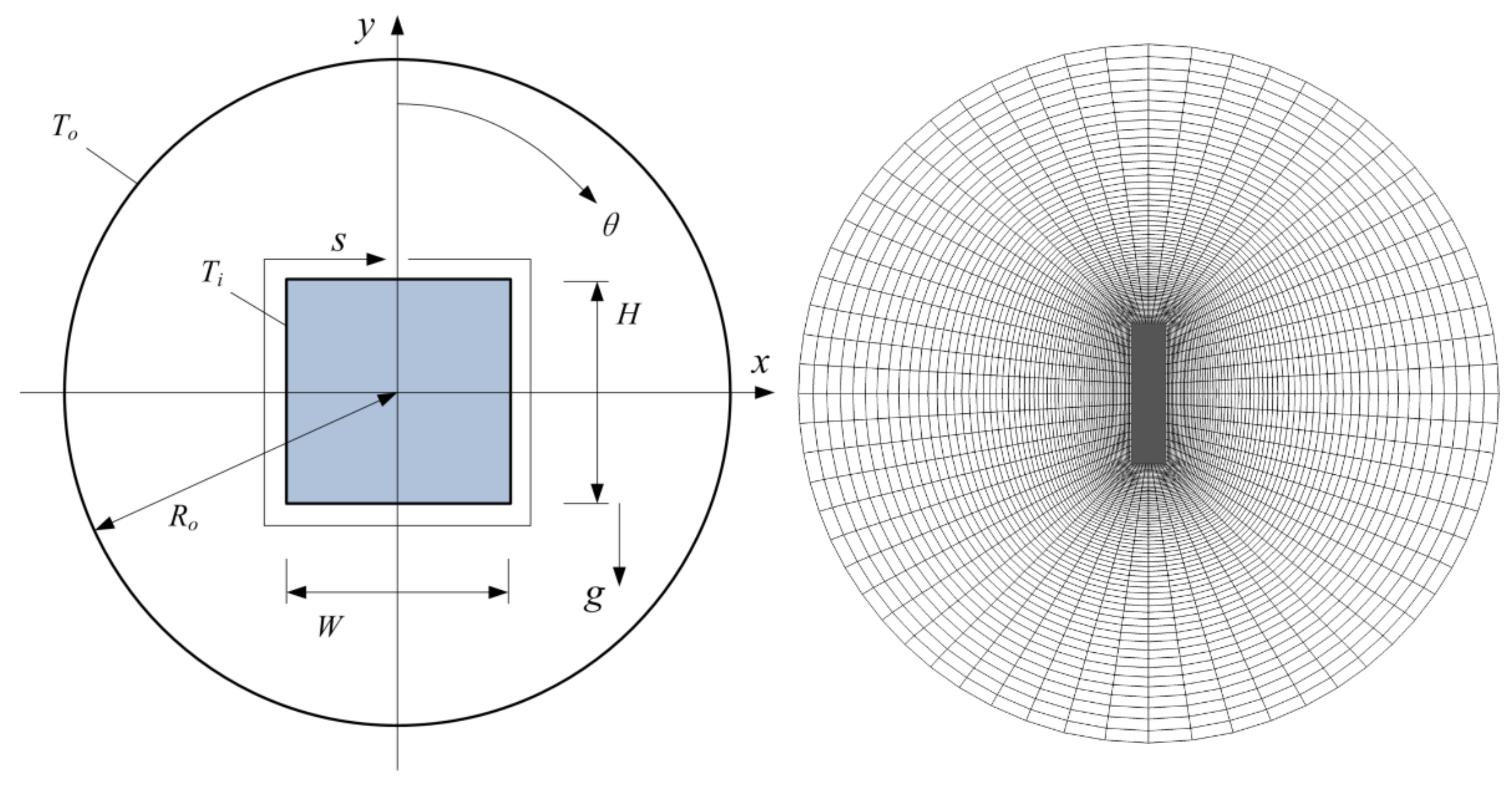
2.1. Physical Model
2.2. Numerical Methods
3. Results and Discussion
3.1. Mean Heat Transfer
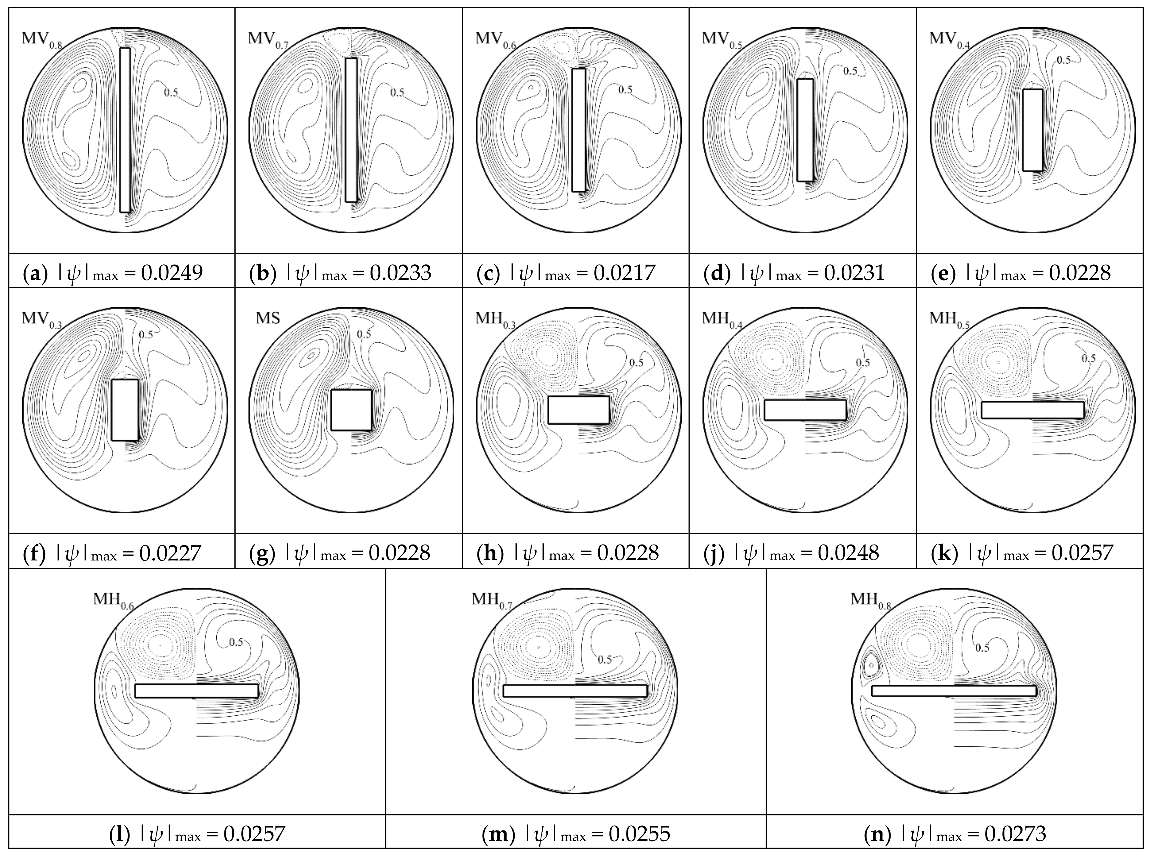
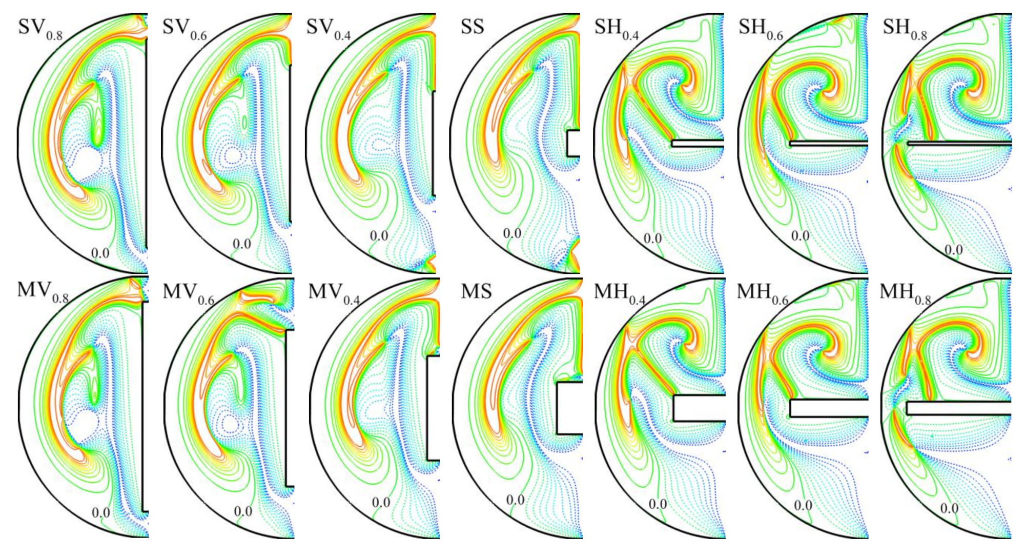
3.2. Thermal and Flow Patterns
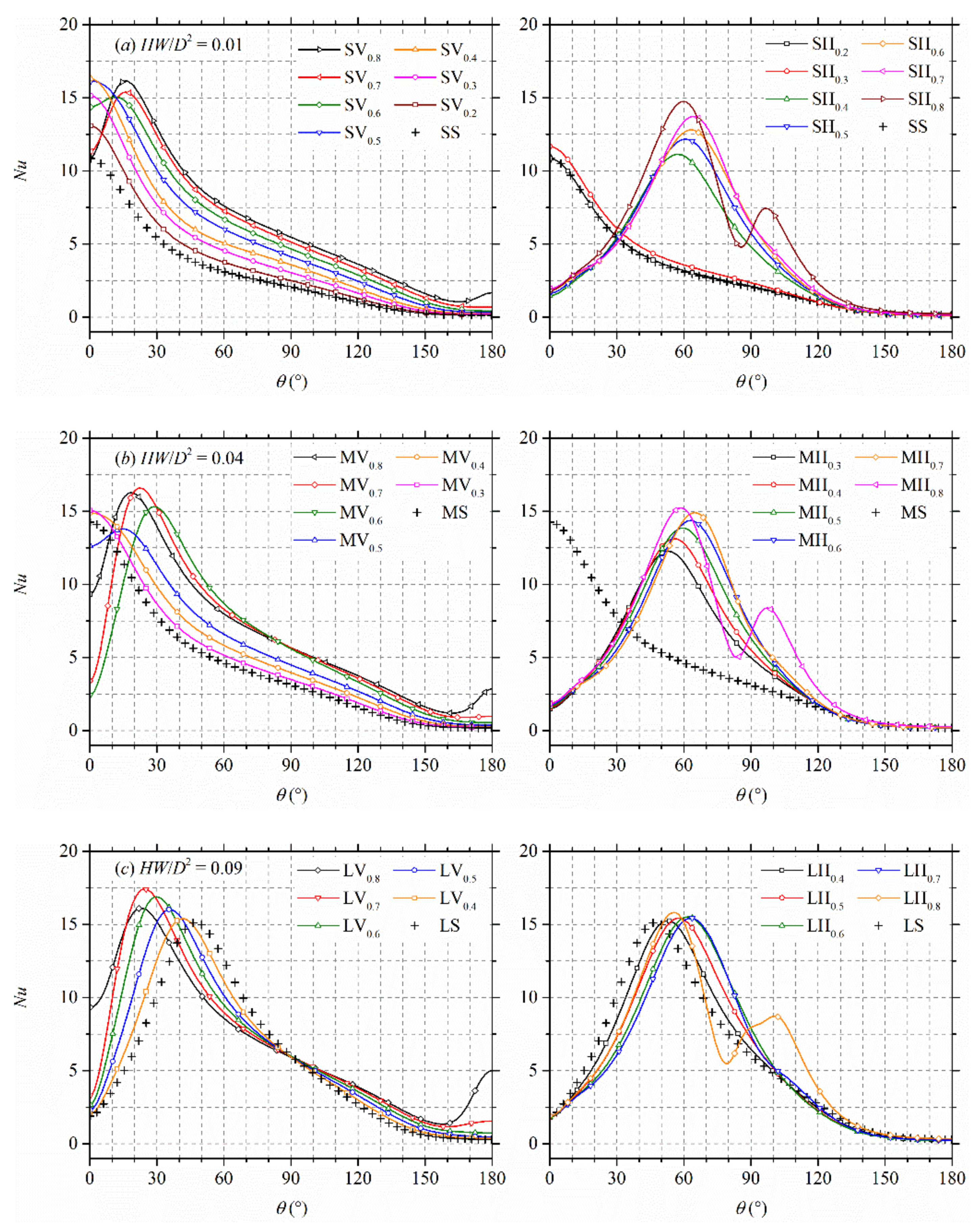
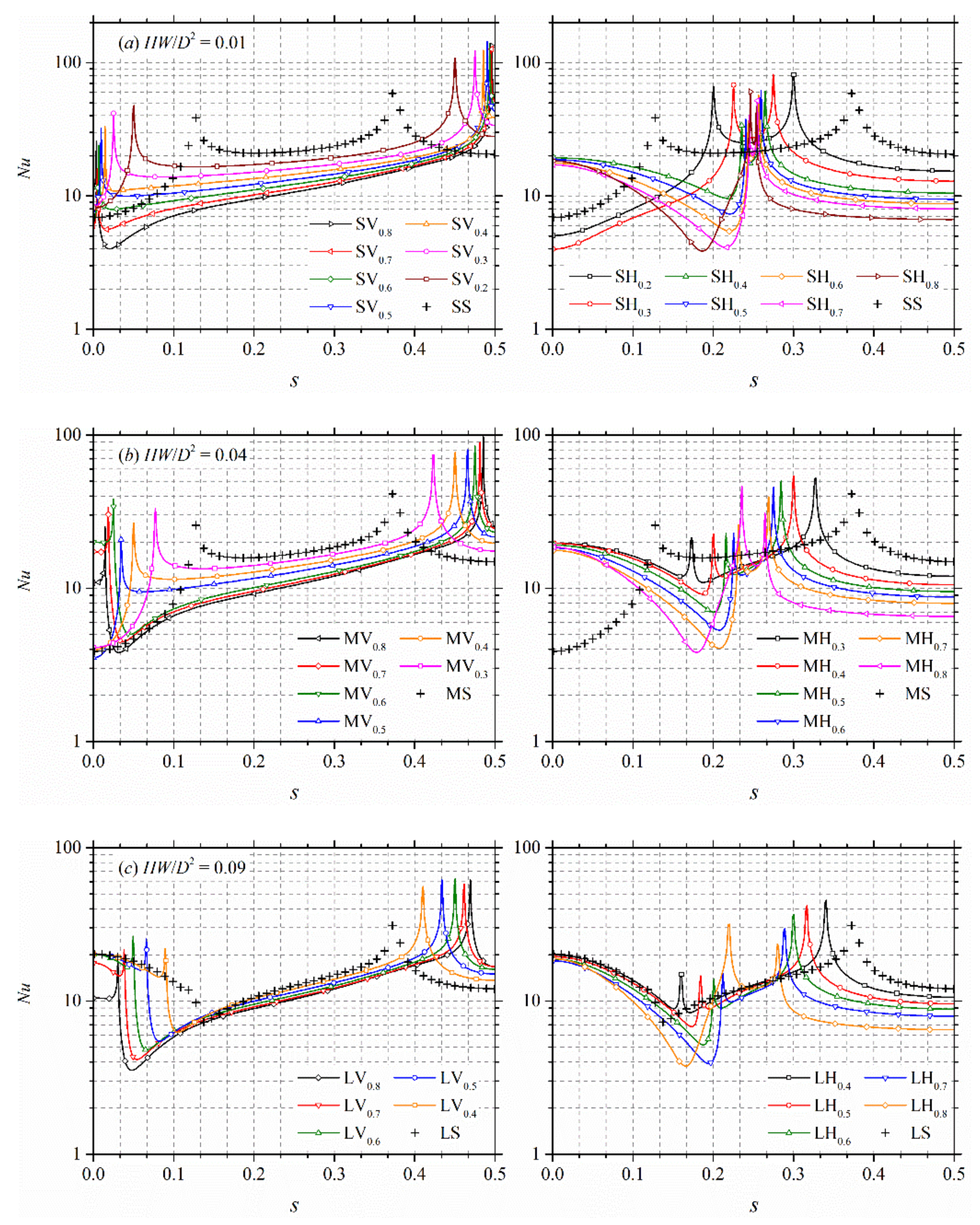
3.3. Local Heat Transfer
3.4. Synergy Principle Analysis
4. Conclusions
- (1)
- The vertically placed plate produces significant convection heat transfer with a higher mean Nusselt number than the horizontal plate. However, the overall heat transfer rate does not vary much with the width of the plate for the horizontally placed plate cases.
- (2)
- For the vertically placed plate, there is always one primary vortex to each side of the plate, and one secondary vortex may form above the plate as the width increases, especially for plates with larger cross-section areas. For the horizontally placed plate with a large width, the primary vortex can be separated by the end of the plate into two, and a secondary vortex forms above the plate.
- (3)
- The magnitude of the local heat transfer rate on the enclosure surface is higher as the circulating flow impinges on the surface, and it is normally maximum at the circumferential position of the thermal plume. The secondary vortex above the plate actually reduces the local heat transfer rate at the top of the enclosure.
- (4)
- A field synergy analysis revealed that the contribution of fluid circulation to the convection heat transfer mainly appears at the center of the vortices, at the boundary of neighboring vortices where the thermal plume forms, and above the plate.
Author Contributions
Funding
Conflicts of Interest
References
- Alteç, Z.; Kurtul, Ö. Natural convection in tilted rectangular enclosures with a vertically situated hot plate inside. Appl. Therm. Eng. 2007, 27, 1832–1840. [Google Scholar] [CrossRef]
- Wang, X.; Shi, D.; Li, D. Natural convective flow in an inclined lid-driven enclosure with a heated thin plate in the middle. Int. J. Heat Mass Trans. 2012, 55, 8073–8087. [Google Scholar] [CrossRef]
- Öztop, H.F.; Dagtekin, I.; Bahloul, A. Comparison of position of a heated thin plate located in a cavity for natural convection. Int. Commun. Heat Mass Trans. 2004, 31, 121–132. [Google Scholar] [CrossRef]
- Tasnim, S.H.; Collins, M.R. Suppressing natural convection in a differentially heated square cavity with an arc shaped baffle. Int. Commun. Heat Mass Trans. 2005, 32, 94–106. [Google Scholar] [CrossRef]
- Wang, Q.W.; Yang, M.; Tao, W.Q. Natural convection in a square enclosure with an internal isolated vertical plate. Warme Stoffubertrag 1994, 29, 161–169. [Google Scholar] [CrossRef]
- Abdul Hakeem, A.K.; Saravanan, S.; Kandaswamy, P. Buoyancy convection in a square cavity with mutually orthogonal heat generating baffles. Int. J. Heat Fluid Flow 2008, 29, 1164–1173. [Google Scholar] [CrossRef]
- Kandaswamy, P.; Abdul Hakeem, A.K.; Saravanan, S. Internal natural convection driven by an orthogonal pair of differentially heated plates. Comput. Fluids 2015, 111, 179–186. [Google Scholar] [CrossRef]
- Singh, P.; Liburdy, J.A. Effect of plate inclination on natural convection from a plate to its cylindrical enclosure. ASME J. Heat Transf. 1986, 108, 770–775. [Google Scholar] [CrossRef]
- Zhang, W.; Wei, Y.; Chen, X.; Dou, H.-S.; Zhu, Z. Partitioning effect on natural convection in a circular enclosure with an asymmetrically placed inclined plate. Int. Commun. Heat Mass Trans. 2018, 90, 11–22. [Google Scholar] [CrossRef]
- Dagtekin, I.; Öztop, H.F. Natural convection heat transfer by heated partitions within enclosure. Int. Commun. Heat Mass Trans. 2001, 28, 823–834. [Google Scholar] [CrossRef]
- Nag, A.; Sarkar, A.; Sastri, V.M.K. Natural convection in a differentially heated square cavity with a horizontal partition plate on the hot wall. Comput. Method Appl. Mech. Eng. 1993, 110, 143–156. [Google Scholar] [CrossRef]
- Tasnim, S.H.; Collins, M.R. Numerical analysis of heat transfer in a square cavity with a baffle on the hot wall. Int. Commun. Heat Mass Trans. 2004, 31, 639–650. [Google Scholar] [CrossRef]
- Sun, C.; Yu, B.; Öztop, H.F.; Wang, Y.; Wei, J. Control of mixed convection in lid-driven enclosures using conductive triangular fins. Int. J. Heat Mass Trans. 2011, 54, 894–909. [Google Scholar] [CrossRef]
- Wei, Y.; Yang, H.; Dou, H.-S.; Lin, Z.; Wang, Z.; Qian, Y. A novel two-dimensional coupled lattice Boltzmann model for thermal incompressible flows. Appl. Math. Comput. 2018, 339, 556–567. [Google Scholar] [CrossRef]
- Lun, Y.X.; Lin, L.M.; Zhu, Z.C.; Wei, Y.K. Effects of vortex structure on performance characteristics of a multiblade fan with inclined tongue, P.I. Mech. Eng. Part A 2019, 233, 1007–1021. [Google Scholar] [CrossRef]
- Yang, H.; Yu, P.; Xu, J.; Ying, C.; Cao, W.; Wang, Y.; Zhu, Z.; Wei, Y. Experimental investigations on the performance and noise characteristics of a forward-curved fan with the stepped tongue. Meas. Control 2019, in press. [Google Scholar] [CrossRef] [Green Version]
- Tao, J.; Lin, Z.; Ma, C.; Ye, J.; Zhu, Z.; Li, Y.; Mao, W. An experimental and numerical study of regulating performance and flow loss in a V-port ball valve. J. Fluids Eng. 2020, 142, 021207. [Google Scholar] [CrossRef]
- Wang, Y.; Chen, J.; Zhang, W. Natural convection in a circular enclosure with an internal cylinder of regular polygon geometry. AIP Adv. 2019, 9, 065023. [Google Scholar] [CrossRef] [Green Version]
- Zhang, W.; Wei, Y.; Dou, H.-S.; Zhu, Z. Transient behaviors of mixed convection in a square enclosure with an inner impulsively rotating circular cylinder. Int. Commun. Heat Mass Trans. 2018, 98, 143–154. [Google Scholar] [CrossRef]
- Yang, H.; Zhang, W.; Zhu, Z. Unsteady mixed convection in a square enclosure with an inner cylinder rotating in a bi-directional and time-periodic mode. Int. J. Heat Mass Trans. 2019, 136, 563–580. [Google Scholar] [CrossRef]
- Zhang, W.; Chen, X.; Yang, H.; Liang, H.; Wei, Y. Forced convection for flow across two tandem cylinders with rounded corners in a channel. Int. J. Heat Mass Trans. 2019, 130, 1053–1069. [Google Scholar] [CrossRef]
- Zhang, W.; Yang, H.; Dou, H.-S.; Zhu, Z. Forced convection of flow past two tandem rectangular cylinders in a channel. Numer. Heat Tr. Part A 2017, 72, 89–106. [Google Scholar] [CrossRef]
- Zhang, W.; Li, X.; Zhu, Z. Quantification of wake unsteadiness for low-Re flow across two staggered cylinders, P.I. Mech. Eng. Part C 2019, 233, 6892–6909. [Google Scholar] [CrossRef]
- Zhang, W.; Dou, H.-S.; Zhu, Z.; Li, Y. Unsteady characteristics of low-Re flow past two tandem cylinders. Theor. Comput. Fluid Dyn. 2018, 32, 475–493. [Google Scholar] [CrossRef]
- Zhang, W.; Samtaney, R. Effect of corner radius in stabilizing the low-Re flow past a cylinder. J. Fluids Eng. 2017, 139, 121202. [Google Scholar] [CrossRef]
- Zhang, W.; Yang, H.; Dou, H.-S.; Zhu, Z. Flow unsteadiness and stability characteristics of low-Re flow past an inclined triangular cylinder. J. Fluids Eng. 2017, 139, 121203. [Google Scholar] [CrossRef]
- Kuehn, T.H.; Goldstein, R.J. An experimental and theoretical study of natural convection in the annulus between horizontal concentric cylinders. J. Fluid Mech. 1976, 74, 695–719. [Google Scholar] [CrossRef]
- Siddique, W.; El-Gabry, L.; Shevchuk, I.V.; Hushmandi, N.B.; Fransson, T.H. Flow structure, heat transfer and pressure drop in varying aspect ratio two-pass rectangular smooth channels. Heat Mass Transf. 2012, 48, 735–748. [Google Scholar] [CrossRef]
- Siddique, W.; Shevchuk, I.V.; El-Gabry, L.; Hushmandi, N.B.; Fransson, T.H. On flow structure, heat transfer and pressure drop in varying aspect ratio two-pass rectangular channel with ribs at 45°. Heat Mass Transf. 2013, 49, 679–694. [Google Scholar] [CrossRef]
- Guo, Z.Y.; Tao, W.Q.; Shah, R.K. The field synergy (coordination) principle and its applications in enhancing single phase convective heat transfer. Int. J. Heat Mass Transf. 2005, 48, 1797–1807. [Google Scholar] [CrossRef]


| Notation | H·W/D2 | Remark |
|---|---|---|
| SV | 0.01 | H > W and H/D = 0.2 (0.1) 0.8 |
| SH | 0.01 | H < W and W/D = 0.2 (0.1) 0.8 |
| SS | 0.01 | H/D = W/D = 0.1 |
| MV | 0.04 | H > W and H/D = 0.3 (0.1) 0.8 |
| MH | 0.04 | H < W and W/D = 0.3 (0.1) 0.8 |
| MS | 0.04 | H/D = W/D = 0.2 |
| LV | 0.09 | H > W and H/D = 0.4 (0.1) 0.8 |
| LH | 0.09 | H < W and W/D = 0.4 (0.1) 0.8 |
| LS | 0.09 | H/D = W/D = 0.3 |
| Source | Mesh | keq,i | keq,o |
|---|---|---|---|
| Kuehn and Goldstein | 16 × 19 | 3.024 | 2.973 |
| Present | 128 × 64 | 2.972 | 2.981 |
| 256 × 128 | 2.961 | 2.967 | |
| 512 × 256 | 2.958 | 2.962 |
| Resolution | H/D = W/D = 0.2 | H/D = 0.8 | W/D = 0.8 |
|---|---|---|---|
| 256 × 256 | 3.965 | 6.574 | 5.134 |
| 512 × 256 | 4.102 | 6.699 | 5.367 |
| 512 × 512 | 4.125 | 6.705 | 5.379 |
© 2019 by the authors. Licensee MDPI, Basel, Switzerland. This article is an open access article distributed under the terms and conditions of the Creative Commons Attribution (CC BY) license (http://creativecommons.org/licenses/by/4.0/).
Share and Cite
Wang, A.; Ying, C.; Wang, Y.; Yang, L.; Ying, Y.; Zhai, L.; Zhang, W. Effect of Orientation and Aspect Ratio of an Internal Flat Plate on Natural Convection in a Circular Enclosure. Processes 2019, 7, 905. https://doi.org/10.3390/pr7120905
Wang A, Ying C, Wang Y, Yang L, Ying Y, Zhai L, Zhang W. Effect of Orientation and Aspect Ratio of an Internal Flat Plate on Natural Convection in a Circular Enclosure. Processes. 2019; 7(12):905. https://doi.org/10.3390/pr7120905
Chicago/Turabian StyleWang, Anjie, Cunlie Ying, Yingdong Wang, Lijun Yang, Yunjian Ying, Lulu Zhai, and Wei Zhang. 2019. "Effect of Orientation and Aspect Ratio of an Internal Flat Plate on Natural Convection in a Circular Enclosure" Processes 7, no. 12: 905. https://doi.org/10.3390/pr7120905