It is necessary to study the influence of tube diameter on the pre-dryout and dryout regions by establishing a model in order to delay dryout and determine the range of the pipe diameter.
4.1. Establishment of a CO2 Double-Pipe Evaporator Model
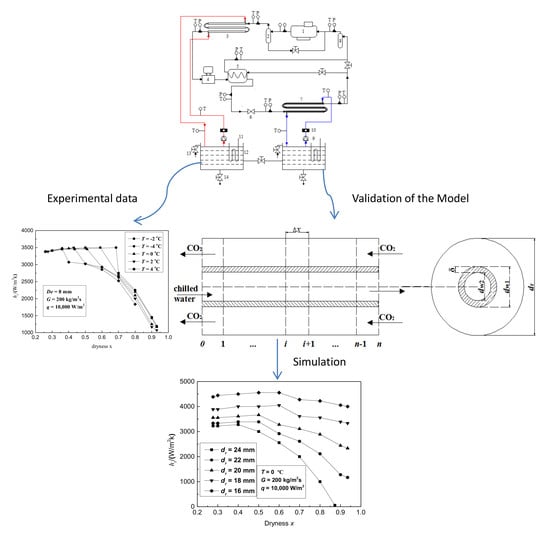
The steady-state distributed-parameter method was used to establish the CO
2 double-pipe evaporator. As shown in
Figure 8, CO
2 and chilled water flowed outside and inside the tube, respectively. The evaporator was divided into
n controlled volume elements along the pipe length, and each part included CO
2 fluid, chilled water, and the pipe wall. For the governing equations of the various parts in the micro-element, the flow of fluid in the inner and outer tubes is regarded as one-dimensional flow [
26]. The changes in fluid conductivity, fluid density, and specific heat as compared to those of CO
2 are negligible when the oil concentration is small [
27]. In addition, as long as a separate liquid CO
2 phase exists, the saturated temperature of the CO
2‒oil mixture is assumed to be equivalent to that of pure CO
2 and the properties of the CO
2‒oil mixture are the same as those of pure CO
2 [
27]. The aim of this simulation is to meet the requirement that the length to diameter ratio of the pipeline be greater than 70, that is
L/d > 70, and thus the inlet effect is not required in determining the heat transfer characteristics of the fully developed fluid [
28,
29]. The steady-state distributed-parameter model was based on the following assumptions:
- (1)
The flow of fluid in the inner and outer tubes was regarded as one-dimensional flow [
26].
- (2)
The outer wall was considered to be adiabatic without considering leakage heat loss.
- (3)
The loss of water-side pressure drop in the evaporator and the momentum equation were not considered.
- (4)
When the refrigerants underwent phase transition, the two phases of the fluid were in a state of thermal equilibrium.
- (5)
The effect of the lubricating oil and other substances on all heat transfer processes was not considered [
27].
For each microelement, the heat absorption on the refrigerant side, the heat release on the chilled water side, and the total heat transfer of the evaporator were the same. The heat transfer temperature difference in the microelement was calculated by the logarithmic mean temperature difference method. The heat transfer characteristics are calculated with Equations (4)–(11) according to thermodynamics and Li’s research [
24].
The refrigerant-side energy is calculated by
The energy equation of the chilled water-side is calculated by
Total heat transfer in evaporator is calculated by
The energy conservation equation of each part is calculated by
The total heat transfer coefficient equation is calculated by
Logarithmic mean temperature difference is expressed, as follows:
The water-side heat transfer coefficient is calculated as follows [
25]:
The correlation form established by Yoon [
30] is used for the calculation of the CO
2-side heat transfer coefficient since the equivalent diameter of the model established in this paper belongs to the range of conventional pipe diameters. The heat transfer coefficient of pre-dryout is expressed, as follows:
The heat transfer coefficient of post-dryout is expressed, as follows:
The corresponding pipe lengths in the two regions were recorded as
L1 and
L2. The mass quality corresponding to dryout (
xcr) is expressed, as follows [
29]:
Bo is the boiling number.
Bd is the Bond number, which is calculated, as follows [
29]:
De is the hydraulic diameter.
L1 and
L2 are calculated, as follows:
Acr is the heat exchange area when the mass quality is
xcr. L is the total tube length, m. The parameter
is defined, as follows:
This parameter indicates the proportion of the dryout stage to the entire heat transfer stage, where a larger value of is desirable.
This model utilized the Matlab package for programming and calculation. The input was divided into three categories: the structural parameters of the evaporator, such as pipe length and diameter; the refrigerant import and export parameters, such as mass flux, evaporation temperature, and pressure; and, the import and export parameters of chilled water, such as flow rate, pressure, and temperature. First, the outlet temperature of chilled water was assumed to calculate the inlet temperature of chilled water, until the difference between the inlet temperature and the given temperature was between −5% and 5%.
Figure 9 shows a flowchart of the simulation.
4.2. Validation of the Model
The simulation values of
hr and pressure were compared with the experimental results in order to verify the accuracy of the model, as shown in
Figure 10. The RE is calculated, as follows:
Figure 10a shows the effects of the chilled water flow rate on the heat transfer. The heat transfer coefficient was found to proportionally increase with the increase in the chilled water flow rate. As can be seen from
Figure 10a, the simulation value is slightly higher than the experimental value. This was attributed to variations in the experimental conditions. The temperature continued to decrease although there was an electric heating wire in the chilled water tank to maintain the constant temperature of the chilled water, which resulted in a decrease in the heat transfer temperature difference, resulting in decreased heat transfer. With the increase in the evaporation temperature, both the simulation value and the experimental value of the average heat transfer coefficient exhibited lower fluctuations, as shown in
Figure 10b. When the evaporation temperature is −1 °C, RE showed a minimum value of 4.41%. When the evaporation temperature was 1 °C, RE showed a maximum value of 5.94% with a 5.21% mean value.
Figure 10c shows the effects of the chilled water inlet temperature on the CO
2 pressure drop. The pressure drop was found to increase proportionally with the increase in the chilled water inlet temperature. When the chilled water inlet temperature was 12 °C, RE has a maximum value of 4.57% and a mean of 3.78%.
This model is used to simulate and analyze the performance of a double-pipe evaporator designed for CO2 transcritical systems since the overall trend of experimental and simulated values is consistent.


