Abstract
Taking the open circuit hydraulic pump-controlled forging press system as the research object, according to the problems of pressure-relief impact of this system, the pressure-relief rules, mathematic models of the energy release rules, and the flow release rules were established, and the pressure-relief performance in different stages of each pressure-relief curve was analyzed. Based on the different requirements of the pressure gradient decrease, the combined pressure-relief curve (CPRC) was proposed to realize variable-pump eccentric magnitude planning. An experimental study on the pressure-relief process with CPRC was carried out. The results show that the pressure fluctuation of the pressure-relief pipe was reduced and the suppression effect of pressure-relief impact was better than that of the single regular pressure-relief curve. When the initial pressures were 10 MPa and 15 MPa, the pressure impact of the pressure-relief tube decreased by 45.45% and 37.5%, respectively, which realized the smooth pressure relief of the main cylinder.
1. Introduction
The forging hydraulic press is a key piece of equipment in heavy machinery and plays a pivotal role in the machinery manufacturing industry. The transmission forms of the forging hydraulic press system are mainly divided into two types: valve-controlled and pump-controlled. Due to the low cost, easy maintenance, and relatively low oil cleanliness requirements of valve-controlled systems, it has become the mainstream form of forging hydraulic presses. However, with the increasing energy crisis, green forging is getting more and more attention, and pump-controlled technology has become a hot research topic because of its enormous advantages in energy saving [1,2].
The pump-controlled system is mostly a closed circuit system, mainly used in engineering machinery such as vibratory rollers, cement mixers, and asphalt pavers [3,4]. Generally, the closed circuit pump-controlled cylinder system can be divided into the Closed Circuit Pump-controlled Symmetrical Cylinder Systems (CCPSCS), such as ship steering system [5], and Closed Circuit Pump-controlled Asymmetric Cylinder Systems (CCPACS). The CCPACS adopts a bidirectional variable mechanism to realize the reversing of the inlet and outlet, avoiding throttling loss and overflow loss, and has the advantages of economy, energy saving, and low installed power [6,7,8]. Zimmerman, J. [9] applied CCPACS to the forging hydraulic press, and the system had a good dynamic response, good control characteristics, a stable operation, and a fast forging speed. However, the CCPACS has the characteristic of flow imbalance, so a large flow charge pump must be added, and it also has the problems of low power recovery rate and large system fever, etc. [10].
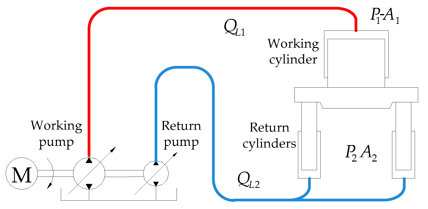
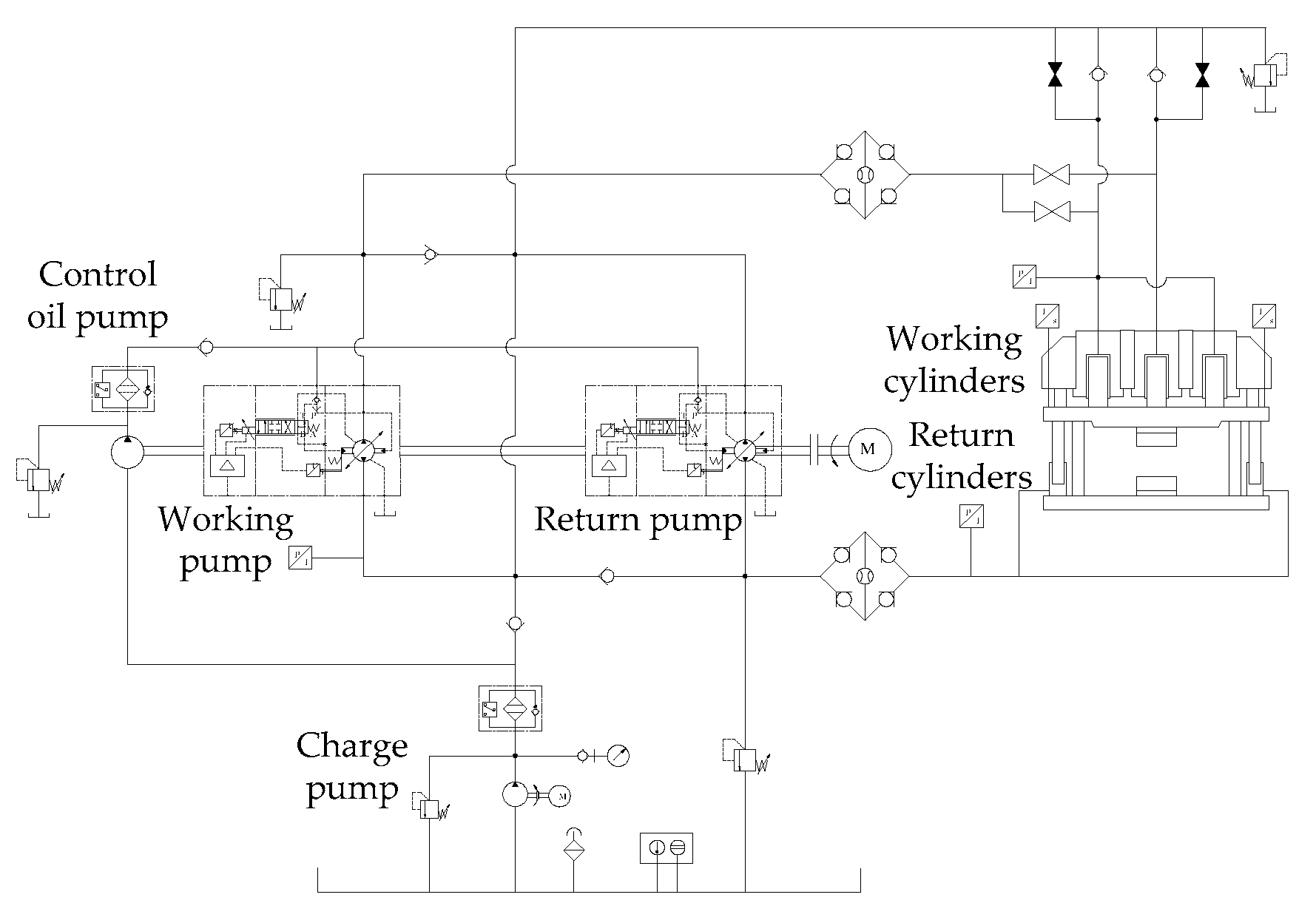
We propose an Open Circuit Pump-controlled Asymmetric Cylinder System (OCPACS) to address the above issues, and we apply it to the forging hydraulic press system. The principle of the Open Circuit Pump-controlled Forging Hydraulic System (OCPFHS) is shown in Figure 1. The OCPFHS uses two pumps to control the two cylinder chambers independently, which solves the two-chamber flow asymmetry problem. At the same time, the large flow-charge pump with low pressure oil supplement is omitted, thus improving the energy utilization efficiency. In previous work, we studied the control characteristics [11], energy consumption characteristics [12], control coupling characteristics [13,14], accumulator fast-forging circuit-control characteristics and their influencing factors [15], and long pipeline characteristics [16] of the OCPFHS.
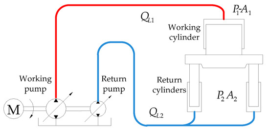
Figure 1.
The Open Circuit Pump-controlled Forging Hydraulic System (OCPFHS) diagram.
When the hydraulic press system completes the reduction process, it is necessary to quickly release the high pressure oil in the working cylinder before the return stroke, which is called the pressure-relief process [17,18]. If the pressure-relief process is not handled properly, it will cause impact and vibration of the pipeline and frame. The pressure-relief impact control of hydraulic presses has always been a subject of great concern in academia and the engineering technology field.
Consensus on the formation and development mechanism of pressure relief has not yet been reached. At present, researches mainly focus on the valve-controlled hydraulic press system, including analyzing the transmission rule of the pressure wave in the pipeline [19,20], proposing the active compensation method for the pressure-impact prediction of the directional valve [21,22], using the electro-hydraulic proportional cartridge valve as the pressure-relief valve [23], and designing an energy sinusoidal pressure-relief curve [24]. However, research on the pressure-relief process of pump-controlled hydraulic presses has rarely been reported.
Referring to the design method of the relief curve of the electro-hydraulic proportional cartridge valve to solve these problems, this paper studies the pressure-relief impact control of the OCPFHS, puts forward the combined pressure-relief curve (CPRC), and deduces the mathematical model of CPRC. The simulation and experimental results verify the pressure-relief impact-suppression effect of CPRC, which proves the effectiveness of this pressure-relief method.
2. Pressure-Relief Mechanism
2.1. Energy Storage Characteristics Analysis
After the hydraulic press system completes the working process, the hydraulic system stores a lot of high pressure oil. While the mechanical structure of the main body frame, pipelines, and working cylinder are deformed because of the high pressure, the elastic potential energy is stored. All the energy needs to be released through the oil in the working cylinder and pipelines during the pressure-relief process [25].
2.1.1. Working Cylinder Oil Compression Energy Storage
According to the oil compression equation, the working cylinder oil compression is [26],
where V0 is the working cylinder oil volume before pressure relief, ΔV is the working cylinder oil compression volume, E is the effective fluid bulk modulus, ΔP is the working cylinder pressure variation, and P is the working cylinder pressure.
Since P << E, so E − P ≈ E, and the working cylinder oil compression is,
Regardless of the elastic potential energy generated by the expansion of the working cylinder, the working cylinder fluid compression energy is,
where ΔW1 is the working cylinder oil compression energy variation.
According to Equations (2) and (3),
The integral of Equation (4) can be obtained,
Therefore, the working cylinder fluid compression energy storage is as follows,
2.1.2. Frame Elastic-Deformation Energy Storage
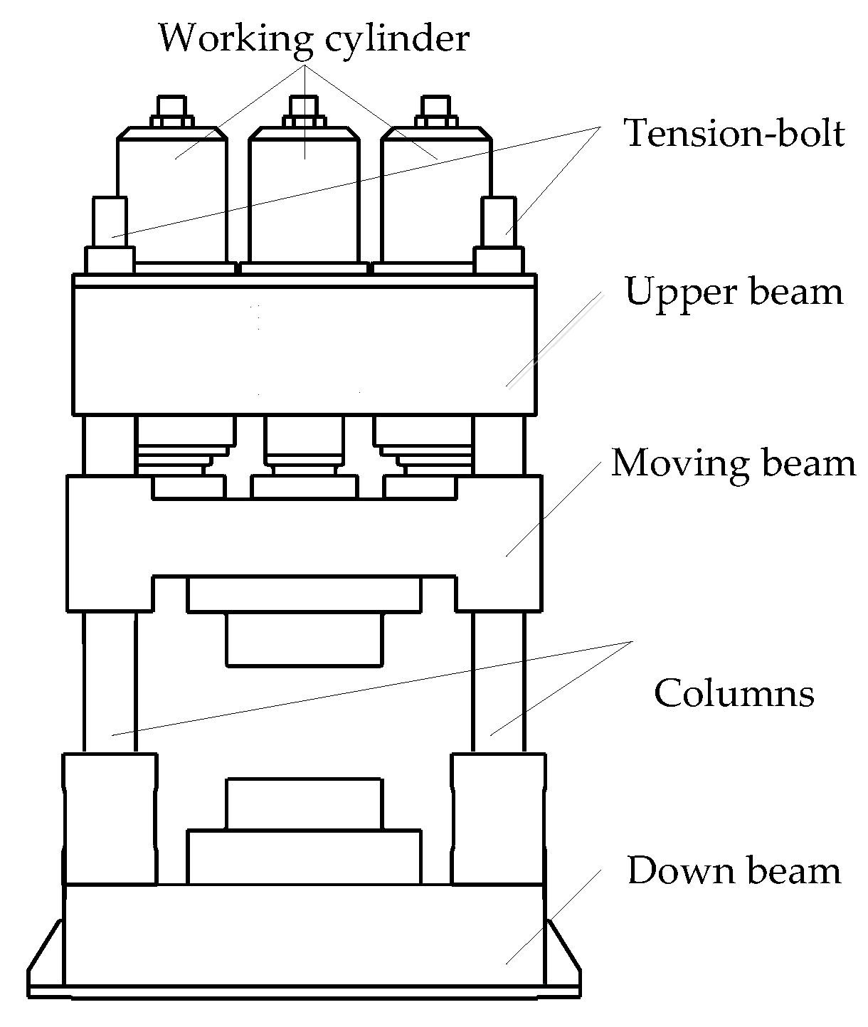
The frame diagram of the hydraulic press is shown in Figure 2. Before pressure relief, the hydraulic press frame elastic-deformation energy storage is mainly composed of the deformation energy storage of the upper beam, the moving beam, the columns, and tension-bolt. Since the upper beam and the moving beam all have greater quality and strength, the deformation is very small. However, the deformation of the columns and tension-bolt are larger, and a higher energy is stored.
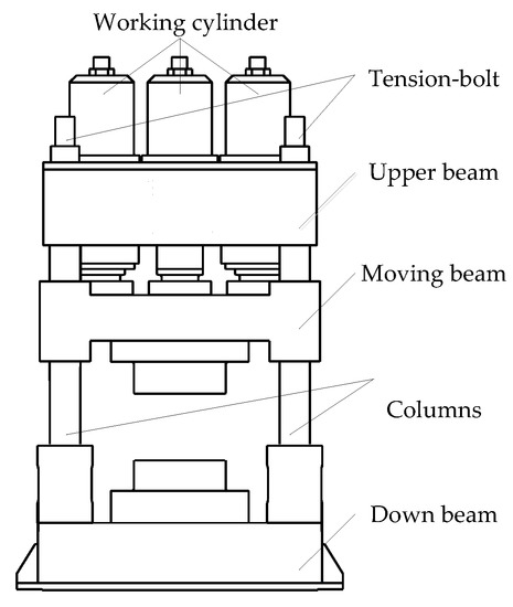
Figure 2.
The frame diagram of the hydraulic press.
The deformation of the columns and the tension-bolt is as follows,
where Lz is the length of the columns and tension-bolt, Ez is the effective fluid bulk modulus of the columns and tension-bolt, Az is the equivalent cross-sectional area of the columns and tension-bolt, and Fz is the load of a single column and tension-bolt.
The load of a single column and tension-bolt is as follows,
where D1 is the inside diameter of the working cylinder, n1 is the number of working cylinders, and n2 is the number of columns and tension-bolts.
Energy storage of columns and tension-bolt is,
According to Equations (7) and (9),
According to Equations (7), (8) and (10),
Assuming that , then the elastic-deformation energy storage of the columns and tension-bolt is,
Therefore, before pressure relief, the total energy storage of the hydraulic press system is mainly the compression energy of the cylinder oil and the elastic-deformation energy of the frame. The total energy storage of the system is as follows,
2.2. Energy Storage Characteristics Analysis
2.2.1. Oil Compression Energy Storage Characteristics
Assuming that the amount of oil compression changes from the highest pressure to zero, then the compression energy stored in the working cylinder before the pressure relief is obtained by Equations (2) and (6),
The effective fluid bulk modulus of oil is determined by the pressure, temperature, gas content, etc. Since the pressure-relief time is very short, assuming that the temperature and gas content keep invariant, then the rule of effective fluid bulk modulus variation with pressure [27] is,
It is known from Equations (14) and (15) that when the working cylinder pressure increases, the rule of the oil compression energy storage of the working cylinder is consistent with the rule of the effective fluid bulk modulus variation with pressure, and the energy gradient gradually becomes smaller. Therefore, with the increase of the working cylinder pressure, the change tendency of the compression energy storage of the working cylinder is initially fast and then slow.
2.2.2. Frame Elastic-Deformation Energy Storage Characteristics
The frame elastic-deformation energy storage is mainly composed of the elastic-deformation energy storage of the column and tension-bolt. According to the Equation (12), with the increase of the working cylinder pressure, the change tendency of the frame elastic-deformation energy storage is initially slow and then fast.
2.2.3. Pressure Energy Storage Characteristics of OCPFHS
Taking the 0.6 MN forging press experimental platform as the research object, the energy storage state of the system before the pressure relief was analyzed. The system parameters under a certain condition are shown in Table 1.

Table 1.
Energy storage state parameters of the 0.6 MN forging press test-bed before the pressure relief under a certain condition.
Taking these condition parameters into Equations (6) and (12), the oil compression energy storage and the frame elastic-deformation energy storage of the 0.6 MN forging press are, respectively, as follows, W1 = 175.5 J and W2 = 27.7 J.
That is, the frame elastic-deformation energy storage is about 13.6% of the total energy storage. Therefore, the oil compression energy storage before the pressure relief is the main factor determining the variation of the energy storage.
2.2.4. Pressure-Relief Impact Characteristics
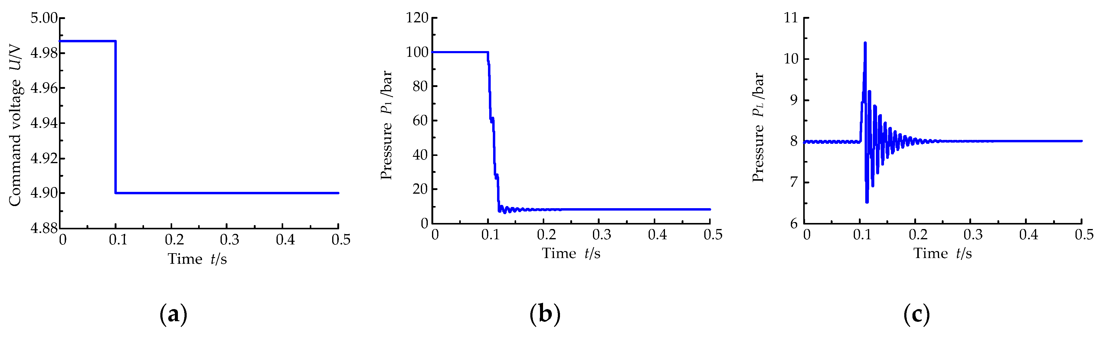
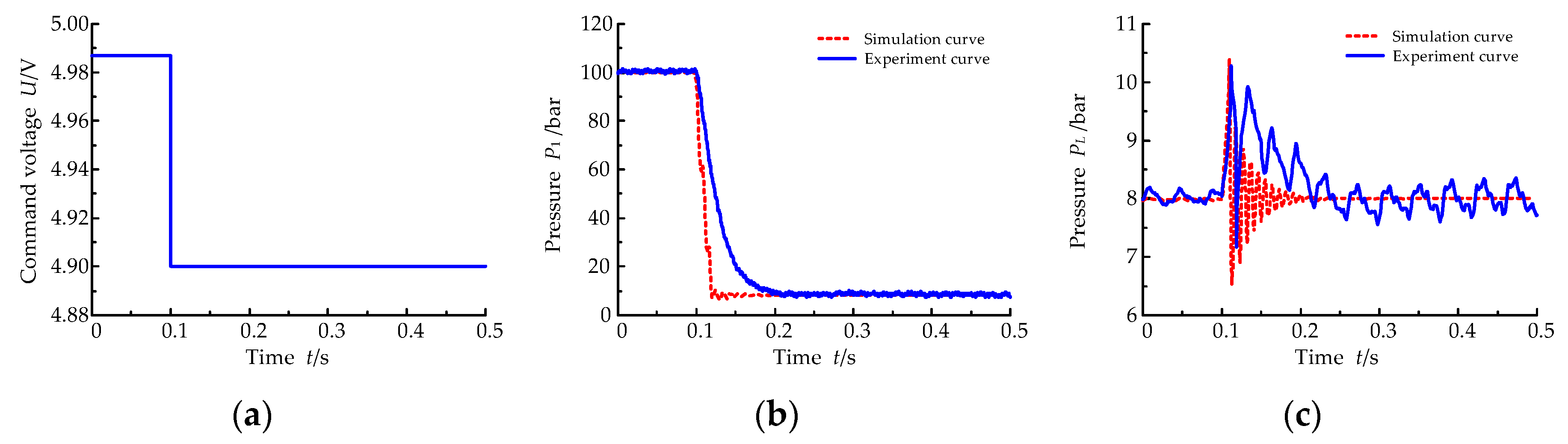
Using the mathematical model deduced in reference [12] and MATLAB/Simulink simulation platform (MATLAB 2010 a, MathWorks, Natick, MA, USA, 2010) to establish the simulation model of OCPFHS, a step signal was used to relieve the pressure of the OCPFHS, and the variable-pump eccentric magnitude curve, working cylinder pressure curve, and relief pipe (connected with the low pressure port of the variable pump, supplied with 8 bar charge pressure in the actual system) pressure curve were obtained under the initial pressure of 100 bar, as shown in Figure 3. In the simulation, the 0–0.1 s was the 100 bar packing stage, and the 0.1–0.5 s was the pressure-relief process. In this paper, the variable-pump eccentric magnitude was characterized by the given voltage variation, and the command voltage of the variable pump was 0–10 V, corresponding to the eccentric magnitude of −5–5mm.
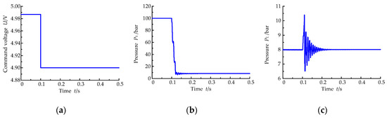
Figure 3.
The simulation curve under the step pressure-relief rule. (a) Eccentric magnitude; (b) Working cylinder pressure; (c) Relief-pipe pressure.
As shown in Figure 3, when the OCPFHS adopts step pressure relief, the working cylinder pressure decreases rapidly, and realizes pressure relief in a short time. However, the working cylinder pressure fluctuates during the descent process, and the peak pressure in the relief pipe is 10.398 bar, which exceeds the steady pressure of 29.97%, indicating that the pressure-relief process produces a strong pressure-relief impact.
In order to avoid the pressure-relief impact and realize the smooth operation of the OCPFHS, it is necessary to select a reasonable pressure-relief curve according to the energy storage variation rule of the system to realize the pressure-relief impact control.
3. Pressure-Relief Curve
One of the main influencing factors of the stability and life of forging hydraulic press is the degree of pressure-relief impact, and the quality of its control directly determines the working characteristics and production efficiency of the equipment. The optimal control should be sought by considering the optimal working characteristics and high production efficiency as the control objectives of pressure relief.
3.1. Mathematical Model of the Pressure-Relief Curve
To solve the problem of pressure-relief impact, a reasonable pressure-relief curve should be selected. By analyzing the mathematical characteristics of different curves, there are two types of curves that can be used as solutions for pressure-relief curves. One is uniform motion with flexible impact characteristics, the other is sinusoidal motion without impact. Using the above two types of flexible motion rules to derive the mathematical model of the relationship between the pressure of the working cylinder, the pressure-relief time and the displacement change of the variable pump, a reasonable pressure-relief curve is obtained to achieve a smooth pressure relief.
The main factors causing pressure-relief impact are the irregular release of energy and the irregular change of flow. According to the above two kinds of flexible motion rules, the working cylinder pressure curves of energy and flow under uniform rules and sinusoidal rules are deduced, respectively, and finally, the given eccentric magnitude curve of the variable pump is obtained [28].
3.1.1. Working Cylinder Pressure-Relief According to the Energy Rule
From the energy point of view, the pressure-relief process is the release process of the working cylinder oil-compression energy and the frame elastic-deformation energy, which needs to consider what kind of relief rule can make the system smoothly reduce from high pressure to low pressure.
Because the pressure-relief process is so short, it is considered that the temperature is constant, the gas content in the oil is unchanged, and no cavitation occurs.
The initial relief pressure of the working cylinder is P0, then its initial energy storage W0 is,
The mathematical model of the pressure-relief characteristic curve according to the energy uniform rule is,
where t is the pressure-relief time and T is the pressure-relief cycle.
According to Equations (13) and (17),
Therefore, the working cylinder pressure varies according to the energy uniform rule,
The derivative of the working cylinder pressure is,
The mathematical model of the pressure-relief characteristic curve according to the energy sinusoidal energy rule is,
According to Equations (13) and (21),
Therefore, the working cylinder pressure varies according to the energy sinusoidal energy rule,
The derivative of the working cylinder pressure is,
3.1.2. Working Cylinder Pressure Relief According to the Flow Rule
The working cylinder pressure-relief process from the flow variation rule mainly considers the impact of the oil-inertia force on the sudden changes in the working cylinder flow.
The mathematical model of the pressure-relief characteristic curve according to the flow uniform rule is,
where Q1 is the system flow when the displacement of the variable pump is changed to the maximum and t1 is the opening time when the displacement of the variable pump is changed to the maximum.
From 0 to t1, the working cylinder oil volume variation is,
The definition of effective fluid bulk modulus is,
According to Equations (26) and (27),
When t = t1, the above equation becomes,
where P1 is the system pressure when the variable-pump displacement is changed to the maximum.
The flow equation of the variable-pump outlet is,
where emax is the maximum variable-pump eccentric magnitude.
According to Equations (29) and (30),
Therefore, when t = t1, the working cylinder pressure is,
According to Equations (30) and (32), when t = t1, the working cylinder flow is,
By the Equations (28) and (33), the working cylinder pressure varies according to the flow uniform rule,
The derivative of the working cylinder pressure is,
The mathematical model of the pressure-relief characteristic curve according to the flow sinusoidal rule is,
From 0 to t1, the working cylinder oil volume variation is,
According to Equations (27) and (37),
When t = t1, the above equation becomes,
According to Equations (30) and (39),
Therefore, when t = t1, the working cylinder pressure is,
According to Equations (30) and (41), when t = t1, the working cylinder flow is,
By the Equations (38) and (42), the working cylinder pressure varies according to the flow uniform rule,
The derivative of the working cylinder pressure is,
3.2. Variable-Pump Eccentric Magnitude Curve during the Pressure-Relief Process
The pressure-variation rule in the pressure-relief process of the OCPFHS is realized by adjusting the variable-pump eccentric magnitude. The mathematical model is used to analyze the pressure variation curve of the working cylinder during the pressure-relief process, and the control signal curve of the variable pump is obtained.
The working cylinder flow continuity equation is,
During the pressure-relief process, the displacement of the working cylinder is zero and the flow continuity equation is,
The variable-pump inlet flow equation is,
According to Equations (46) and (47),
Therefore, the relationship between the variable-pump eccentric magnitude and the system pressure is,
The 0.6 MN forging press system parameters under a certain condition are shown in Table 2.
Table 2.
The system parameters of the 0.6 MN forging press test-bed before the pressure relief under certain condition.
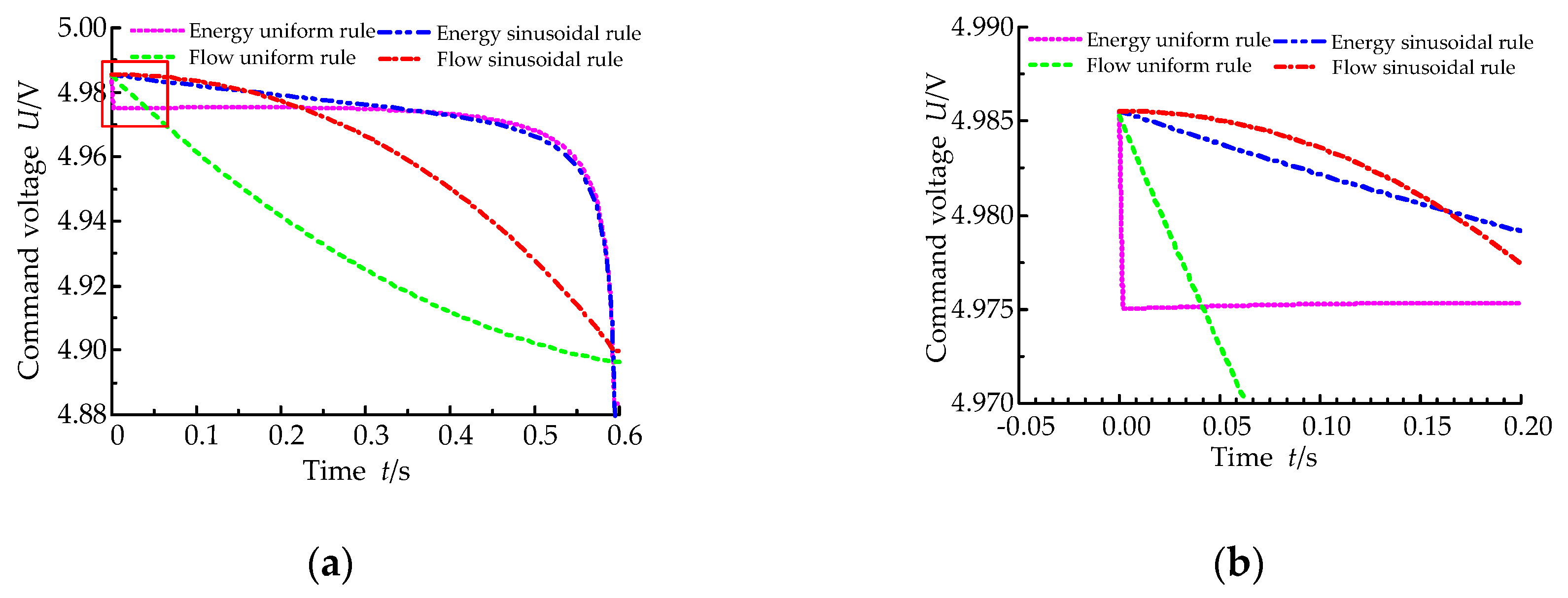
Based on the above analysis, the working pump of the OCPFHS is simulated and the variable-pump eccentric magnitude curve under an initial pressure of 100 bar and a pressure-relief cycle at 0.6 s is obtained, as shown in Figure 4.
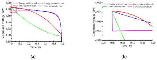
Figure 4.
Simulation curves of variable-pump eccentric magnitude changes under the different pressure-relief rules. (a) Eccentric magnitude curve; (b) Partial magnification.
As shown in Figure 4, when the energy storage before pressure relief is released according to the rules, the variable-pump eccentric magnitude increases continuously. The starting point of pressure relief is not the point where the eccentric magnitude is zero (when the voltage signal is 5 V, the eccentric magnitude is zero), which is due to the existence of the variable-pump leakage, and there must be a certain dynamic balance between the flow and leakage.
When the energy uniform rule and the energy sinusoidal rule are used to relieve the pressure, the variable-pump eccentric magnitude follows the rule of initially slow and then fast, which can better suppress the pressure-relief impact. In first slow process, the variable-pump eccentric magnitude is always a smaller value, resulting in less volume increase due to oil compression and frame elastic deformation, so that the flow is smaller. When the flow uniform rule and the flow sinusoidal rule are used to relieve the pressure, the variable-pump eccentric magnitude increases from zero to the maximum, and follows the rule of initially slow and then fast.
According to the above variation rule of variable-pump eccentric magnitude in the pressure-relief process, the simulation pressure-relief curve of the working cylinder under different pressure-relief rules is obtained, as shown in Figure 5. Figure 5 shows that the pressure relief can be completed within the pressure-relief cycle when the pressure is released according to the rules. According to the energy uniform rule and energy sinusoidal rule, the pressure-relief process follows the rule of initially slow and then fast. During the initial stage of pressure relief, the pressure change is small and the time is longer, meanwhile the pressure gradient in the latter stage is increased. According to the flow uniform rule and the flow sinusoidal rule, the pressure change at the initial stage of pressure relief follows the rule of initially slow and then fast. However, in the process of pressure relief, most of the energy is relieved by a large pressure gradient, which is not conducive to suppressing the impact in the high pressure stage.
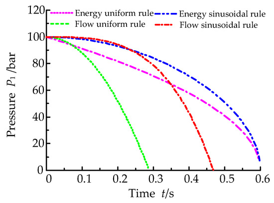
Figure 5.
The simulation curve of working cylinder pressure under the different pressure-relief rules.
4. CPRC
The pressure-relief curve with a single rule can have excellent performance in a certain stage of the pressure-relief process, but it is difficult to meet the requirements of pressure-relief stability and rapidity throughout the pressure-relief process. In order to achieve the above goals, a CPRC can be used to solve the main contradiction at each stage of pressure-relief process.
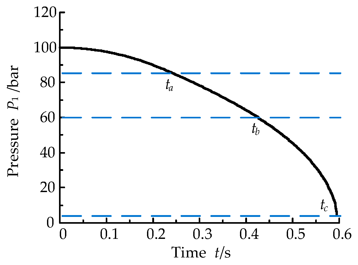
Overall, in the whole cycle of the pressure-relief process, a reasonable distribution of the pressure gradient and a short pressure-relief time are fundamental to achieve pressure-relief impact control. According to the pressure-impact strength, the pressure-relief process can be divided into three stages [28]: The first stage is the high pressure stage where the pressure is about 100%–85% of the initial pressure. This stage may cause the greatest impact and requires a smaller pressure gradient. An energy sinusoidal curve can be used for pressure relief in this stage; The second stage is the medium pressure stage, the pressure is about 85%–60% of the initial pressure, and the pressure gradient can be properly increased during this stage. An energy uniform curve can be used for pressure relief in this stage; The third stage is the low pressure stage, the pressure is about 60% back pressure of the initial pressure, the impact generated during this stage is small and a large pressure gradient can be configured to shorten the pressure-relief cycle. An energy sinusoidal curve can be used in this stage.
The switching point ta of the first and second stages is the time that the pressure drops to 85% of the initial pressure, the switching point tb of the second and third stages is the time that the pressure drops to 60% of the initial pressure, and the end point tc of the third stage is the time that the pressure drops to 8% of the initial pressure (taking an initial pressure of 100 bar and a back pressure of 8 bar as an example), as shown in Figure 6. At the curve-switching point, it is necessary to ensure that the two curves to be switched have the same variable-pump eccentric magnitude. Therefore, each curve needs to adopt an appropriate pressure-relief cycle.
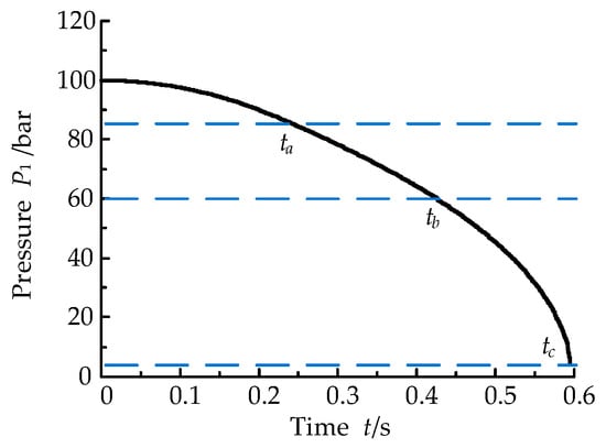
Figure 6.
The switch point schematic diagram of the combined pressure-relief curve (CPRC).
The pressure-relief process is a fast transient process. The control method is based on the pressure-relief curve deduced from the pressure-relief mechanism for open-loop control. It is necessary to calculate the switching point of the piecewise function of the combined pressure-relief curve under the particular pressure-relief cycle and initial pressure condition.
According to the energy sinusoidal curve, the pressure drops to 85% of the initial pressure at,
where ta1 is the time that the pressure drops to 85% of the initial pressure according to the energy sinusoidal curve and T1 is the pressure-relief cycle of the first stage pressure-relief curve.
According to the energy sinusoidal rule and the energy uniform rule, when the pressure drops to 85% of the initial pressure, the equal eccentric magnitude value is,
where ta2 is the time that the pressure drops to 85% of the initial pressure according to the energy uniform curve and T2 is the pressure-relief cycle of the second stage pressure-relief curve.
According to the energy uniform curve, the pressure drops to 85% and 60% of the initial pressure at,
where tb1 is the time that the pressure drops to 60% of the initial pressure according to the energy uniform curve.
According to the energy uniform rule and the energy sinusoidal rule, when the pressure drops to 60% of the initial pressure, the equal eccentric magnitude value is,
where tb2 is the time that the pressure drops to 60% of the initial pressure according to the energy uniform curve and T3 is the pressure-relief cycle of the third stage pressure-relief curve.
According to the energy sinusoidal curve, the pressure drops to 60% of the initial pressure at,
The OCPFHS always maintains a constant back pressure. According to the energy sinusoidal curve of the pressure-relief cycle at T3, the pressure when it drops to the back pressure is,
where tc is the time that the pressure drops to back pressure according to the energy sinusoidal curve and Pb is the back pressure.
Then, the total relief time of CPRC is,
In summary, the pressure equation of CPRC is,
The variable-pump eccentric magnitude equation with CPRC is,
5. Simulation Analysis
5.1. Simulation of CPRC
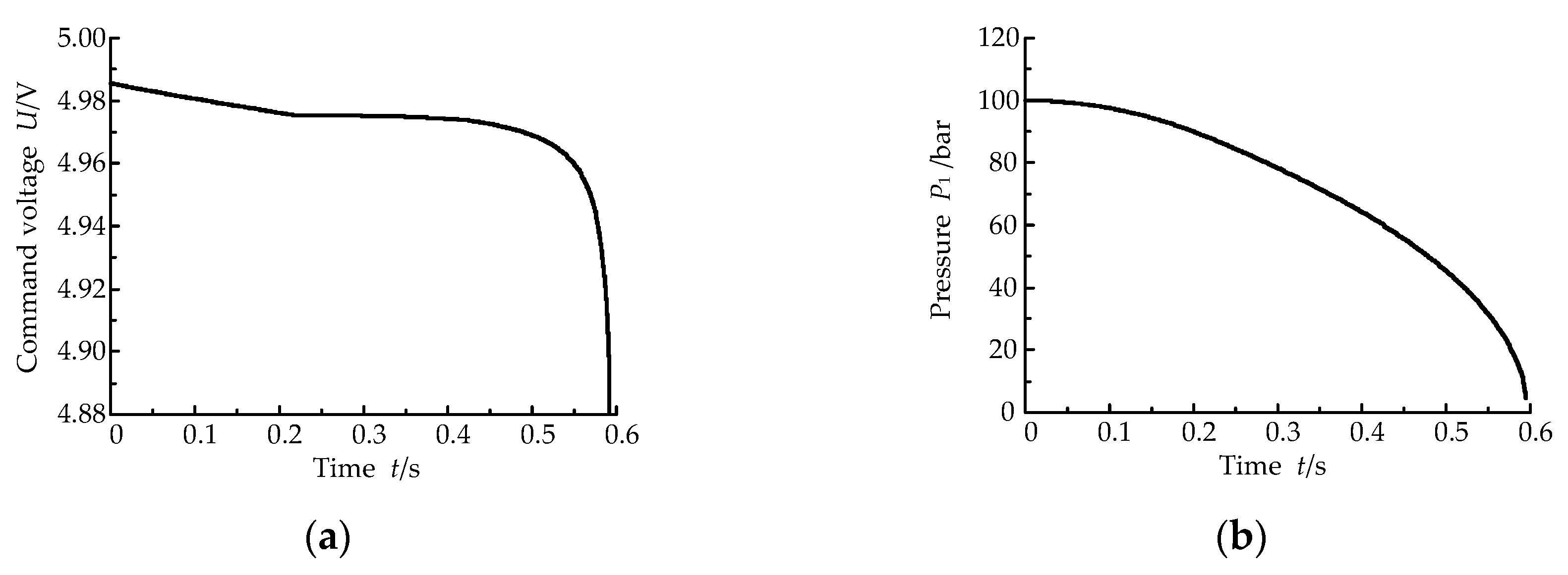
Through the above analysis, taking the 0.6 MN forging press experimental platform as the research object, the OCPFHS with 100 bar initial pressure and a 0.6 s pressure-relief cycle is used to simulate the corresponding variable-pump eccentric magnitude curve and the CPRC curve, as shown in Figure 7.
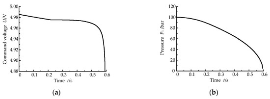
Figure 7.
The simulation curve under the CPRC rule. (a) Eccentric magnitude curve; (b) Calculation CPRC.
Using the above variable-pump eccentric magnitude variation curve, the working cylinder simulation pressure-relief curve and the corresponding variable-pump eccentric magnitude curve under different pressure-relief rules are obtained, as shown in Figure 8.

Figure 8.
The simulation curve under the different pressure-relief rules under initial pressures of 100 bar. (a) Eccentric magnitude curves; (b) Calculation of CPRC.
As shown in Figure 8, the CPRC meets the requirements of pressure-relief stability and rapidity in the pressure-relief process. Compared with the single pressure-relief curve, the partial characteristics are optimized, and the advantages of different curves are taken into account.
5.2. Pressure-Relief Impact Control
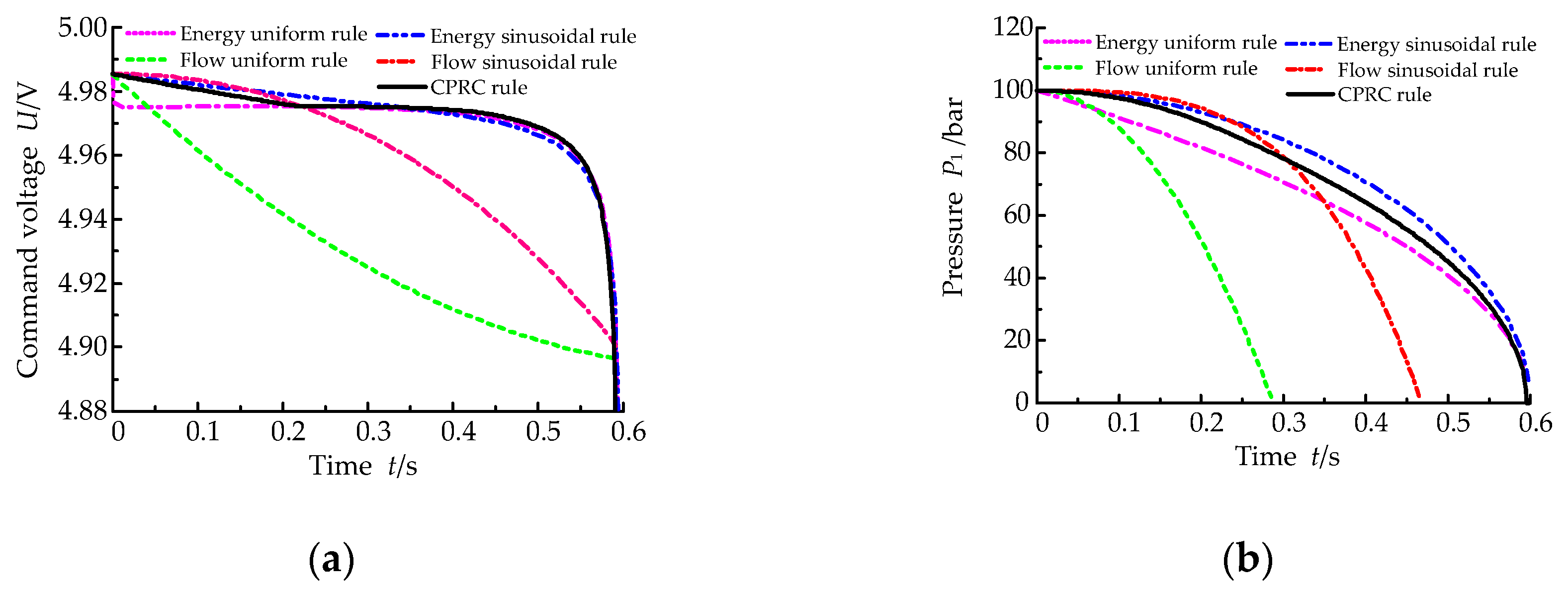
Under the above pressure-relief rules, the initial pressure of 150 bar was used as the research condition to generate the working cylinder simulation pressure-relief curve and the corresponding variable-pump eccentric magnitude curve under different pressure-relief rules, as shown in Figure 9.
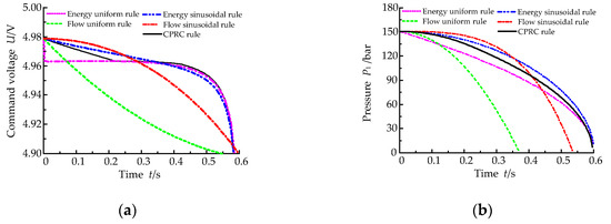
Figure 9.
The simulation curve under the different pressure-relief rules under initial pressures of 150 bar. (a) Eccentric magnitude curve; (b) Pressure-relief curves.
Figure 8 and Figure 9 show that in the pressure-relief initial pressure, when the storage energy of the working cylinder changes in accordance with flow uniform rule, flow sinusoidal rule, energy uniform rule, CPRC rule, and energy sinusoidal rule in turn, the working cylinder pressure-relief time increases, but it is controlled in the 0.6 s pressure-relief cycle. With the same pressure-relief curve and different initial pressures, as the pressure-relief initial pressure increases, the energy stored in the working cylinder and the pipeline increases, resulting in an increased pressure-relief gradient.
Under the above pressure-relief rules, the pressure-relief characteristics of the OCPFHS were obtained under the pressure-relief initial pressure of 100 bar and 150 bar, respectively, as shown in Figure 10.
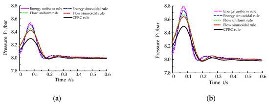
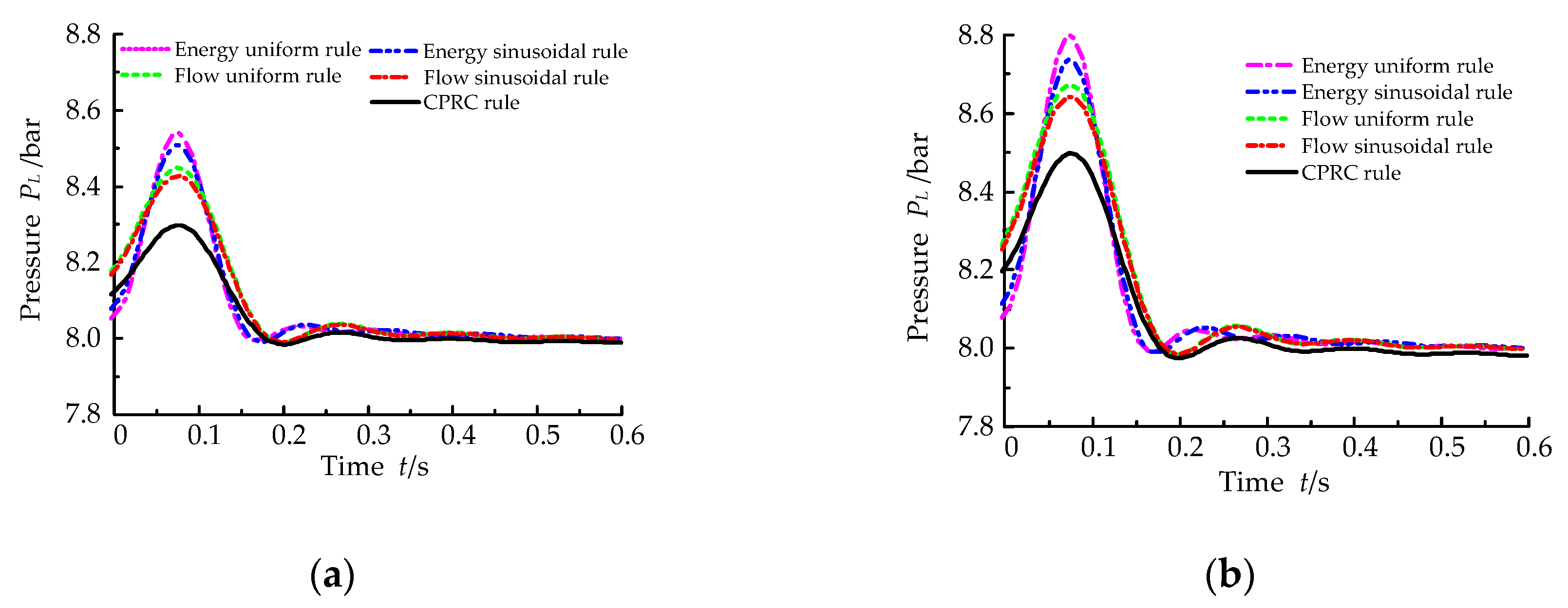
Figure 10.
The pressure response curve of the pressure-relief pipe under initial pressures of 100 bar and 150 bar. (a) 100 bar initial pressure; (b) 150 bar initial pressure.
Figure 10 shows that under the same pressure-relief initial pressure, when the storage energy of the working cylinder changes in accordance with the energy uniform rule, energy sinusoidal rule, flow uniform rule, flow sinusoidal rule, and CPRC rule in turn, the pressure fluctuations of the relief pipe under the above pressure-relief rules is obviously lower than that of the step pressure-relief rule. In addition, the pressure fluctuation peak value and frequency of the relief pipe decrease in turn and are obviously lower than other rules. With the same pressure-relief curve and different initial pressures, as the pressure-relief initial pressure increases and the pressure fluctuation in the relief pipe becomes larger.
6. Experimental Analysis
On the basis of the above theory and simulation analysis, relying on the 0.6 MN forging press experimental platform in our lab, the pressure-relief characteristics of the OCPFHS was carried out to verify the correctness of the theoretical analysis.
6.1. The 0.6 MN Forging Press Experimental Platform
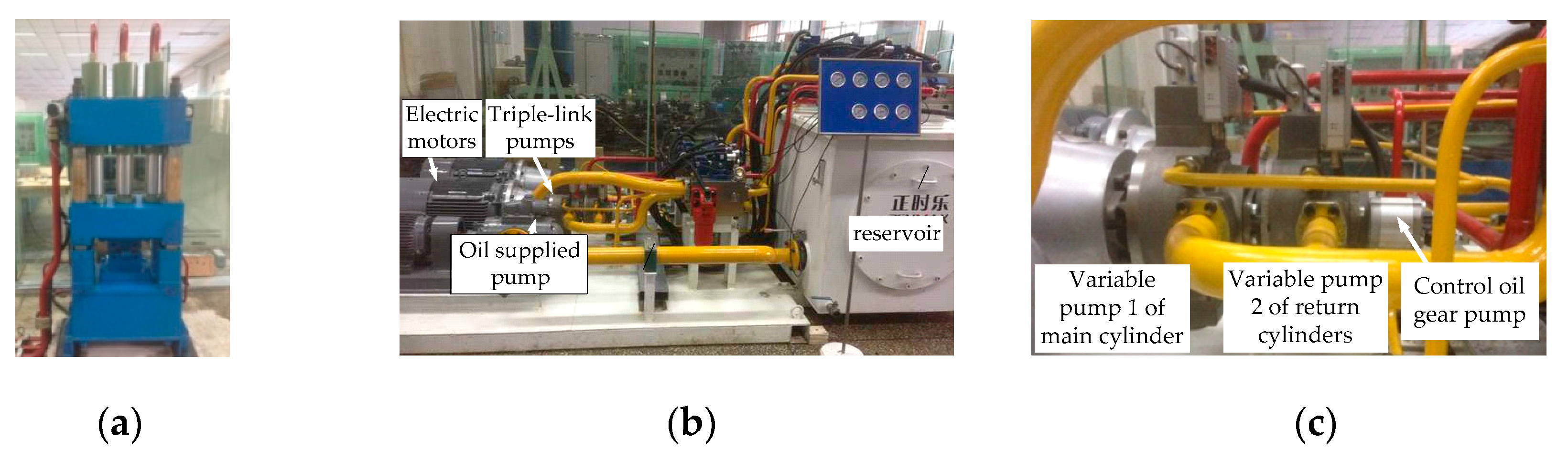
The experimental platform and hydraulic system scheme of OCPFHS (Yanshan University, Qinhuangdao, China) are shown in Figure 11 and Figure 12. The main parameters of the hydraulic system on the 0.6 MIN forging press experimental platform are shown in Table 3. The hydraulic system is mainly composed of tank, motor (Jiamusi Electric Machine Co., Ltd., jiamusi, China), MOOG’s triple-link pump (MOOG China, Shanghai, China), detecting element, and low pressure charge system (Tianjin Huaman Pump Group Co., Ltd., Tianjin, China). The MOOG’s triple-link pump is installed in series by two MOOG’s pumps and one control oil gear pump.
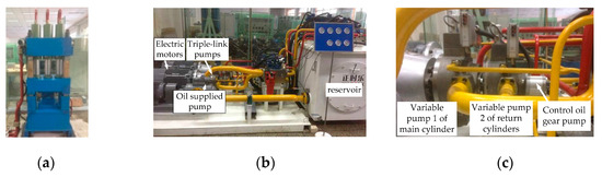
Figure 11.
The test-bed diagram. (a) Hydraulic press body; (b) Hydraulic system of the press; (c) MOOG’s triple-link pumps.

Figure 12.
The test-bed hydraulic system scheme of pump-controlled system.
Table 3.
The hydraulic system parameters of the 0.6MN forging press.
An xPC-Target data acquisition and control system with 0.001 s sample time was used in the electrical control system. The MATLAB/Simulink procedure was programmed and downloaded to the xPC-Target, then the xPC-Target controlled the variable pumps by ACL6126 (D/A conversion). The pressure signals were collected by PCL1716(A/Dconversion). Interface software was developed using Labview (LabVIEW 2010, National Instruments, Austen, TX, USA, 2010) to accomplish the key parameters real-time set and display of the press.
6.2. Pressure-Relief Impact Control Analysis
A step signal was used to relieve pressure of the OCPFHS, and the experimental curves were obtained under the initial pressure of 100 bar, as shown in Figure 13. Figure 13 shows that when the OCPFHS adopts step pressure relief, the working cylinder pressure decreases rapidly, and realizes pressure relief in a short time. However, the working cylinder pressure fluctuates during the descent process, and the peak pressure in the relief pipe is 10.275 bar, which exceeds the steady pressure of 28.43%, indicating that the pressure-relief process produces a strong pressure-relief impact. In the simulation, the pressure of the charge pump in front of the working pump is given a fixed value. However, in the actual system, the charge pump had the problem of flow pulsation, so the final fluctuation phenomenon appeared. In this case, we consider the pressure to be constant. The experiment verifies the existence of pressure-relief impact under a step pressure relief. It is necessary to select a reasonable relief curve according to the system energy storage variation rule to realize the pressure-relief impact control.
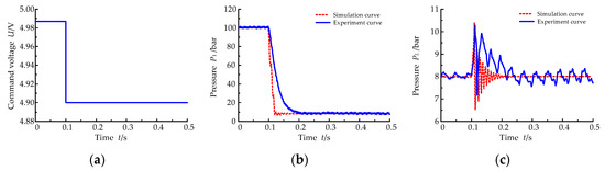
Figure 13.
The experiment curves under the step pressure-relief rule. (a) Eccentric magnitude; (b) Working cylinder pressure; (c) Relief-pipe pressure.
The experiment on the OCPFHS was carried out by using different relief curves. The working-pump eccentric magnitude curves were shown in Figure 8 and Figure 9, the initial pressure was 100 bar and 150 bar, respectively, and the pressure-relief cycle was 0.6 s.
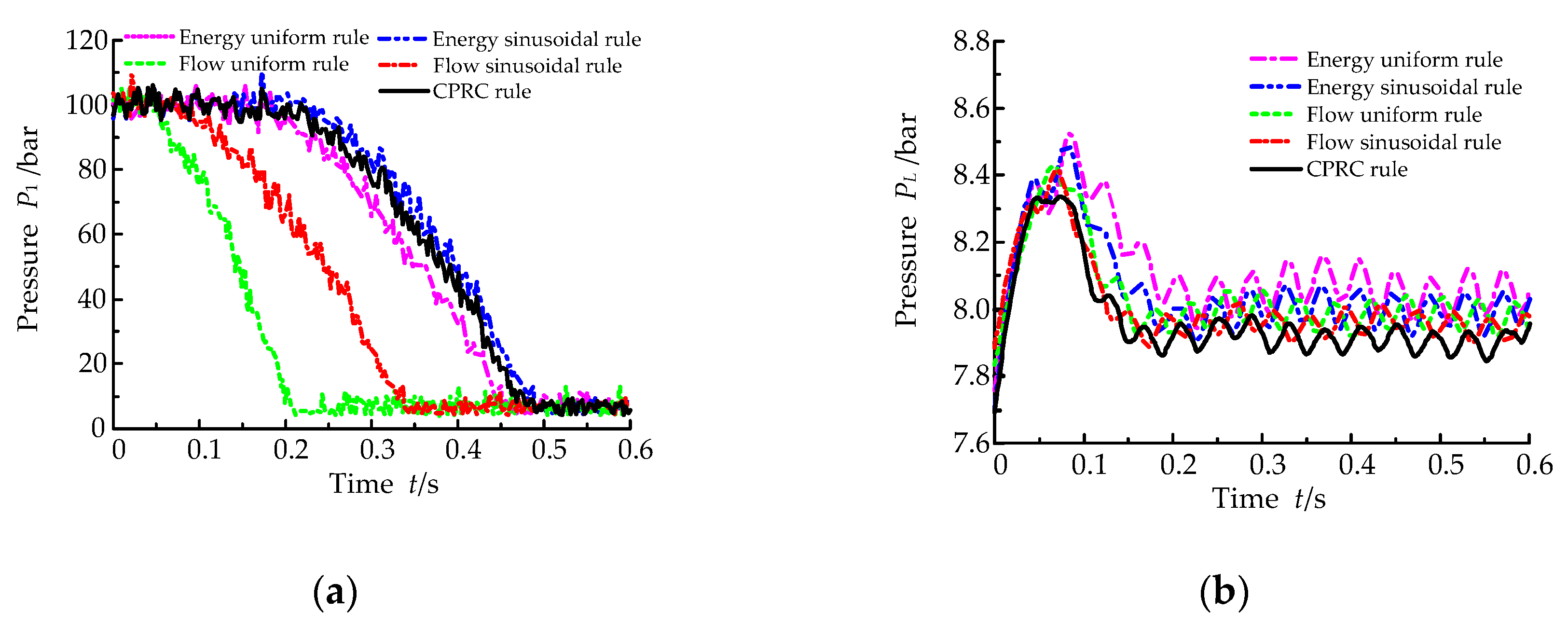
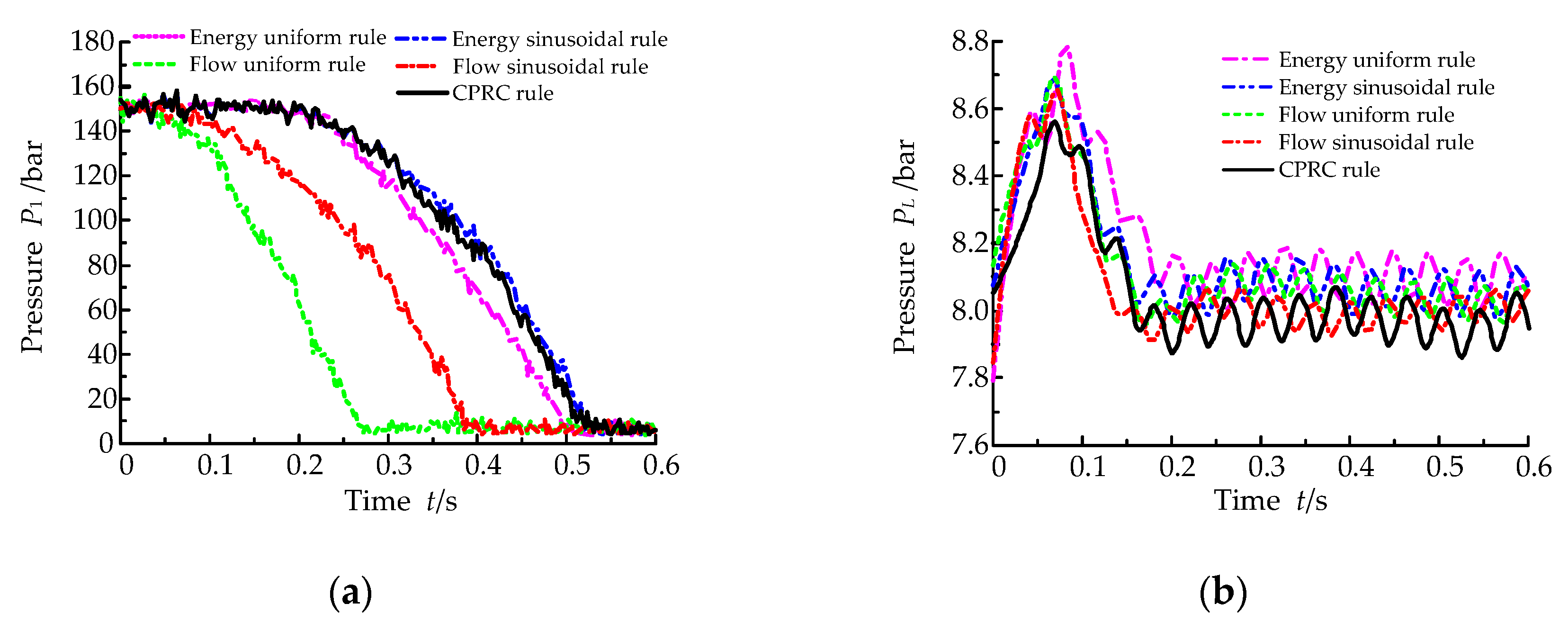
Working cylinder pressure curves and relief pipe pressure curves are shown in Figure 14 and Figure 15. As shown in Figure 14 and Figure 15, the five pressure-relief rules above can achieve a smoother pressure relief, while the relief-pipe pressure fluctuation under the CPRC rule is smaller than that of other rules, When the initial pressure is 10 MPa and 15 MPa, the pressure impact of the pressure-relief tube decreases by 45.45% and 37.5%, respectively, which realizes the smooth pressure relief of the main cylinder. In the simulation, the pressure of the charge pump in front of the working pump is given a fixed value. However, in the actual system, the charge pump had the problem of flow pulsation, so the final fluctuation phenomenon appeared. The experimental and simulation results of the working cylinder pressure-relief process are consistent, but the pressure-relief time in the experiment was faster than that of the simulation results, mainly because the oil is in a high-speed turbulent state during the pressure-relief process. In addition, the oil movement rules are different from the states described by the flow continuity equation. It is impossible to accurately describe the pressure-transmission rule in the pipe.
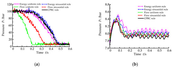
Figure 14.
The system response curve under initial pressure of 100 bar. (a) Working cylinder pressure; (b) Relief-pipe pressure.

Figure 15.
The system response curve under initial pressure of 150 bar: (a) Working cylinder pressure; (b) Relief-pipe pressure.
7. Conclusions
In order to improve production efficiency of the OCPFHS, it is necessary to improve the impact characteristics of pressure relief. One of the key problems for improving the performance of forging hydraulic presses is the control method of pressure-relief impact, which comprehensively considers the period of pressure relief and impact strength. It is difficult to further improve the control performance by using the traditional method of selecting a single rule of pressure-relief curve. Therefore, it is of practical significance to study the pressure-relief curve of low impact OCPFHS. In this paper, the energy storage state of the system before pressure relief was analyzed, and the combined pressure-relief curve model was established. The control methods of quick pressure relief of the main cylinder and low impact of the pressure-relief tube were obtained. The main conclusions are as follows.
(1) In this paper, the pressure-relief impact control method on the OCPFHS was studied. When the OCPFHS adopts step pressure relief, the working cylinder pressure decreases rapidly, and realizes pressure relief in a short time. However, the working cylinder pressure fluctuates during the descent process, and the peak pressure in the relief pipe exceeds the steady pressure of 28%, indicating that the pressure-relief process produces a strong pressure-relief impact. So it is proposed that a reasonable pressure-relief curve is needed to realize the smooth pressure relief.
(2) The method of CPRC was put forward to effectively control the pressure-relief effect of the OCPFHS. The mathematical model of CPRC was established, the working pump eccentric magnitude during the pressure-relief process was planned, and the smooth pressure relief of the working cylinder was realized.
(3) The simulation and experimental research on the pressure-relief impact control of OCPFHS were carried out. The working cylinder response characteristics and relief-pipe pressure response were analyzed under the initial pressures of 100 bar and 150 bar. The results show that in the pressure-relief initial pressure, when the storage energy of the working cylinder changes in accordance with flow uniform rule, flow sinusoidal rule, energy uniform rule, CPRC rule, and energy sinusoidal rule in turn, the working cylinder pressure-relief time increases but it is controlled in the 0.6 s pressure-relief cycle. With the same pressure-relief curve and different initial pressures, as the pressure-relief initial pressure increases, the energy stored in the working cylinder and the pipeline increases, resulting in an increased pressure-relief gradient.
Author Contributions
Conceptualization, X.C. and J.Y.; methodology, X.C., J.Y., and T.S.; validation, X.C. and J.Y.; formal analysis, Y.S.; writing—original draft preparation, X.C.; writing—review and editing, J.Y.; supervision, J.Y.; funding acquisition, J.Y.
Funding
This research was funded by the National Key R&D Program of China, grant number SQ2018YFB200029-03, National Natural Science Foundation of China, grant numbers 51575471 and 51975507, the Natural Science Foundation of Hebei Province, grant number E2018203028, and Hebei Province military and civilian integration industry development special fund project, grant number 2018B070. The authors are grateful for the funding.
Conflicts of Interest
The authors declare no conflict of interest.
References
- Yu, H.Y.; Tang, J.L.; Hu, J. Research on Hydraulic System of Speed Forging Hydraulic Machine. Appl. Mech. Mater. 2012, 192, 123–127. [Google Scholar] [CrossRef]
- Gao, J.; Yan, G.Y.; Peng, G.Y.; Xi, G.N. Experiment study on performances of servo pump used in hydraulic press machine. Adv. Mater. Res. 2012, 516, 892–895. [Google Scholar] [CrossRef]
- Quan, L. Current state, problems and the innovative solution of electro-hydraulic technology of pump-controlled cylinder. Chin. J. Mech. Eng. 2008, 44, 87–92. [Google Scholar] [CrossRef]
- Quan, L.; Xu, X.Q.; Yan, Z.; Zhang, X.J. A new kind of pilot controlled proportional direction valve with internal flow feedback. Chin. J. Mech. Eng. 2010, 23, 60–65. [Google Scholar] [CrossRef]
- Su, W.H.; Jiang, J.H. Direct drive volume control electro-hydraulic servo ship rudder. Key Eng. Mater. 2010, 439, 1388–1392. [Google Scholar] [CrossRef]
- Axin, M.; Eriksson, B.; Krus, P. Flow versus pressure control of pumps in mobile hydraulic systems. Proc. Inst. Mech. Eng. Part I J. Syst. Control Eng. 2014, 228, 245–256. [Google Scholar] [CrossRef]
- Cetinkunt, S.; Pinsopon, U.; Chen, C.; Egelja, A.; Anwar, S. Positive flow control of closed-center electrohydraulic implement-by-wire systems for mobile equipment applications. Mechatronics 2004, 14, 403–420. [Google Scholar] [CrossRef]
- Minav, T.A.; Laurila, L.; Pyrhönen, J.J. Analysis of electro-hydraulic lifting system's energy efficiency with direct electric drive pump control. Autom. Constr. 2013, 30, 144–150. [Google Scholar] [CrossRef]
- Zimmerman, J.; Hippalgaonkar, R.; Ivantysynova, M. Optimal control for the series-parallel displacement controlled hydraulic hybrid excavator. In Proceedings of the ASME 2011 Dynamic Systems and Control Conference and Bath/ASME Symposium on Fluid Power and Motion Control, Arlington, VA, USA, 31 October–2 November 2011; pp. 129–136. [Google Scholar]
- Zhao, H.; Zhang, H.J.; Quan, L.; Li, B. Characteristics of asymmetrical pump controlled differential cylinder speed servo system. Chin. J. Mech. Eng. 2013, 49, 170–176. [Google Scholar] [CrossRef]
- Song, Y.; Kong, X.D.; Yao, J.; Wang, Z. Oil hydraulic press control characteristics with open variable pump-controlled system. China Mech. Eng. 2016, 27, 1031–1038. [Google Scholar]
- Yao, J.; Ren, X.H.; Cao, X.M.; Zhao, J.S.; Kong, X.D. Experimental study on energy consumption characteristics of fast hydraulic forging press with open variable pump-controlled system. China Mech. Eng. 2017, 28, 462–470. [Google Scholar]
- Yao, J.; Wang, P.; Cao, X.M.; Wang, Z. Independent volume-in and volume-out control of open circuit pump-controlled asymmetric cylinder system. J. Zhejiang Univ. Sci. A 2018, 19, 203–210. [Google Scholar] [CrossRef]
- Yao, J.; Wang, P.; Dong, Z.S.; Kong, X.D. Coupling characteristics of independent volume-in and volume-out control for open circuit pump-controlled asymmetric cylinder systems. China Mech. Eng. 2017, 28, 1639–1645. [Google Scholar]
- Ai, C.; Kong, X.D.; Liu, S.K.; Song, Y.; Chen, G. Study on the influence factors of control characteristics of accumulator fast forging circuit for pump-controlled hydraulic press. Forg. Stamping Technol. 2014, 39, 89–95. [Google Scholar]
- Ai, C.; Liu, Y.J.; Song, Y.; Kong, X.D. Research on flow pressure compound position control of open circuit hydraulic pump-controlled forging press system. China Mech. Eng. 2016, 27, 1705–1715. [Google Scholar]
- Prihatin, J.Y.; Kustanto, H.; Pambudi, S.; Nagoro, I.H.A. Study of fluids pressure in hydraulic press machine using L8 orthogonal array. AIP Conf. Proc. 2018, 1, 020005. [Google Scholar]
- Yao, J.; Kong, X.D. Study on process control characteristics of 22MN fast forging hydraulic press. Adv. Mater. Res. 2011, 201, 2258–2262. [Google Scholar] [CrossRef]
- Han, H.Y.; Li, H.Z.; Li, J.; Miao, K.; Wang, J.; Wei, C. Analyzing Nonlinear system stability of a new hydraulic bilateral rolling shear. ISIJ Int. 2016, 56, 1789–1795. [Google Scholar] [CrossRef]
- Henclik, S. Analytical solution and numerical study on water hammer in a pipeline closed with an elastically attached valve. J. Sound. Vib. 2018, 417, 245–259. [Google Scholar] [CrossRef]
- Ding, H.; Zhao, J. Dynamic characteristic analysis of replenishing/leaking parallel valve control systems. Automatika 2017, 58, 182–194. [Google Scholar] [CrossRef]
- Wang, C.B.; Quan, L.; Ou, H. The method of restraining hydraulic impact with active adjusting variable damping. Proc. Inst. Mech. Eng. Part C 2019, 233, 3785–3794. [Google Scholar] [CrossRef]
- Yao, J.; Li, B.; Kong, X.D.; Zhou, F. Displacement and dual-pressure compound control for fast forging hydraulic system. J. Mech. Sci. Technol. 2016, 30, 353–363. [Google Scholar] [CrossRef]
- Zhang, L.; Xu, H.; Pan, C.; Zhang, X.; Zou, T. Analysis of unrestrained curve of rectangular piston ring based on energy principle. In Proceedings of the 2014 13th International Conference on Control Automation Robotics & Vision (ICARCV), Singapore, 10–12 December 2014; pp. 1695–1699. [Google Scholar]
- Fu, L.; Wei, J.; Qiu, M. Dynamic characteristics of large flow rating electro-hydraulic proportional cartridge valve. Chin. J. Mech. Eng. 2008, 21, 57–62. [Google Scholar] [CrossRef]
- Pan, C. Cavity Pressure Relief Process Analysis and Design of a New Relief Valve. Master’s Thesis, Taiyuan University of Technology, Taiyuan, China, 2012. [Google Scholar]
- Zhao, Y. The Modeling and Simulation Study on Cam-Tape Axial Piston Proportional Pump and Hydraulic Hosepipe. Master’s Thesis, Taiyuan University of Technology, Taiyuan, China, 2005. [Google Scholar]
- Shen, W.Q. The Pressure Discharge Impact and Its Reduction Technology Research of Large Press. Master’s Thesis, Central South University, Changsha, China, 2013. [Google Scholar]

© 2019 by the authors. Licensee MDPI, Basel, Switzerland. This article is an open access article distributed under the terms and conditions of the Creative Commons Attribution (CC BY) license (http://creativecommons.org/licenses/by/4.0/).