1. Introduction
Low-voltage active distribution networks (ADNs) comprising distributed generations (DG) such as photovoltaic (PV) solar system, microturbine, wind generation, mini-hydro, and fuel cell have become prominent in the energy sector especially in the existing smart grid setup. This is because the DGs in ADNs are easy accessible, clean, and simplified structures. ADNs are a highly efficient, economic, and reliable form of power grids [
1,
2,
3].
As a result of the distinct features of ADNs, the conventional power system protection approaches that assume high fault current amplitudes and one-way current flow conventions of radial networks are not adequate to operate ADNs [
4].
The main challenge concerning the ADN protection appears where there are high proportion of converter-interfaced renewable energy sources (RESs). In this case, the fault current is relatively low (two times of the peak current) due to the small current rating of the semiconductor apparatuses of the power electronic converters. Consequently, the conventional overcurrent protection scheme cannot sufficiently detect these low fault currents and protect ADNs against severe damages that can be caused by potential network faults [
5,
6,
7,
8]. Although traditional overcurrent protection schemes can be utilized to protect ADNs when there is a strong main (utility) grid connection, the existing relay configurations must be cautiously attuned since the integration of DGs can challenge the harmonization of the protection plan [
4,
9,
10,
11].
There have been a few research works in area of fault protection for ADNs. Admittance-based ADN protection scheme is devised in [
5]. Nevertheless, it could not provide an effective method for determining the precise line admittance for different fault types and places. In addition, the relay coordination was not completely presented in the work.
Network voltage-based fault protection of ADNs and microgrids (MGs) has been proposed by few studies [
6,
7,
12,
13]. The method presented in [
7], for example, uses Park-transformed (d-q frame) network voltage to detect the occurrence of faults in a MG. Nevertheless, it did not measure the d-q components of the network voltages for all kinds of solid faults. It did not guarantee protection for high impedance faults (HIFs) as well. In addition, the method does not define the configuration of the relay that enables the presented protection scheme. The protection method in [
13] applied the d-q components of network voltages for detecting solid faults and wavelet transform-based detection for HIFs. However, the findings of the proposed method are limited to isolated microgrids and its applicability to the ADNs was not considered.
Reference [
8] proposed a protection strategy including its enabling relay to protect low voltage power networks. The strategy provides fault protection for both MGs and ADNs. Nonetheless, it might require a comparatively extensive time to sense faults in a medium voltage (MV) power grids because of the definite time grading technique it uses.
Reference [
14] devised a fast communication-supported fault protection scheme and a microprocessor-based relay in MV power networks. The scheme delivers speedy and coordinated fault clearance for both ADNs and isolated MGs. Nonetheless, the strategy uses under voltage-based method of fault detection that may lead the relays to command false trip signals to circuit breakers (CBs) in case of temporary occurrence of voltage-sags, which all the time present in the power networks because of dynamic variation of load demands and volatility of RESs. Furthermore, the strategy neither guarantees protection for symmetrical HIFs nor delivers techniques for protecting buses.
This study devices a quick and robust fault protection technique for low voltage (LV) ADNs containing high penetration of converter-interfaced renewable energy resources. It uses microprocessor-based digital relay to enable the proposed protection technique. It explicitly provides the configuration of this digital relay. The digital relays operate in coordination detect and clear faults in the ADN. They exchange information with themselves and the central protection manager (CPM). The CPM also exchanges information with the ADN controllers and demand regulation systems. The devised technique provides primary and secondary protections for all solid fault types and HIFs at various possible fault points in the ADN. Numerous simulations are performed on a complete model of an actual ADN using the PSCAD software platform, for various fault locations and types, to substantiate the success of the devised protection technique and enabling relays.
The remaining sections of the study are prepared as follows.
Section 2 offers the configuration of the devised fault protection relay.
Section 3 presents the devised protection technique. The case studies and simulation findings are offered in
Section 4. The study is summarized at the end in
Section 5.
2. Configuration of the Devised Relay
In this study, a communication-aided protection technique is devised for LV active distribution networks. The devised protection technique uses a digital relay to sense the occurrence of fault and segregate the minimum section of the ADN impacted by the fault. The devised protection technique is actuated by the relay that hereafter is said to be the “ADN protection digital relay” (APDR). The focus of
Section 2 is towards describing the architecture, operational units and key components of the APDR. If the APDR communicates with other APDRs, the ADN operator and additional components, it is known as a “communication-aided ADN protection digital relay” (CAPDR).
As aforementioned, the integration of DG causes ADNs or traditional distribution grids encounter a number of confronts, concerning control and protection problems. These problems can be summarized as follows:
bi-directional power flow
limited fault current magnitude
dynamic fluctuations of operating conditions
uncertainty of power generations
Thus, the traditional fault protection methods and relay algorithms are not enough and hence, the protection scheme and relay configurations must be redesigned and modified to operate ADNs safely and reliably [
11]. Particularly, directional components are essential to evade unwanted tripping when faults impact a nearby protection area. The directional component of the neighboring area hastily disable its CB(s), for a specified time, to let the protection (main) components of the fault-impacted area to be activated and remove the fault. If the fault continues, on the other hand, the CB(s) of the neighboring protection area is activated to be opened as secondary protection following the primary protection reverse time-delay.
The proposed protection scheme can be realized using digital relays accessible in the market.
Figure 1 illustrates the functional schematic and operational sections of the devised APDR/CAPDR that is the extended form of the relays provided in [
13,
14]. As depicted in
Figure 1, five units present in the APDR/CAPDR: “directional unit”, “solid fault detection unit”, “HIF detection unit,” “the trip unit,” and “the auto-reclose unit.”
The directional unit decides where the fault current flows using the method that will be discussed in
Section 2.3. The solid fault detection unit is responsible for detecting all type of solid faults in the ADN. It uses the Park transformation of the network voltage as a fault detection signal. The detail analysis and derivation of the detection signal will be discussed in
Section 2.1. The HIF detection unit is responsible for detection HIFs. It employs wavelet transform-based travelling wave fronts of the network current transients. At the end, the yields from the directional unit, solid fault detection unit, and HIF detection unit are applied to the tripping unit to decide the issuance of a tripping signal. The auto-reclosing unit is responsible for ensuring the seamless recoupling of the isolated section of the ADN to the normal section following the clearance of the fault.
2.1. Solid Fault Detection
As discussed in the previous sections, the proposed solid fault recognition methodology relies on the Park transformation of the ADN system voltage. The measured three-phase voltages at the APDR/CAPDR are first transformed to the direct(d)-axis and quadrature(q)-axis (dq) voltage components [
15,
16]. Any change in the three-phase voltage is observed by a change in the dq voltage components [
13]. This study uses the q-axis voltage as the detection signal and it is expressed as follows [
13]:
Here,
Va,
Vb, and
Vc are the 3-phase voltages, and
θ is the phase (transformation) angle.
The disturbance voltage (
Vq.dist) which is used as the fault detection signal is described as:
where,
Vq.ref is a reference q-axis voltage associated with the normal operation of the ADN before the occurrence of the fault.
Under pre-fault condition, the value of Vq.dist is zero. When a fault occurs, Vq.dist is a dc signal that changes based on the fault type.
For symmetrical faults,
Vq.dist is given by:
where,
Vm is the peak of phase voltages and
φ is the phase angle.
For unsymmetrical faults,
Vq.dist is expressed as:
where,
VPm and
VNm are the maximum +ve and −ve sequence phase voltages correspondingly,
ω is frequency, and
φP and
φN are phase angles +ve and −ve sequence phase voltage, respectively.
As observed from Equation (3), for symmetrical (three-phase) faults Vq.dist is a DC signal. While for unsymmetrical faults, as given in Equation (4), Vq.dist is a DC signal plus a sinusoidal component with double frequency (2ω).
Therefore, as per the devised protection technique, the solid fault detection unit of the CAPDR at the end decides the occurrence of a solid fault by contrasting the disturbance voltage (Vq.dist) with a preset threshold value. When Vq.dist is exceeds the preset minimum level, the unit will command a solid fault detection signal (SFDS) to the trip unit of the CAPDR.
2.2. HIF Detection
The traditional overcurrent relays cannot correctly detect HIFs. Although several methodologies have been recommended by prior research works to address the problem (HIF detection) [
17,
18,
19], there is no comprehensive remedy yet. This study provides a technique for HIF detection based on the observation of travelling wave fronts obtained from current transients measured at fault points (branches) [
13,
20].
With this technique, the 3-phase currents in the fault-impacted branches are first converted to the modal components (αβ coordinate) by employing the abc-αβ transform. Afterwards, the wave front (discrete wavelet coefficients (DWTCs)) of the modal constituents is obtained utilizing the discrete wavelet transform (DWT). The αβ branch current constituents are mainly used to obtain the propagation modes in the ADN during the fault occurrence. The DWTCs of each modal component is examined and the DWTC having the biggest amplitude is selected to decide the occurrence of the HIF. At the end, the obtained DWTC is contrasted with a preset threshold to decide they HIF occurrence. The technique has the advantage of being deployed into digital relays.
Therefore, according to the devised protection technique, the HIF detection unit of the CAPDR commands a HIF detection signal (HIFDS) to the trip unit if the fault is sensed. The fault detection signal (FDS) in the trip unit is the resultant of the logical OR of SFDS and HIFDS.
2.3. Directional Decision Forming
The devised technique uses directional units that are provided here according to the methods presented in [
13,
14]. When HIF happens in the ADN, the directional units cannot indicate the precise HIF point. To address this challenge, this study uses zero-sequence directional units; it is similar with the method used in [
21]. In addition, negative-sequence directional unit is utilized to ensure reliable protection for unsymmetrical HIFs, for example line-to-line faults [
8]. At the end, as depicted in
Figure 1, directional commands from zero, −ve, and +ve sequence directional units are merged and used to generate the major directional command D. A unique delay time is employed in either direction of the relays. The relay coordination is performed by regulating the delay times.
3. Proposed Protection Technique
Here, we present the devised communication-aided protection technique, enabled by the devised relay in
Section 2. The devised technique offers primary and secondary protections to solve the ADN protection challenges presented above in
Section 1 and
Section 2.
Based on the devised protection technique, a minimal part of the ADN is separated because of the fault from the healthy section of the ADN through the commands transmitted to one or more CAPDRs. The quantity of CAPDRs used in the ADN is determined according to the preferred selectivity and reliability needs. Every CAPDR that is responsible to protect a particular component or area dispatches 2 commands ADN protection manager (APM):
Fault detection signal (FDS), which indicates if the CAPDR sensed the fault inside its zone
Fault direction signal (D) that specifies the path of the faults from CAPDR perspective.
The APM receives the FDS and D commands from every CAPDR and decides using a suitable logical calculation, the fault affected part of the ADN. The logical calculation is alike the “directional decision” protection technique. It is elaborated more in
Section 4.
When the incidence of the fault is decided (using the FDS), the APM holds-up for a small preset period to receive another directional command and decide the fault-impacted part of the network. Afterwards, appropriate trip signal(s) are dispatched to the CB(s) linked with the CAPDR(s), to open and segregate the faulty part of the ADN. The trip commands are dispatched following a delay-time (in the range (0.1 s, 0.15 s) [
22]) to provide a chance to the adjacent protection elements to operate first. This time setting can guarantee coordination of the CAPDRs with the primary protection adjacent elements.
During a CB malfunctioning, a failure command is commanded to the proximate CBs to isolate the minimum section of the ADN. The CB failure information is sent after a delay-time (in the range (0.3 s, 0.4 s) [
22]) if any FDS is still active. The secondary protection is energized following a delay of 0.4 s from the fault incidence and, therefore, provides an opportunity for the aforementioned two signals to be commanded. Accordingly, if the communication malfunctions and the CAPDRs cannot get any information for a preset time, all CAPDRs will be immediately swapped to the secondary protection. The communications are not needed for the secondary protection except that it requires longer activation time than the primary protection.
The segregated (because of the fault occurrence) section of the ADN can be recoupled back and synchronized to the remaining part of the network through the resynchronization setting of its DGs and reclosing ability of its CBs if the fault is short-term and cleared immediately after the segregation.
The devised protection technique can be realized using the communication abilities of smart grids. Wireless communications [
23], IEEE-802.11 wireless LAN [
24] with Ethernet bridges [
25] and IEC 61,850 [
26] can be some of the communication channels for the application of the devised protection technique.
4. Results and Discussions
To reveal the success of the devised protection technique, the ADN whose schematic framework illustrated in
Figure 2 is used. The ADN in
Figure 2 is an actual LV distribution network in Shenyang, China. The network primarily delivers power to industrial park loads with a peak total demand of 5 MVA.
As depicted in
Figure 2, the ADN comprises four converter-coupled DGs (CC-DGs) and two synchronous machine DGs (SM-DGs). The CC-DGs are the PV system, wind generation, vanadium redox battery (VRB) and lithium-ion (Li-Ion) battery. The capacity of each of these power sources are indicated in the figure. The SM-DGs are the diesel generator and micro gas turbine generation. Hereafter, the ADN of
Figure 2 is called the “case study ADN.”
All the DGs in the ADN normally operate in PQ (fixed active and reactive power) control approach as the main utility grid can always supply the reference voltage and frequency. The detail control approaches of the DGs can be referred from [
27].
As presented above in
Section 2 and
Section 3, every CAPDR sends 2 signals, FDS and D, to the APM. The APM analyses these signals received from the CAPDRs and determines the precise fault point. Then, the trip signals will be sent to the responsible CB(s) to segregate the fault-impacted part of the ADN following a preset delay-time.
Table 1 provides the CAPDRs used for the primary and secondary protections to sense and remove fault from the ADN. During the occurrence faults in the ADN, the D and FDS commands of the corresponding (adjacent) CAPDR(s) are dispatched to the APM. The fault is assumed forward fault if the FDS and D commands have a value of one.
To confirm the efficacy of the devised ADN protection technique and its enabling digital relay, the case study ADN, depicted in
Figure 2, is modeled and simulated using the PSCAD simulation platform [
28]. For CAPDRs in the major protection, the delay-times are set as 100 ms. This offers sufficient time for the tripping unit not to send false signal for temporary voltage dips in the network. The time-delay CAPDRs/APDRs in the secondary protection is set as 400 ms. The CBs need 20 ms for opening or closing. In addition, the CAPDRs are implemented with double-setting directional units in order to provide both primary and secondary protections when needed.
Likewise, the reverse time-delays of CAPDRs are set according to common practices and the techniques provided in [
8] and obviously have dissimilar values from the forward time-delays since there might be distinct DG and load in the reverse direction. The q-axis reference voltage is set as the q-axis rated value. The threshold voltage is taken as 50% of the rated voltage for double line to ground (DLG), 3-line to ground (3LG) and line-to-line (LL) faults, while 20% is used for single line to ground (LG) fault. The Daubechies 8 (Db8) DWT with a sampling frequency of 6 kHz and multiresolution analysis (MRA) of unity resolution is used for the HIF detection.
The simulations consist of faults at various points in the ADN. These faults are F1, F2, F3, F4, F5, and F6 (illustrated in
Figure 2) which designate faults at the PV DG terminal, Load1 terminal, distribution line, bus, microturbine DG terminal, and Load4 terminal, correspondingly. All solid faults (LG, DLG, LL, and 3LG) and HIFs are considered in the protection simulation. A resistance value of 60Ω is employed to simulate the HIFs.
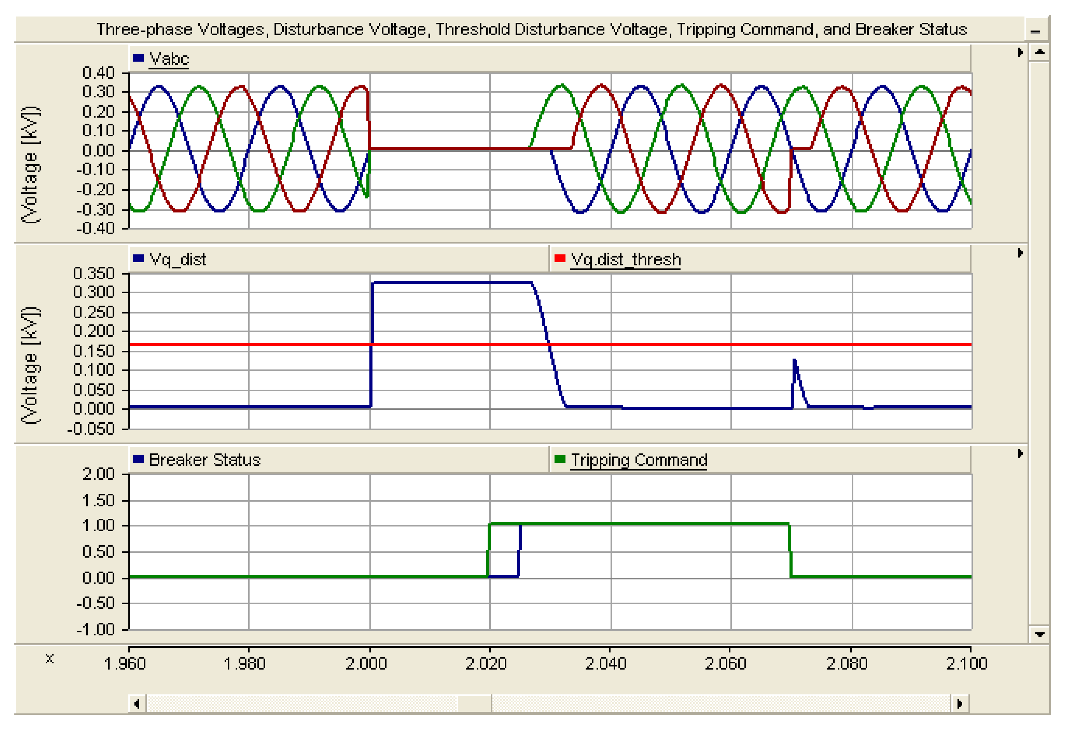
For the photovoltaic DG, the primary protection is provided by CAPDR31 while F1 happens near to its terminal.
Figure 3 illustrates the 3-phase voltages and q-axis disturbance voltage observed at CB31 while F1 (3LG) occurs. As observed in
Figure 3, the disturbance voltage has varied considerably when F1 happened, and surpassed the preset threshold level. As shown, the disturbance voltage is a fixed DC value for a 3LG fault. As
Figure 3 shows, F1 happened at 2 s and remained for 0.05 s. The CAPDR sensed F1 using the substantial variation in the q-axis voltage and dispatched the trip command at 2.02 s. CB31 opened at 2.025 s to cut off the DG and segregate it from the remaining part of the ADN. F1 cleared at 2.05 s and the CB reclosed at 2.07 s. It is shown that the ADN voltage has recovered its normal value straightaway following the disappearance of F1 through the reclose function of the devised relay. It demonstrates the rapidity of the devised technique and its quick information exchange capability.
For Load1, primary protection in direction1 is provided by CAPDR16 and secondary protection by CAPDR15 when F2 happens.
Figure 4 depicts the 3-phase voltages, q-axis disturbance voltage, and DWTC (wave front) of current-transient observed at CB16, while F2 (DLG HIF) occurs. As shown in
Figure 4, the q-axis voltage altered very little when F2 happened. It is smaller than the preset threshold level. Consequently, the q-axis disturbance voltage cannot sufficiently activate the CAPDR to dispatch a tripping command to the responsible CB. Nevertheless, the DWTC has revealed a substantial variation (surpasses the zero threshold level) while the DLG HIF (F2) happened. F2 happened at 2 s. The CAPDR has sensed F2 using the substantial alteration of the DWTC and sent trip signal to CB16 to cut off Load1 and separate it from the healthy part of the ADN.
CAPDR12 in direction1 and CAPDR13 in direction2 are in charge of the primary protection for Line1 when F3 happens. CAPDR21 for CAPDR12 and CAPDR14 for CAPDR13 are the corresponding secondary protections in direction2.
Figure 5 depicts the 3-phase voltages and q-axis disturbance voltage observed at CB13 when F3 (LG) happens. As clearly seen, the q-axis voltage varies considerably while F3 has happened and surpasses the preset threshold. The q-axis voltage in this case is a DC signal plus a ripple element with a double frequency. F3 happened at 2 s and remained for 0.05 s. Both CAPDRs sensed F3 and sent trip commands at 2.02 s. CB12 and CB13 opened at 2.025 s to separate Line1 and separate it from the healthy part of the ADN. F3 cleared at 2.05 s and the CBs reclosed at 2.07 s.
CAPDR12, CAPDR21, CAPDR32, and CAPDR41 are in charge of primary protection of Bus1 when F4 happens. The APM determines bus faults using the direction commands (Ds) obtained from the CAPDRs coupled with the bus. It decides the incidence of the bus fault if all the Ds sent from every relay coupled with the bus are negative one (−1). The trip commands are then dispatched to all responsible CBs.
Figure 6 depicts the 3-phase voltages, q-axis disturbance voltage, and current DWTC observed at CB21, while F4 (LL HIF) occurs. Similar outcome can be attained at CB12, CB32, and CB41 as well. As shown, the DWTC surpasses the zero threshold when F4 happened. F4 happened at 2 s. The CAPDRs sensed F4 and sent the trip commands to the responsible CBs to segregate Bus1 from the remaining part of the ADN.
Similarly,
Figure 7 and
Figure 8 illustrate the 3-phase voltages and q-axis disturbance voltage observed at CB27 when F5 (3LG) occurs and at CB26 when F6 (LG) occurs, respectively.


