Abstract
For low speed diesel engines under severe ocean conditions, high efficiency air–water separators must be equipped to separate excess moisture contained in the air and reduce the corrosion. Optimal design of air–water separator is an indispensable part in the development of marine main engines. In view of the complex gas–liquid two-phase turbulent motion within an air–water separator with corrugated plates, a mathematical model is established and numerical simulations of flow field, droplet trajectory and secondary transport are realized. The separation efficiency and pressure drop of the air–water separator under different structure parameters and different working conditions are studied. The results show that reducing the spacing of corrugated plate is helpful to improve the separation efficiency. The bending and hydrophobic hooks of the corrugated channel are important to improve the separation efficiency. The separation of droplet is mainly concentrated on the first two stages of the air–water separator, and the separation efficiency at the third stage is significantly reduced. Research results will further support corrugated plate theory, experimental research and optimization design of similar separators.
1. Introduction
When air entering the marine diesel engine passes through the supercharger and the air cooler of the diesel engine, the moisture contained in the air condenses together to form water droplets. The water droplets are brought into the scavenging box and cylinder of the diesel engine by the pressurized air, causing the damage to the oil film on the cylinder and aggravating the corrosion and wear of the cylinder, exhaust valve and piston ring, which results in the decline of the power and economic performance of the diesel engine. In the case of high atmospheric humidity and low sea temperature, condensation phenomenon will become more serious. Therefore, air–water separators are essential equipment in the intake system of marine diesel engines.
Due to complex flow around internal components such as rectification and junction structures, there is a lack of in-depth research on the mechanism how these components affect separation efficiency of separators. In recent years, rapid development of multiphase flow theory and computer technology has greatly promoted theoretical study gas–liquid separators. By comparing with experimental research and numerical simulation technology can save cost, greatly shorten research period and can reveal different component flow fields within specific influence of each area.
Zhao et al. [] and Bogodage et al. [] used single particle dynamics model to numerically calculate the moving track and separation efficiency of water droplets in the corrugated plate and pointed out that the deflection angle of the corrugated plates should not be greater than 45°. Li et al. [] calculated droplet trajectory phenomenon and separation efficiency and found that the droplets flow velocities at different inlets corresponded to a critical particle size and the critical value decreased with the increase of the inlet droplets velocity. Francesco [] studied the performance evaluation and optimization of the cyclone separator in terms of particle separation and heat transfer efficiencies, while keeping pressure losses under control. Nagdewe et al. [] performed a parametric analysis to get higher efficiency for air-liquid separators and optimal design parameters are gained based upon obtained results of tangential velocities, vortices, total pressure losses. Behin et al. [] studied the single-stage separation efficiency, total separation efficiency and pressure drop of a double-hooked corrugated plate separator under hot condition by means of numerical simulation. Chen et al. [] numerically studied the effects of parameters such as air velocity, droplet size, folding plate form, spacing and installation mode on the separation efficiency and pressure drop of a folded plate air-liquid separator and achieved good comparison numerical results with the cold state experimental results. Le et al. [] developed a 3D multiphase Eulerian computational fluid dynamics to investigate the effect of a simultaneous three-angular motion on the performance of an air-water-oil separator. Shastri et al. [] numerically investigated the effect of varying height ratios of cylinder and cone on the performance of the cyclone separators and found the cylinder-to-cone ratio affected the fluctuating field much more than the mean flow field. Gao et al. [] proposed a new Q criterion to analyze the vortex in cyclones that had various inlet structures. The Reynolds stress model (RSM) was used to simulate the gas flow and found the vortex structure was intuitive according to the new isovortex surface that was obtained. Zhang et al. [] studied the flow field and separation efficiency of a high gravity rotary gas–liquid separator by CFD techniques and compared the numerical results with the available experimental data. Dasar et al. [] reshaped the cylindrical portion of conventional cyclone separator by fixing triangular, semicircular and rectangular cross section helical fins to improve separation efficiency. Fluid dynamic characteristics were numerically studied by varying the fin geometry and found the cyclone separators can be used as heat exchangers for energy conservation in industrial applications.
For large marine diesel engines providing power propulsion for large vessels, an air–water separator with corrugated plates must be arranged to separate excess moisture contained in the air and reduce the corrosion. In order to evaluate the separation performance of air–water separators with different corrugated plates and to select the most appropriate separator for the studied marine diesel engine, a numerical procedure is proposed and expected to present valuable data for performance parameters. Based on the three-dimensional discrete phase model (DPM), a numerical model is established and numerical simulations of flow field, droplet trajectory and secondary transport are realized. An implicit solver based on pressure is applied to consider the large pressure gradient characteristics of the flow field by using SIMPLE algorithm. The separation efficiency and pressure drop of the air–water separator under different structure parameters and different working conditions are studied by calculating and analyzing the flow of two phases inside the air–water separator.
2. Structure and Separation Principle of the Air–Water Separator
Air–water separator with corrugated plates is an effective gas–liquid separation device. When the gas and liquid after enter corrugated plates at low speed along the waveform of the corrugated plates of orbit curve movement and hit the corrugated plate in corner, water droplets are formed by inertia force and molecular friction between water droplets and corrugated plates. When the droplets are large enough, its weight will be greater than the force of adhesion and the buoyancy of the air flow on it; therefore, they will drop and fall to the bottom of the corrugated plates. Further, the droplets are stuck on the corrugated plates and gradually form a thin water film. Subsequently, the separated droplets collide with the water film on the corrugated plate wall, and sink on the water film. The formed water film flows downwards continuously by its own weight and accumulates droplets in the lowest part of the corrugated plates. The separation process is a complex process involving two-phase flow, swirl flow, cyclone, separation and phase change [].
The schematic diagrams of the studied air–water separator with corrugated plates are shown in Figure 1 and Figure 2. The air–water separator mainly includes corrugated plates, cyclone and net cushion. The width and height of the main working body of the air–water separator are W and H, respectively. The structural parameters of the single channel of the air–water separator mainly include total width of the air–water separator W, total height of the air–water separator H, length of each corrugated plate L, spacing between two corrugated plates B and turning angle of corrugated plates α.
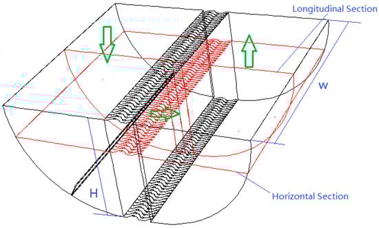
Figure 1.
Structure of the studied air–water separator.
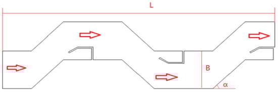
Figure 2.
Single channel structure of the air–water separator.
The basic structure size of the studied air–water separator and air inflow parameters of the separator under different loads are listed in Table 1 and Table 2. SMCR in Table 2 is the abbreviation of specific maximum continuous rating of a marine main diesel engine.

Table 1.
Basic structure size of the air–water separator.
Table 2.
Air inflow parameters of the separator under different loads.
3. Mathematical Model of the Air–Water Separator with Corrugated Plates
According to air–water two-phase flow in the air–water separator, the discrete phase model in the Lagrange coordinate system is used to simulate the particle motion, and the air phase is considered as continuous phase [,]. In the discrete phase model, the droplet motion is described by Lagrange method. The basic assumption is that there is no collision and polymerization between the droplets, the droplets are ideal spheres that are not deformed, and the droplet is completely captured by the plate wall when it reaches the wall of the corrugated plates []. The gas phase is incompressible air in steady state without consideration of buoyancy lift and internal friction heat dissipation. There is velocity slip between droplets and air; droplet groups are not used as continuous media but are grouped according to their initial size rather than local size; the droplets move in their respective orbits and do not interfere with each other. There is no collision or polymerization between the droplets. The droplets are ideal spheres with no deformation or rotation. There is no turbulent diffusion of each droplet itself.
The continuous equation and the momentum equation can be written as Equations (1) and (2), respectively.
The turbulent K equation and ε equation can be written as Equations (3) and (4), respectively.
where Gk is the turbulent flow energy produced by the laminar velocity gradient, Gb is the turbulent flow energy generated by buoyancy, YM is a fluctuation caused by excessive diffusion in incompressibility, , , and are constants,
and are the Prandtl number of K equation and ε equation.
An implicit solver based on pressure is applied to consider the large pressure gradient characteristics of the flow field by using the format of PRESTO! pressure interpolation. The method of coupling pressure and velocity is using the SIMPLE algorithm [,,].
Table 2 gives out the simulated air inflow parameters of the separator under different loads. Different kinds of boundary conditions including the inlet, outlet and solid wall are employed to close the equations. Inlet boundary condition is set to mass flow inlet varying with mass flow rate of air inflow under different loads; outlet boundary condition is set to outflow type. The wall boundary conditions are divided into two categories: (a) boundary conditions of the waveform partition of the surfaces and hydrophobic hooks are set to “trap” which means the wall will trap droplets phase and lead the termination of calculation; (b) the rest of the solid wall surface is set as no slip boundary condition and the wall function method is adopted for the treatment of the near-wall area.
In the calculation process, water droplets in the air are analyzed as discrete phases. Firstly, the distribution of droplet size employs Rosin–Rammler distribution description in which all particle sizes are divided into size groups representing an average particle size. Particles’ trajectory is calculated according to the average particle diameter.
4. Analysis of the Numerical Simulation Results
4.1. Characteristics of the Two Phase Flow Field
Based on the above model and numerical process, detailed numerical simulation of running performance of the studied air–water separator under different loads is carried out, and the distribution of pressure, velocity and concentration in the air–water separator is obtained and analyzed. According to the operation load of the low-speed marine diesel engine, 6 groups of representative working conditions are selected.
In order to illustrate the distribution characteristics of the flow field, two sections of the flow field are selected to analyze, and the relative position of the sections are shown in Figure 1. In the analysis of the cross section, on the two sides of the wave channel the structure is simple and the change of the flow field is not very obvious, so the local part of the corrugated plate channel is directly analyzed. The typical velocity distributions of the air phase in the separator are shown in Figure 3. From Figure 3a, it can be seen that the presence of baffle at the 90 degree bend makes the velocity behind the baffle increase in the bend area. Figure 3b shows that the existence of a hydrophobic hook and the curvature of the flow passage cause the unevenness of the velocity distribution, and a low speed zone are correspondingly generated inside and behind each of the hook grooves. The maximum velocity in the flow field exists in the top area of the hydrophobic hook, and the low speed zone is at the bend of the corrugated plate. There is a distinct vortex at the back of the hydrophobic hook, which is a low speed recirculation zone.
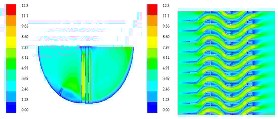
Figure 3.
Velocity field distribution of the separator in different directions, m/s. (a) Longitudinal section. (b) Cross section.
In Figure 4, one can see that the total pressure decreases gradually along the flow direction, and the low pressure area behind the hydrophobic hook at the end of the third stage is relatively large, which shows that the hydrophobic hook has a great influence on the flow field distribution of the corrugated plate channel. The total pressure behind the hydrophobic hook drops sharply near the recirculation zone, and the loss increases significantly. Due to the effect of mixing, the total pressure increases after the recirculation zone.
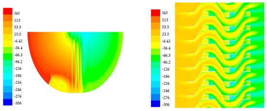
Figure 4.
Total pressure distribution in different section, Pa. (a) Longitudinal section. (b) Cross section.
In the cloud diagram of the droplet phase concentration distribution shown in Figure 5, at the first 90 degrees of the bend, the concentration of droplet phase in contact with the wall surface in front of the baffle is very low because of the presence of the baffle, however, the concentration of the droplet phase in the space near the wall is very low. After a period of aggregation, the droplets flow down the wall to the lowest point of the structure of the air separator and then separate out. It is the existence of the baffle that makes the airflow velocity behind the baffle very low, which reduces the possibility of the droplet being carried twice and improves the separation efficiency. It is evident from Figure 5b that most of the droplets have been separated at the first two levels. Only the droplets with very small diameters are trapped by the airflow and are not separated because of the smaller inertia force, thus eventually escaping with the air flow.
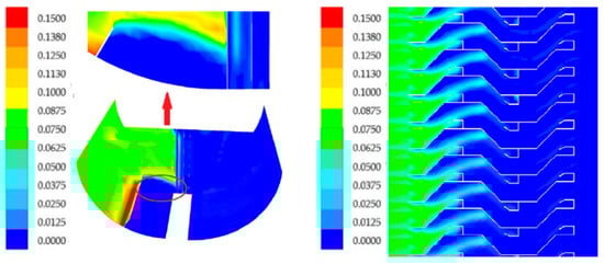
Figure 5.
Droplets phase concentration distribution in different section. (a) Longitudinal section. (b) Cross section.
4.2. Influence of Structural Parameters on the Performance of the Air–Water Separator
Several structural parameters affect the pressure loss and separation efficiency of the air–water separator, including the shape of the corrugated plate, the spacing, the size of the turning angle, the existence of the hydrophobic hook and the position of the structure. Under different loads of the main diesel engine, the performance of the air–water separator is numerically calculated under the conditions of different corrugated plate spacing, different turning angle of the outlet and the separator with or without the third stage hydrophobic hook.
Figure 6 and Figure 7 show the effect of the spacing of the corrugated plates on the pressure loss and separation efficiency of the separator under different loads. It can be seen that the spacing of the corrugated plates has a great influence on the pressure loss. When the spacing is reduced to 20 mm, the total pressure drop increases greatly, this is about 50%. The third terminal hydrophobic hook plays an important role in the aerodynamic performance. After removing the hydrophobic hook, the aerodynamic performance of the corrugated plate is greatly improved. In Figure 7, the separation efficiency is slightly increased with the decrease of the spacing of the corrugated plate, and the separation efficiency is the lowest after removing the third stage of hydrophobic hooks, but it is still within the permissible range.
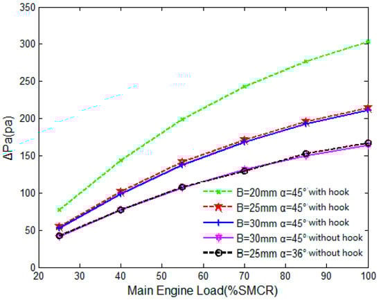
Figure 6.
Influence of corrugated plate spacing on the total pressure loss.
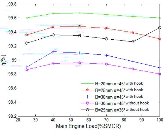
Figure 7.
Influence of corrugated plate spacing on the separation efficiency.
Figure 8 and Figure 9 show the effect of the turning angle of the corrugated plate outlet on the pressure loss and separation efficiency of the air–water separator under different loads. It can be seen that the influence of the turning angle on the pressure drop of the air–water separator and the total separation efficiency is not obvious. This is because the improvement of the turning angle is only aimed at the structure of the third stage. If the turning angle of the whole structure is improved, the performance of the air–water separator will be changed certainly.
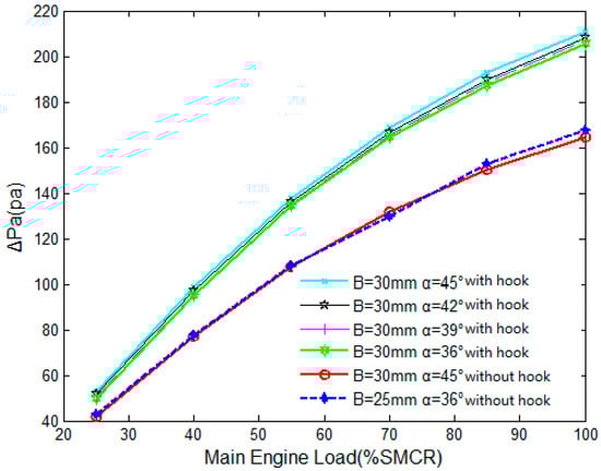
Figure 8.
Influence of corrugated plate turning angle on the total pressure loss.
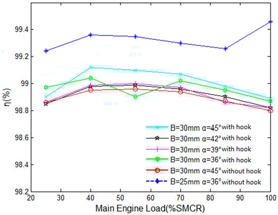
Figure 9.
Influence of the turning angle of corrugated plates on separation efficiency.
Table 3 gives the calculated results of pressure loss and separation efficiency of the air–water separator under eight different structural parameters. One can obviously see that the pressure loss is greatly affected by the 3rd stage hook which can cause 40 plus Pascal pressure loss comparing to cases without such hook. From the data of eight groups of pressure loss in the table, it can be seen that the pressure loss of the air–water separator under the condition of the last two structural parameters is relatively much small.
Table 3.
Pressure loss and separation efficiency under different structure parameters.
5. Conclusions
In this paper, the internal two-phase flow and separation performance of an air–water separator for a low speed marine diesel engine are studied comprehensively by means of numerical simulation. From the two aspects of resistance characteristics and separation efficiency, the influence of different structure parameters on the performance of the studied air–water separator is calculated and analyzed under different conditions.
Through the numerical simulation of the three-dimensional integral structure of the air–water separator and the numerical simulation of the two-phase flow with the droplet as the discrete phase, it is concluded that the pressure loss mainly exists in the area of corrugated plate in the middle of the air–water separator. The turning angle and the hydrophobic hook are the main factors leading to the pressure loss, but at the same time it is also the main factor to improve the separation efficiency. At the turning point of the first 90 degrees, the baffle is designed to reduce the possibility of the droplet being carried twice and to improve the separation efficiency.
Different structural parameters of the air–water separator by changing the spacing of the corrugated plates, the size of the turning angle and whether there is a hydrophobic hook or not are analyzed. The results show that the spacing of the corrugated plates has a great influence on the pressure loss, and the separation efficiency increases slightly with the decrease of the spacing of the corrugated plates. The effect of the angle of the outlet of the corrugated plate on the pressure drop and separation efficiency of the air–water separator is not obvious. The third-stage terminal hydrophobic hook has a great influence on the aerodynamic performance. After removing the hydrophobic hook, the aerodynamic performance of the corrugated plate is greatly improved, but it has little effect on the separation efficiency. The third-stage hydrophobic hooks can be cancelled to simplify the structure of the corrugated plate and reducing the total cost.
Author Contributions
Conceptualization, Z.M. and Y.C.; methodology, Z.M.; validation, Y.C. and J.T.; formal numerical investigation, J.T.; data curation, Z.M.; writing—original draft preparation, J.T. and Z.M.; writing—review and editing, J.T. and Z.M.; project administration, Z.M.; funding acquisition, Z.M. All authors have read and agreed to the published version of the manuscript.
Funding
This research was funded by Qing-Lan Project of Jiangsu Province (Grant No.: 161220605), and the Scientific Research Foundation of Nanjing Forestry University (Grant No.: GXL2018004).
Acknowledgments
In this section you can acknowledge any support given which is not covered by the author contribution or funding sections. This may include administrative and technical support, or donations in kind (e.g., materials used for experiments).
Conflicts of Interest
The authors declare no conflict of interest.
Nomenclature
| α | turning angle of corrugated plates, ° |
| B | spacing between corrugated plates, m |
| turbulent dissipation | |
| Gk | turbulent flow energy produced by laminar velocity gradient |
| Gb | turbulent flow energy generated by buoyancy |
| H | Total Height, m |
| i,j | x, y, z direction |
| k | turbulence kinetic energy |
| L | length of corrugated plate, m |
| air mass flow rate, kg/s | |
| droplets mass flow rate, kg/s | |
| SMCR | specific maximum continuous rating of marine diesel engine |
| density of inflow air, kg/m3 | |
| viscosity of inflow air, Pa·s | |
| p | pressure of air, MPa |
| Δp | pressure loss, Pa |
| η | separation efficiency, % |
| Prandtl number of K equation | |
| Prandtl number of ε equation | |
| u | instantaneous velocity, m/s |
| YM | fluctuation coefficient caused by excessive diffusion in incompressibility |
| W | width, m |
References
- Zhao, L.X.; Li, Y.Q.; Xu, B.R.; Jiang, M. Design and Numerical Simulation Analysis of an Integrative Gas-Liquid-Solid Separation Hydrocyclone. Chem. Eng. Technol. 2015, 38, 2146–2152. [Google Scholar] [CrossRef]
- Bogodage, S.G.; Leung, A.Y.T. CFD simulation of cyclone separators to reduce air pollution. Powder Technol. 2015, 286, 488–506. [Google Scholar] [CrossRef]
- Li, J.; Huang, S.; Wang, X. Analysis of the influence of turbulent flow effect on the corrugated plate stream-water separators with drain hooks. Chem. Eng. Mach. 2008, 36, 282–286. [Google Scholar]
- Francesco, R.; Claudio, P. Heat exchange and separation efficiency in a cluster of air-solid separators in a complex cement production plant. Energy Procedia 2015, 82, 886–892. [Google Scholar]
- Nagdewe, J.K.; Kwoon, H.D.; Kim, D.S.; Kim, K.M. A Parametric Study for High-Efficiency Air-Liquid Separator Design. J. Therm. Sci. 2008, 17, 238–242. [Google Scholar] [CrossRef]
- Behin, J.; Azimi, S. Experimental and Computational Analysis on Influence of Water Level on Oil-Water Separator Efficiency. Sep. Sci. Technol. 2015, 50, 1695–1700. [Google Scholar] [CrossRef]
- Chen, J.; Hou, J.; Li, G.; Chen, J.; Xu, C. The Effect of Pressure Parameters of a Novel Dynamic Hydrocyclone on the Separation Efficiency and Split Ratio. Sep. Sci. Technol. 2015, 50, 781–787. [Google Scholar] [CrossRef]
- Le, T.T.; Ngo, S.I.; Lim, Y.I.; Park, C.-K. Effect of simultaneous three-angular motion on the performance of an air-water-oil separator under offshore operation. Ocean Eng. 2019, 171, 469–484. [Google Scholar] [CrossRef]
- Shastri, R.; Brar, L.S. Numerical investigations of the flow-field inside cyclone separators with different cylinder-to-cone ratios using large-eddy simulation. Sep. Purif. Technol. 2020, 249, 117149. [Google Scholar] [CrossRef]
- Gao, Z.W.; Wang, J.; Liu, Z.X.; Wei, Y.; Gao, Z. Effects of different inlet structures on the flow field of cyclone separators. Powder Technol. 2020, 372, 519–531. [Google Scholar] [CrossRef]
- Zhang, Z.; Wang, H.; Ma, J.; Ling, X. Numerical Study on a Novel Type of High Gravity Rotary Gas-Liquid Separator. J. Appl. Fluid Mech. 2020, 13, 969–979. [Google Scholar] [CrossRef]
- Dasar, M.; Patil, R.S. Studies on Separation Efficiency and Energy Conservation Through Novel Finned Cyclone Separator. J Heat Transf. Transact. 2020, 142, 4. [Google Scholar] [CrossRef]
- Chira, G.A. Numerical model for air flow and droplet motion in wave-plate mist eliminators with drainage channels. Chem. Eng. Sci. 2008, 63, 5639–5652. [Google Scholar]
- Vander, W.; Randy, L.; Berger, G.M.; Mozes, S.D. Droplets splashing upon films of the same fluid of various depths. Exp. Fluids 2006, 40, 33–52. [Google Scholar] [CrossRef]
- Schmitt, V.; Dufresne, M.; Vazquez, J.; Fischer, M.; Morin, A. Separation efficiency of a hydrodynamic separator using a 3D computational fluid dynamics multiscale approach. Water Sci. Technol. 2014, 69, 1067–1073. [Google Scholar] [CrossRef] [PubMed]
- Yu, X.; Makkawi, Y.; Ocone, R.; Yu, X.; Huard, M. A CFD study of biomass pyrolysis in a downer reactor equipped with a novel gas-solid separator-I: Hydrodynamic performance. Fuel Process. Technol. 2014, 126, 366–382. [Google Scholar] [CrossRef][Green Version]
- Guizani, R.; Mokni, M.H.; Mhiri, H.; Bournot, P. CFD modeling and analysis of the fish-hook effect on the rotor separator’s efficiency. Powder Technol. 2014, 264, 149–157. [Google Scholar] [CrossRef]
- Lakghomi, B.; Taghipour, F.; Posarac, D.; Watkinson, P. CFD simulation and experimental measurement of droplet deposition and hydrocarbon fouling at high temperatures. Chem. Eng. J. 2011, 172, 507–516. [Google Scholar] [CrossRef]
- Elsayed, K.; Lacor, C. Optimization of the cyclone separator geometry for minimum pressure drop using mathematical models and CFD simulations. Chem. Eng. Sci. 2010, 65, 6048–6058. [Google Scholar] [CrossRef]
Publisher’s Note: MDPI stays neutral with regard to jurisdictional claims in published maps and institutional affiliations. |
© 2020 by the authors. Licensee MDPI, Basel, Switzerland. This article is an open access article distributed under the terms and conditions of the Creative Commons Attribution (CC BY) license (http://creativecommons.org/licenses/by/4.0/).