Abstract
Gas pollution in marine lubricating oil systems is harmful to the normal operation of a ship, and is one of the main reasons for the decline of the performance of lubricating oil. In this research, a classic 75 mm hydrocyclone was selected as the oil–gas separation device. A hydrocyclone is a device that uses the density difference of the two-phase flow to separate the dispersed phase in the centrifugal force field. Compared with ordinary active oil–gas separators, hydrocyclones do not require additional power devices. After establishing the physical model of the hydrocyclone, the distribution characteristics of the flow field and oil–gas two-phase flow separation performance of the hydrocyclone were studied using computational fluid dynamics (CFD) technology. The influence of vortex finder diameter, vortex finder length, spigot diameter, cylindrical-part length, and cone angle on the oil–gas separation performance of the hydrocyclone were investigated. It was found that the vortex finder diameter and the spigot diameter have a significant influence on the oil–gas separation performance, whereas the vortex finder length, the cylindrical-part length, and the cone angle have little influence on its performance. Increasing the vortex finder diameter and reducing the spigot diameter can improve the gas separation efficiency. However, the liquid outflow from the vortex finder increases, which causes the liquid loss rate to increase. The presented research could lay a foundation for the optimal design of a hydrocyclone used for oil–gas separation of a marine lubricating oil system.
1. Introduction
Due to the trend of economic globalization, the global transportation industry, of which marine transportation accounts for 90%, has grown rapidly [1]. The power system is the core of a ship’s systems, and mainly includes the primary engine, power transmission system, propeller, auxiliary system, control system, and power supply system [2,3]. The lubricating oil system is an important auxiliary system that guarantees the stable operation of the ship’s primary engine. It not only supplies a proper amount of lubricating oil to the friction surfaces of the moving parts of the engine to reduce friction, but also has the functions of cooling, air tightness, rust prevention, etc. [4,5]. In general, the lubricating oil is mixed with some amount of air. When the lubricating oil passes through the oil pump, pipeline, and high-speed bearing, a large amount of free air and gas is pumped back to the lubricating oil, which increases the air content of the lubricating oil and results in an air–lubricating oil emulsion. This greatly reduces the performance of the lubricating oil, increasing the consumption of the lubricating oil and the oil flow resistance in the pipeline, and reducing the absorption ability of the pump [6,7,8]. Thus, it is necessary to use oil–gas separation equipment in the lubricating oil system to remove the gas mixed in the lubricating oil.
A hydrocyclone is a crucial centrifugal separation device that is widely applied in chemical, mining, petroleum, environmental engineering, and other industries. The hydrocyclone is a device that uses the density difference of the two-phase flow to separate the dispersed phase in the centrifugal force field. As a passive separation device, the hydrocyclone does not need an external drive, and has a small size and simple structure [9]. Compared with some active separation devices, it is energy efficient. In this study, a hydrocyclone is used as an oil–gas separation device and the effect of the key structure size on oil–gas separation performance is studied. Various hydrocyclones have been designed according to different separation requirements in recent years [10,11,12,13,14]. At present, computational fluid dynamics (CFD) technology is widely applied in the research of hydrocyclones to reveal the separation behavior and characteristics of the multiphase flow. Lim et al. [15] used large eddy simulation (LES) to calculate and analyze the hydrocyclone, and carried out relevant experiments. The comparison between experimental and simulation results showed that the LES model successfully realized the highly turbulent flow field, and successfully simulated the flow field of multiphase flow in the hydrocyclone. Wang et al. [16] used the Reynolds stress model (RSM) to analyze the single-phase flow in the axial-flow hydrocyclone, and found that it was consistent with the experimental results. Swain et al. [17] used the Euler–Euler model to study the solid–liquid separation performance of the hydrocyclone, and compared the RSM with the standard k–ε turbulence model. It was found that there was no significant difference in the separation of small particles, whereas the deviation of large particles was significant. Kepa et al. [18] used the RSM and Lagrange method to simulate a large-scale hydrocyclone, and optimized the diagonal cone structure to improve the separation efficiency. Marthinussen et al. [19] proposed LES to investigate the influence of liquid viscosity on the property of hydrocyclone. The results indicated that the LES model could accurately simulate separation efficiency and distribution of pressure.
The structure parameters of the hydrocyclone have an important influence on the distribution of the flow field and separation property [20,21,22,23,24]. Vakamalla et al. [25] investigated the effect of inclination angle on the performance of the hydrocyclone with the CFD method. It was found that the increase in inclination angle led to the decrease in gas core size and a pressure drop, which showed a good accordance with the test results. Ghodrat et al. [26] analyzed the effect of vortex finder structure on the hydrocyclone properties, and determined the optimal structure. The result revealed that the best vortex finder shape is an inverted cone, which showed the best separation performance. Novais et al. [27] introduced the influence of spigot diameter and vortex finder length on the property of a novel type of hydrocyclone based on the experimental data and CFD simulation results. The research showed that the hydrocyclone with the optimal structure could obtain the highest total efficiency. Ji et al. [28] studied the influence of cone angle and cylindrical length on the solid–liquid separation property of a hydrocyclone by CFD, and obtained an optimal structure. The proposed hydrocyclone could be used for gas–liquid separation.
The air core is a common phenomenon in solid–liquid separation hydrocyclones because their outlets are in direct contact with air. Many scholars have conducted research on the inner air core [20,22]. The gas core can help stabilize the internal flow field and form a stable central gas column [25,26]. However, further improvement of the separation efficiency is challenging. Some scholars have studied characteristics of hydrocyclones without an air core. Luo et al. [29] studied the solid–liquid separation performance of water-sealed hydrocyclones. Unlike hydrocyclones open to air, water was used to seal the vortex finder and the spigot so that air could not enter. The experiment result showed that there was no air core in the water-sealed hydrocyclone, and the separation performance of the water-sealed hydrocyclone was better than that of ordinary hydrocyclones. Swain et al. [17] used the Euler–Euler model to study the solid–liquid separation performance of a water-sealed hydrocyclone. In addition, some scholars have attempted to insert solid rods into hydrocyclones to eliminate the air core. Evans et al. [30] inserted a solid rod in a hydrocyclone to eliminate the effect of the gas core, and found that a solid rod with an appropriate length can help improve the separation performance. Sripriya et al. [31] also found that inserting a solid rod can effectively eliminate the air core and increase the removal efficiency of small particles in solid contaminants.
The existing research on gas–liquid separation mostly focuses on the separation of droplets from the gas, and research on the separation of gas from liquid is scarce, particularly when the liquid is a high viscosity liquid [32,33,34]. In this research, a hydrocyclone was designed with the aim of eliminating gas pollution in lubricating oil. The numerical calculation of the hydrocyclone was conducted based on CFD. The influences of important geometric parameters on the oil–gas two-phase separation performance were studied to identify the optimal structure of the hydrocyclones with preferable oil–gas separation effects. In addition, almost all of the existing research on hydrocyclones used for gas–liquid separation has focused only on the gas discharged from the vortex finder and calculated the gas–liquid separation efficiency accordingly, while ignoring the liquid loss caused by the outflow liquid from the vortex finder [35,36]. However, the liquid loss will affect the overall separation efficiency of the hydrocyclone. Therefore, in the current study, the separation performance of the hydrocyclone was comprehensively analyzed in terms of gas separation efficiency and liquid loss rate.
2. Modeling
2.1. Physical Model
Figure 1 shows the structure of classic 75 mm hydrocyclones with single and double inlets. There are eight key geometric parameters: the length and width of the square inlet section (L, W), the diameter of the vortex finder (Dv), the Length of the vortex finder (Lv), the diameter of the cylindrical body (Dc), the length of the cylindrical-part (Lc), the angle of the cone section (α), and the spigot diameter (Ds). The basic dimensions of the single and double inlet hydrocyclones selected in this research are shown in Table 1.
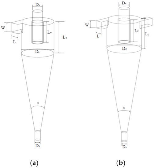
Figure 1.
Structure of the base hydrocyclones: (a) single inlet; (b) double inlet.

Table 1.
Basic dimensions of the hydrocyclones.
The oil-gas two-phase mixed flow enters the hydrocyclone with a certain velocity from the square inlet along the tangent direction of the cylindrical body, and the mixed flow changes from a straight-line motion to a strong rotary motion. Due to the density difference between oil and gas, the centrifugal force, the centripetal buoyancy force, and the fluid drag force of the two phases are different. The oil gathers at the wall of the hydrocyclone and the gas accumulates in the center of the hydrocyclone under the effect of the centrifugal force. Finally, the oil phase is discharged through the spigot of the hydrocyclone, and the gas phase is discharged from the vortex finder, so as to achieve the purpose of separation and classification.
2.2. Mathematical Model
In this study, ANSYS Fluent was used to simulate the oil–gas separation process. The mixture model was selected to simulate the oil–gas two-phase flow in the hydrocyclone. The oil is regarded as primary phase, and the gas is set as secondary phase. Several hypotheses are given as follows: (1) the oil is an incompressible fluid, = constant; (2) the gas is evenly distributed in the oil; (3) there is no mass exchange between the oil and gas; (4) the heat generated by the friction of fluid motion and the energy exchange with the outside world are ignored; and (5) the merger and rupture of bubbles are not considered.
The continuity equation for the mixture can be obtained as:
where is the average mass velocity, is the mixed density. These can be expressed as:
where and are the volume fraction of oil phase and gas phase, respectively, and are the density of oil phase and gas phase, respectively, and and are the velocity of oil phase and gas phase, respectively.
The momentum equation for the mixture is:
where is the volume force, is the viscosity of the mixed phase, and is the slip velocity of the gas phase. and can be expressed as:
The volume fraction equation of the second phase (i.e., gas) is:
During the existing turbulence model, the Reynolds stress model (RSM) can reveal many physical processes including the effects of turbulence anisotropy, particularly the rotation, buoyancy, and curvature effects. Therefore, the RSM was chosen as the turbulence model in this research.
The Reynolds transport equation [37] can be written as:
where is the diffusion term, is the shear stress generation term, is the buoyancy generation term, is the pressure strain, is the viscous discrete term, and is the rotary system generation term, which can be presented as:
Then the turbulent kinetic energy equation and turbulent energy dissipation rate equation can be described as:
The related parameters , , and defined by FLUENT are 0.15, 1.34, and 1.8, respectively.
2.3. Separation Performance Evaluation Index
The gas separation efficiency of the hydrocyclone is:
where is the volume flow rate of gas at the vortex finder and is the volume flow rate of gas at the square inlet.
The calculation formula of liquid loss rate is as follows:
where is the volume flow rate of liquid at the vortex finder and is the volume flow rate of liquid at the square inlet.
2.4. Grid Generation and Boundary Conditions
The three-dimensional physical models of the hydrocyclones were established by ANSYS-ICEM, and their grids were divided into structured grids. The grid models are shown in Figure 2.
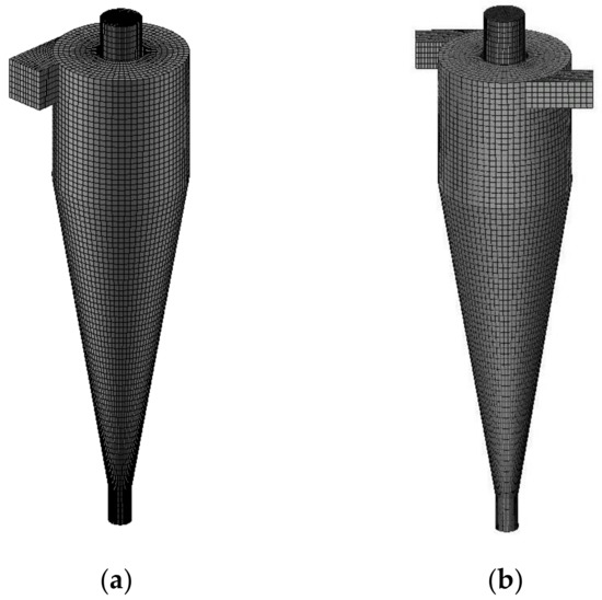
Figure 2.
Grid models of the hydrocyclones: (a) single inlet; (b) double inlet.
The mixture model is set as a multiphase model. The oil is the primary phase and the gas is the secondary phase. The density of oil is 972.2 kg/m3, and the viscosity is 1.48 mPa·s. The density of gas is 1.225 kg/m3, and the viscosity is 0.01834 mPa·s. The inlet of the hydrocyclone is set as the velocity inlet and the inlet velocity is 2.5 m/s. The velocity direction is perpendicular to the inlet interface and points to the inner side of the inlet. The two outlets of the hydrocyclone are set as the pressure outlet. The outlet pressure is set at atmospheric pressure, and both of outlets are not in direct contact with air. Considering the lubricating performance of the lubricating oil system, the gas content of the lubricating oil is assumed to be 30%.
A suitable grid is highly important for numerical simulation. To select the appropriate grid, it is necessary to test the grid independence. Table 2 lists the information for five different resolution grids. Figure 3 illustrates the comparison of static pressure drop with five different resolution grids. From the static pressure drop curve, it is evident that the static pressure drop increases slightly with the increase in grid number. The influence of grid resolution on static pressure drop decreases when the grid number exceeds 2, and the gap between grid 2 and grid 5 is only 2.55%. Figure 4 presents the comparison of gas separation efficiency and liquid loss rate under five different resolution grids. It can be observed that the trends of the gas separation efficiency curve and the static pressure drop curve are almost the same. Thus, it can be concluded that the static pressure drop can affect the gas separation efficiency, and the gas separation efficiency is increased with the static pressure drop. However, the static pressure drop has almost no effect on the liquid loss rate, because the liquid loss rate between grid 2 and grid 5 is only 0.69%. Considering the accuracy of the simulation results and calculation cost, grid 2 was chosen as the grid for the numerical simulation in this study.
Table 2.
Grid resolutions for the independence test.
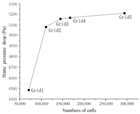
Figure 3.
Comparison of static pressure drop under five different resolution grids.
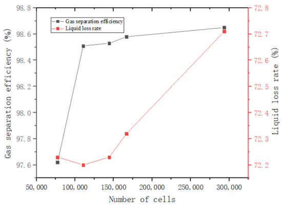
Figure 4.
Comparison of the gas separation efficiency and liquid loss rate under five different resolution grids.
3. Result Analysis and Discussion
3.1. Comparison of Single Inlet Hydrocyclone and Double Inlet Hydrocyclone
According to the oil–gas separation principle of the hydrocyclone, the lubricating oil can flow from the spigot as the gas discharges from the vortex finder due to the centrifugal effect. The centrifugal effect is enhanced as inlet velocity increases. Thus, the velocity of the gas gathering at the center is accelerated, which increases the efficiency of the gas separation. However, the liquid loss rate also increases. In addition, the radial pressure distribution produced by the swirling flow can also make the gas accumulate at the center and increase the oil–gas separation efficiency. In the presented research, the double inlet hydrocyclone was compared with the ordinary single inlet hydrocyclone under the conditions of the same velocity and flow rate.
Figure 5a shows the static pressure distribution curve at 60 mm from the top of the hydrocyclone. Figure 5a reveals that the pressure distribution of the double inlet hydrocyclone is axisymmetric, whereas the pressure distribution of the single inlet hydrocyclone is non-axisymmetric. For both types of hydrocyclones, the static pressure gradually decreases from the outer wall of the hydrocyclone to the central position of the hydrocyclone, and there is a minimum value at the central position. Figure 5b shows the distribution curve of tangential velocity at 60 mm from the top of the hydrocyclone. It can also be observed that the tangential velocity distribution of the double inlet hydrocyclone is more axisymmetric than that of the single inlet hydrocyclone, and the maximum value of tangential velocity appears at 11 mm from the central axis. By contrast, it is found that the tangential velocity of the double inlet hydrocyclone is greater than single inlet hydrocyclone, and the pressure drop of the double inlet hydrocyclone is greater than that of the single inlet hydrocyclone. This means that the double inlet hydrocyclone can improve the rotational speed and centrifugal effect of the fluid, and the symmetrical flow field is conducive to the gas gathering at the center of the hydrocyclone.
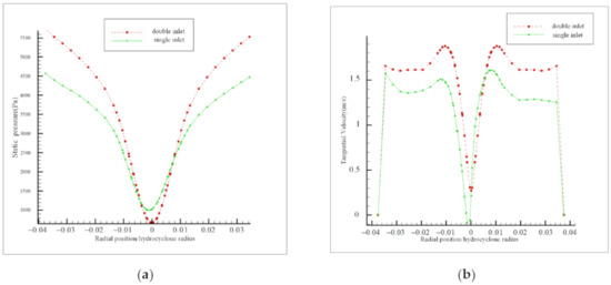
Figure 5.
Radial distribution at 60 mm from the top of the hydrocyclone: (a) static pressure; (b) tangential velocity.
Figure 6 shows the gas phase and static pressure distribution at the cross section of the hydrocyclone. It can be seen that the gas in the hydrocyclone gathers at the center due to the centrifugal effect, and most of the gas flows out from the vertex finder while a small amount flows out from the spigot. Figure 6a shows that a number of air vortexes are formed at the center of the single inlet hydrocyclone, and these air vortexes flow downward with the outer vortex, which makes the gas flow out from the spigot and reduces the gas separation efficiency. It can be seen from Figure 6a,c that the flow field of the single inlet hydrocyclone for oil–gas separation is more asymmetric than that of the ordinary single inlet hydrocyclone [17,27,30]. In the hydrocyclone for oil–gas separation, gas separation is a dynamic process, and there is no obvious boundary between gas and oil, so the fluid still exists in the form of a mixture. Furthermore, the vortex finder and the spigot are not in direct contact with the air, there is no air intake, and no air core can be formed. Therefore, the flow field was found to be asymmetric. Figure 6b shows the gas phase of the double inlet cyclone is mainly distributed in the cylindrical part, and a gaseous core is formed at the center of the hydrocyclone. There is a very small amount of gas discharges from the spigot. It was found that the gas separation efficiency of the double inlet hydrocyclone is 1.1% higher than that of the single inlet hydrocyclone. In addition, the double inlet swirling flow has a higher pressure drop and tangential velocity, which is conducive to gas aggregation at the center to enhance the gas separation effect. The double inlet hydrocyclone has related advantages in tangential velocity, pressure drop [38], and gas separation efficiency. The improvement of separation performance using a double inlet hydrocyclone was also reported by Nenu et al. [39] and Hwang et al. [40]. Thus, the double inlet hydrocyclone was selected as a preferable hydrocyclone in this research and used to investigate the oil–gas separation effect.
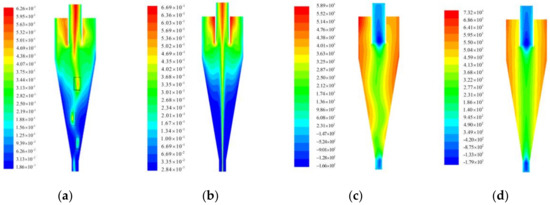
Figure 6.
Contours of the hydrocyclone: (a) gas phase distribution of single inlet hydrocyclone; (b) gas phase distribution of double inlet hydrocyclone; (c) static pressure distribution of single inlet hydrocyclone; (d) static pressure distribution of double inlet hydrocyclone.
3.2. Effect of the Vortex Finder Diameter
In contrast to the solid–liquid separation hydrocyclone, in which the separation performance is mainly determined by the cone section, the gas–liquid hydrocyclone separation is mainly determined by the cylindrical part [41]. Therefore, three structural parameters related to the cylindrical part, namely, the vortex finder diameter, the vortex finder length, and the cylindrical-part length, may have a significant influence on the gas–liquid separation properties.
To investigate the influence of vortex finder diameter on the oil–gas separation property, hydrocyclones with different vortex finder diameters of 15, 20, 25, 30, and 35 mm were designed. The established model was used to simulate the flow field characteristics and separation properties of the hydrocyclones under different diameter of vortex finder.
Figure 7a illustrates the radial static pressure distribution curve at 60 mm from the top of the hydrocyclone. It is shown that hydrocyclones under different vortex finder diameters have a pressure gradient. The maximum static pressure appears on the wall, and the static pressure gradually decreases from the wall to the central axis. As the vortex finder diameter increases, the fluid resistance decreases, the static pressure decreases, and the speed of the decrease along the radial falls. The hydrocyclones with vortex finder diameter of 30 and 35 mm form negative pressure at the center. Figure 7b shows the radial tangential velocity distribution curve at 60 mm from the top of the hydrocyclone, indicating that the distance between the position where the maximum tangential velocity occurs and the central axis is approximately equal to the vortex finder radius. With the increase in vortex finder diameter, the maximum tangential velocity decreases gradually. This means that the decrease in the vortex finder diameter can reduce the outlet area of the gas. In addition, the maximum tangential velocity increases with the increase in fluid resistance [42], which is conducive to improving the rotational speed and centrifugal effect of the fluid.
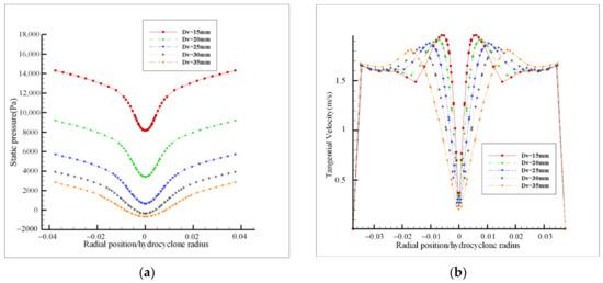
Figure 7.
Radial flow field distribution with different vortex finder diameters: (a) static pressure; (b) tangential velocity.
The curves of gas separation efficiency and liquid loss rate are plotted in Figure 8. As shown in Figure 8, both the gas separation efficiency and liquid loss rate increase with the increase in vortex finder diameter. When the vortex finder diameter exceeds 25 mm, the gas separation efficiency reaches 99%. Generally speaking, the hydrocyclones with five different vortex finder diameters have a certain oil–gas separation effect, and the gas separation rate does not increase with the increase in tangential velocity or pressure drop. Although the increase in tangential velocity and pressure drop is conducive to the improvement of separation efficiency, the increase in vortex finder diameter is conducive to the outflow of gas–liquid mixture from the top, which greatly reduces the separation resistance of the gas–liquid mixture from the vortex finder. The liquid loss curve rate shows that most of the liquid entrained with gas flows out from the vortex finder, which increases the gas separation efficiency and increases the liquid loss. When the diameter of the vortex finder is greater than 25 mm, the gas separation efficiency changes little, whereas the liquid loss rate changes greatly. Therefore, the 25 mm diameter of the vortex finder was found to be beneficial to the gas–liquid separation of the hydrocyclone.
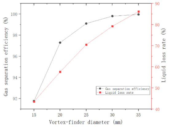
Figure 8.
Effect of the vortex finder diameter on the gas separation efficiency and liquid loss rate.
3.3. Effect of the Vortex Finder Length
When the gas–liquid two-phase flow enters the hydrocyclone, a part of the mixed liquid moves upward first and reaches the top of the hydrocyclone due to the friction resistance of the wall of the hydrocyclone. Then, the flow moves along the bottom of the top cover towards the central axis and moves downward along the outer wall of the vortex finder. Finally, it converges with the inner swirl and is discharged from the vortex finder. This flow form is the so-called short-circuit flow, which may cause the mixed flow to be discharged from the vortex finder without swirling separation. To study the effect of the vortex finder length on the oil–gas separation properties, five groups of hydrocyclones with different vortex finder lengths (20, 30, 40, 50 and 60 mm) were used for numerical simulation.
Figure 9 shows the radial pressure distribution curve (Figure 9a) and tangential velocity distribution curve (Figure 9b) at 70 mm from the top of hydrocyclone under different vortex finder lengths. Figure 9a shows that the pressure near the wall increases with the increase in the vortex finder length. However, the trend is opposite at 15 mm from the central axis. The pressure of the central part decreases with the increase in the vortex finder length. It can be concluded that the increase in the vortex finder length can help increase the pressure gradient of the flow field and provide better pressure conditions for gas separation. An interesting phenomenon can be noted from Figure 9b, namely, that there are two different curves with Lv = 50 mm as the dividing line. When the vortex finder length is equal to or exceeds 50 mm, the tangential velocity along the radial direction increases first and then decreases, and the distance between the position where the maximum tangential velocity occurs and the central axis is approximately equal to the vortex finder radius. When the vortex finder length is less than 50 mm, the tangential velocity decreases consistently from the wall to the central axis, which is smaller than that of the hydrocyclone with vortex finder lengths of 50 and 60 mm. The increase in the vortex finder length can help increase the tangential velocity of the hydrocyclone center. When Lv is greater than 50 mm, there is a peak of tangential velocity near the center of the hydrocyclone, which is beneficial to the separation of oil and gas at the center.
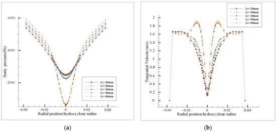
Figure 9.
Radial flow field distribution with different vortex finder lengths: (a) static pressure; (b) tangential velocity.
Figure 10 plots the curves of gas separation efficiency and liquid loss rate under different vortex finder lengths. It is evident in Figure 10 that the gas separation efficiency increases and the liquid loss rate decreases with the increase in the vortex finder length, indicating that the increase in the vortex finder length can help inhibit the short-circuit flow, which induces the mixed flow to be discharged from the vortex finder without swirling separation [28]. Thus, a longer vortex finder length is conducive to obtain a preferable gas separation efficiency considering the pressure gradient, the tangential velocity, and the liquid loss rate. However, the impact is relatively small.
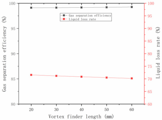
Figure 10.
Effect of the vortex finder length on the gas separation efficiency and liquid loss rate.
3.4. Effect of the Spigot Diameter
As the dense phase outlet of the hydrocyclone, the spigot is an important structural parameter because the spigot diameter can affect the split ratio. To study the influence of spigot diameter on the hydrocyclone properties, hydrocyclones with spigot diameters of 12.5, 20, 27.5, 35, and 42.5 mm were selected for study.
Analogous to the influence of vortex finder, the internal pressure gradually decreases with the increase in the spigot diameter due to the fact that a larger spigot diameter has a larger outlet area (as shown in Figure 11a). Considering the influence of spigot diameter and vortex finder diameter on the flow field, it can be concluded that reducing the outlet area can increase the internal pressure and increase the internal pressure gradient. Figure 11b shows the tangential velocity curve. With the increase in the spigot diameter, the tangential velocity decreases, and the maximum value of tangential velocity is obtained at the position equal to the vortex finder radius.
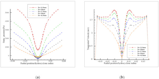
Figure 11.
Radial flow field distribution with different spigot diameters: (a) static pressure; (b) tangential velocity.
Figure 12 shows the curves of gas separation efficiency and liquid loss rate under different spigot diameters. As presented in Figure 12, with the increase in spigot diameter both gas separation efficiency and liquid loss rate decrease; in particular, the liquid loss rate decreases significantly. When the spigot diameter is 42.5 mm, only 20% of the liquid flows out from the vortex finder. Increasing the diameter of spigot is beneficial to the liquid flowing out from the spigot to reduce the liquid loss rate. However, the separated gas forms a larger gas center area in the center part of the hydrocyclone, and the gas outflow from the spigot increases, reducing the efficiency of gas separation. It also can be observed that as the spigot diameter exceeds 20 mm, the efficiency of gas separation decreases rapidly. Thus, this research indicates the spigot diameter should be about 20 mm.
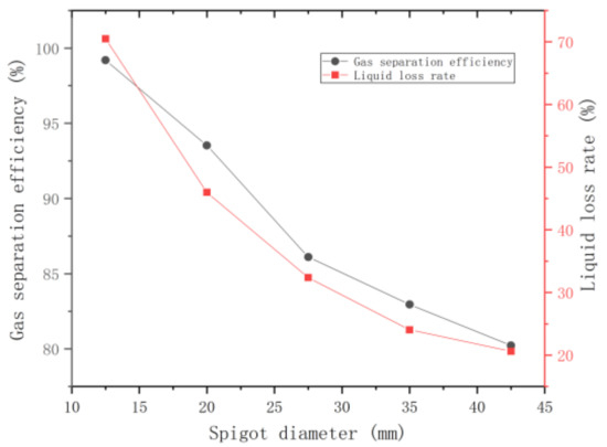
Figure 12.
Effect of the spigot diameter on the gas separation efficiency and liquid loss rate.
3.5. Effect of the Cylindrical-Part Length
The gas in the hydrocyclone is mainly concentrated in the cylindrical section. To reveal the effect of the cylindrical-part length on the separation of oil and gas in the hydrocyclone, the separation property of the hydrocyclone was studied under the cylindrical-part lengths of 65, 75, 85, 95, and 105 mm.
Figure 13 shows the radial pressure distribution curve (Figure 13a) and tangential velocity distribution curve (Figure 13b) at 60 mm from the top of the hydrocyclone under five different cylindrical-part lengths. As shown in Figure 13, the decrease in cylindrical-part length increases the pressure and tangential velocity. The difference of pressure and tangential velocity with different cylindrical-part lengths is small in the central area, whereas the difference is large near the wall.
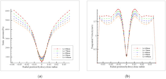
Figure 13.
Radial flow field distribution under different cylindrical-part lengths: (a) static pressure; (b) tangential velocity.
Figure 14 shows the curves of gas separation efficiency and liquid loss rate under different cylindrical-part lengths, indicating that with the increase in cylindrical-part length, the gas separation efficiency decreases and the liquid loss rate increases. When the cylindrical-part length increases, the tangential velocity and pressure drop decrease, and the gas gathering ability at the center is weakened, which reduces the gas separation efficiency. However, on the whole, the impact is relatively small.
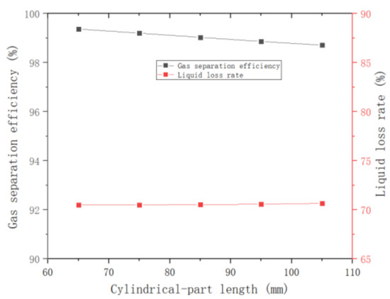
Figure 14.
Effect of the cylindrical-part length on the gas separation efficiency and liquid loss rate.
3.6. Effect of the Cone Angle
For hydrocyclones with the same diameter, the increase in the cone angle decreases the cone section and the separation time. To reveal the effect of cone angle on separation property, five types of hydrocyclones with cone angles of 17°, 19°, 21°, 23° and 25° were selected for simulation.
Figure 15 shows the radial pressure distribution curve (Figure 15a) and tangential velocity distribution curve (Figure 15b) at 60 mm from the top of the hydrocyclone under five different cone angles. As illustrated in Figure 15, the pressure distribution and tangential velocity curves of different cone angles are similar and have the same trend. When the cone angle increases, the pressure at the center of the cyclone decreases, the wall pressure increases, and the pressure difference increases. The increase in the cone angle can also increase the tangential velocity.
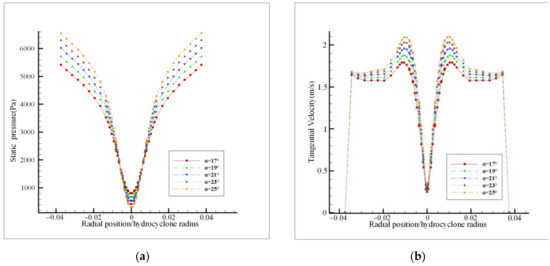
Figure 15.
Radial flow field distribution with different cone angles: (a) static pressure; (b) tangential velocity.
Figure 16 shows the curves of gas separation efficiency and liquid loss rate under different cone angles. As illustrated in Figure 16, with the increase in cone angle, the gas separation efficiency decreases and the liquid loss rate increases, and these trends are almost linear. Although the increase in cone angle can increase the pressure drop and tangential velocity, it shortens the length of the cone, reduces the separation time, and reduces the gas separation efficiency. However, the differences of gas separation efficiency and liquid loss rate under different cone angles are very small.
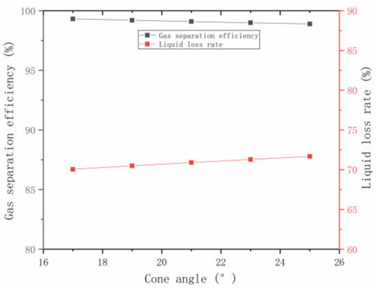
Figure 16.
Effect of the cone angle on the gas separation efficiency and liquid loss rate.
4. Conclusions
To eliminate the influence of gas in ships’ lubricating oil systems, a classic 75 mm hydrocyclone was studied as an oil–gas two-phase separation device. The influences of structural parameters of the hydrocyclone on the oil–gas separation properties were investigated using the CFD method to obtain a lubricant purification device with desirable performance.
The following can be concluded:
- (1)
- Because the vortex finder and the spigot of the hydrocyclone used in this study are not in direct contact with the air, no gas core forms. Moreover, there is no obvious boundary between oil and gas in the internal flow field, and the oil–gas two-phase distribution is uneven during the separation process. Therefore, the flow field in the single inlet hydrocyclone was found to be asymmetric. By contrast, for the double inlet hydrocyclone, the symmetrical inlet not only makes the flow field more symmetrical, but also provides higher pressure drop and tangential velocity. Additionally, the double inlet hydrocyclone achieves higher separation efficiency. This shows that the oil–gas separation performance of the double inlet hydrocyclone is better than that of the single inlet hydrocyclone.
- (2)
- The pressure drop and the maximum tangential velocity decrease as the vortex finder diameter increases. When the vortex finder diameter exceeds 25 mm, the gas separation efficiency changes little, whereas the liquid loss rate changes greatly. Thus, the vortex finder diameter should be chosen to be about 25 mm to obtain a preferable gas–liquid separation effect.
- (3)
- The pressure drop, tangential velocity, gas separation efficiency, and liquid loss rate decrease as the spigot diameter increases. However, when the spigot diameter exceeds 20 mm, the gas separation efficiency decreases rapidly. To ensure a preferable gas separation efficiency, the spigot diameter should be about 20 mm.
- (4)
- The vortex finder length, cylindrical-part length, and cone angle have little influence on the gas separation efficiency of the hydrocyclone.
Author Contributions
Y.L.: Conceptualization; Project administration; Writing—review & editing. J.W.: Formal analysis; Software. H.J.: Data curation; Methodology; Investigation; Writing—review & editing. O.L.: Investigation; Software; Writing—original draft. S.N.: Formal analysis; Investigation. All authors have read and agreed to the published version of the manuscript.
Funding
This research was funded by the CSIC Key Laboratory of Thermal Power Technology Open Foundation (Grant No. TPL2017BB010), and Beijing Municipal Science and Technology Project (Grant Nos. KM201910005033 and KM201810005014) for their funding for this research.
Acknowledgments
The authors are very grateful to the editors and the anonymous reviewers for their insightful comments and suggestions.
Conflicts of Interest
The authors declare no conflict of interest.
References
- Hong, N. The melting Arctic and its impact on China’s maritime transport. Res. Transp. Econ. 2012, 35, 50–57. [Google Scholar] [CrossRef]
- Arendt, R. The application of an expert system for simulation investigations in the aided design of ship power systems automation. Expert Syst. Appl. 2004, 27, 493–499. [Google Scholar] [CrossRef]
- Nguyen, H. The application of the ahp method in ship system risk estimation. Pol. Marit. Res. 2009, 16, 78–82. [Google Scholar] [CrossRef][Green Version]
- Anantharaman, M. Using Reliability Block Diagrams and Fault Tree circuits, to develop a Condition Based Maintenance Model for a Vessel’s Main Propulsion System and Related Subsystems. TransNav Int. J. Mar. Navig. Saf. Sea Transp. 2013, 7, 409–413. [Google Scholar] [CrossRef][Green Version]
- Chengtao, C.; Chuanbin, Z.; Gang, L. A novel fault diagnosis approach combining SVM with association rule mining for ship diesel engine. In Proceedings of the 2016 IEEE International Conference on Information and Automation (ICIA), Ningbo, China, 1–3 August 2016; pp. 130–135. [Google Scholar]
- He, Q.; Chen, G.; Chen, X.; Yao, C. Application of oil analysis to the condition monitoring of large engineering machinery. In Proceedings of the 8th International Conference on Reliability, Maintainability and Safety, Chengdu, China, 20–24 July 2009; pp. 1100–1103. [Google Scholar]
- Tahan, M.; Tsoutsanis, E.; Muhammad, M.; Karim, Z.A. Performance-based health monitoring, diagnostics and prognostics for condition-based maintenance of gas turbines: A review. Appl. Energy 2017, 198, 122–144. [Google Scholar] [CrossRef]
- Sharma, B.; Gandhi, O. Performance evaluation and analysis of lubricating oil using parameter profile approach. Ind. Lubr. Tribol. 2008, 60, 131–137. [Google Scholar] [CrossRef]
- Bradley, D. The Hydrocyclone; Pergamon Press: London, UK, 1965. [Google Scholar]
- Ni, L.; Tian, J.; Zhao, J. Feasibility of a novel de-foulant hydrocyclone with reflux for flushing away foulant continuously. Appl. Therm. Eng. 2016, 103, 695–704. [Google Scholar] [CrossRef]
- Bayo, J.; López-Castellanos, J.; Martínez-García, R.; Alcolea, A.; Lardín, C. Hydrocyclone as a cleaning device for anaerobic sludge digesters in a wastewater treatment plant. J. Clean. Prod. 2015, 87, 550–557. [Google Scholar] [CrossRef]
- Shin, M.-S.; Kim, H.-S.; Jang, D.-S.; Chung, J.-D.; Bohnet, M. A numerical and experimental study on a high efficiency cyclone dust separator for high temperature and pressurized environments. Appl. Therm. Eng. 2005, 25, 1821–1835. [Google Scholar] [CrossRef]
- Lee, H.; Park, J.; Lee, J.-C.; Ko, K.; Seo, Y. Development of a hydrocyclone for ultra-low flow rates. Chem. Eng. Res. Des. 2020, 156, 100–107. [Google Scholar] [CrossRef]
- Pratarn, W.; Tanthapanichakoon, W.; Yoshida, H. Classification of silica fine particles using a novel electric hydrocyclone. Sci. Technol. Adv. Mater. 2005, 6, 364–369. [Google Scholar] [CrossRef]
- Lim, E.W.C.; Chen, Y.-R.; Wang, C.-H.; Wu, R.-M. Experimental and computational studies of multiphase hydrodynamics in a hydrocyclone separator system. Chem. Eng. Sci. 2010, 65, 6415–6424. [Google Scholar] [CrossRef]
- Zhen-Bo, W.; Yi, M.; You-Hai, J. Simulation and experiment of flow field in axial-flow hydrocyclone. Chem. Eng. Res. Des. 2011, 89, 603–610. [Google Scholar] [CrossRef]
- Swain, S.; Mohanty, S. A 3-dimensional Eulerian–Eulerian CFD simulation of a hydrocyclone. Appl. Math. Model. 2013, 37, 2921–2932. [Google Scholar] [CrossRef]
- Kępa, A. The efficiency improvement of a large-diameter cyclone—The CFD calculations. Sep. Purif. Technol. 2013, 118, 105–111. [Google Scholar] [CrossRef]
- Marthinussen, S.-A.; Chang, Y.-F.; Balakin, B.; Hoffmann, A.C. Removal of particles from highly viscous liquids with hydrocyclones. Chem. Eng. Sci. 2014, 108, 169–175. [Google Scholar] [CrossRef]
- Zhang, C.; Wei, D.; Cui, B.; Li, T.; Luo, N. Effects of curvature radius on separation behaviors of the hydrocyclone with a tangent-circle inlet. Powder Technol. 2017, 305, 156–165. [Google Scholar] [CrossRef]
- Hwang, K.-J.; Chou, S.-P. Designing vortex finder structure for improving the particle separation efficiency of a hydrocyclone. Sep. Purif. Technol. 2017, 172, 76–84. [Google Scholar] [CrossRef]
- Ji, L.; Kuang, S.; Qi, Z.; Wang, Y.; Chen, J.; Yu, A. Computational analysis and optimization of hydrocyclone size to mitigate adverse effect of particle density. Sep. Purif. Technol. 2017, 174, 251–263. [Google Scholar] [CrossRef]
- Silva, N.K.; Silva, D.O.; Vieira, L.G.; Barrozo, M.A.S. Effects of underflow diameter and vortex finder length on the performance of a newly designed filtering hydrocyclone. Powder Technol. 2015, 286, 305–310. [Google Scholar] [CrossRef]
- Mokni, I.; Dhaouadi, H.; Bournot, P.; Mhiri, H. Numerical investigation of the effect of the cylindrical height on separation performances of uniflow hydrocyclone. Chem. Eng. Sci. 2015, 122, 500–513. [Google Scholar] [CrossRef]
- Vakamalla, T.R.; Kumbhar, K.S.; Gujjula, R.; Mangadoddy, N. Computational and experimental study of the effect of inclination on hydrocyclone performance. Sep. Purif. Technol. 2014, 138, 104–117. [Google Scholar] [CrossRef]
- Ghodrat, M.; Kuang, S.; Yu, A.; Vince, A.; Barnett, G.; Barnett, P. Numerical analysis of hydrocyclones with different vortex finder configurations. Miner. Eng. 2014, 63, 125–138. [Google Scholar] [CrossRef]
- Kyriakidis, Y.N.; Silva, D.O.; Barrozo, M.A.S.; Vieira, L.G.M. Effect of variables related to the separation performance of a hydrocyclone with unprecedented geometric relationships. Powder Technol. 2018, 338, 645–653. [Google Scholar] [CrossRef]
- Ji, H.; Nie, S.-L.; Sun, H.; Cheng, Y.; Li, Y. Effects of key structural parameters on solid–liquid separation behavior of hydrocyclone separator applied to hydraulic oil purification. Proc. Inst. Mech. Eng. Part E J. Process. Mech. Eng. 2012, 227, 273–286. [Google Scholar] [CrossRef]
- Quian, L.; Changlie, D.; Jirun, X.; Lixin, Y.; Guangai, X. Comparison of the performance of water-sealed and commercial hydrocyclones. Int. J. Miner. Process. 1989, 25, 297–310. [Google Scholar] [CrossRef]
- Evans, W.K.; Suksangpanomrung, A.; Nowakowski, A.F. The simulation of the flow within a hydrocyclone operating with an air core and with an inserted metal rod. Chem. Eng. J. 2008, 143, 51–61. [Google Scholar] [CrossRef]
- Sripriya, R.; Kaulaskar, M.; Chakraborty, S.; Meikap, B. Studies on the performance of a hydrocyclone and modeling for flow characterization in presence and absence of air core. Chem. Eng. Sci. 2007, 62, 6391–6402. [Google Scholar] [CrossRef]
- Movafaghian, S.; Jaua-Marturet, J.; Mohan, R.; Shoham, O.; Kouba, G. The effects of geometry, fluid properties and pressure on the hydrodynamics of gas–liquid cylindrical cyclone separators. Int. J. Multiph. Flow 2000, 26, 999–1018. [Google Scholar] [CrossRef]
- Hreiz, R.; Lainé, R.; Wu, J.; Lemaitre, C.; Gentric, C.; Fuenfschilling, D. On the effect of the nozzle design on the performances of gas–liquid cylindrical cyclone separators. Int. J. Multiph. Flow 2014, 58, 15–26. [Google Scholar] [CrossRef]
- Zeng, X.; Fan, G.; Xu, J.; Liu, A.; Xu, Y.; Yan, C. Experimental study on a new gas–liquid separator for a wide range of gas volume fraction. Chem. Eng. Res. Des. 2020, 160, 561–570. [Google Scholar] [CrossRef]
- Noor, S.; Soliman, H. Experimental assessment of a new device for gas–liquid separation. Chem. Eng. Res. Des. 2019, 149, 45–51. [Google Scholar] [CrossRef]
- Xu, X.; Yang, Q.; Wang, C.-Y.; Ge, X.-L.; Wang, H.-L. Dissolved gas separation using the pressure drop and centrifugal characteristics of an inner cone hydrocyclone. Sep. Purif. Technol. 2016, 161, 121–128. [Google Scholar] [CrossRef]
- Jiang, L.; Liu, P.; Yang, X.; Zhang, Y.; Wang, H.; Xu, C. Numerical analysis of flow field and separation characteristics in hydrocyclones with adjustable apex. Powder Technol. 2019, 356, 941–956. [Google Scholar] [CrossRef]
- Li, F.; Liu, P.; Yang, X.; Zhang, Y. Numerical simulation on the effects of different inlet pipe structures on the flow field and seperation performance in a hydrocyclone. Powder Technol. 2020, 373, 254–266. [Google Scholar] [CrossRef]
- Nenu, R.K.T.; Yoshida, H. Comparison of separation performance between single and two inlets hydrocyclones. Adv. Powder Technol. 2009, 20, 195–202. [Google Scholar] [CrossRef]
- Hwang, K.J.; Hwang, Y.W.; Yoshida, H. Design of novel hydrocyclone for improving fine particle separation using computational fluid dynamics. Chem. Eng. Sci. 2013, 85, 62–68. [Google Scholar] [CrossRef]
- Ye, J.; Xu, Y.; Song, X.; Yu, J. Numerical modelling and multi-objective optimization of the novel hydrocyclone for ultra-fine particles classification. Chem. Eng. Sci. 2019, 207, 1072–1084. [Google Scholar] [CrossRef]
- Elsayed, K.; Lacor, C. The effect of cyclone vortex finder dimensions on the flow pattern and performance using LES. Comput. Fluids 2013, 71, 224–239. [Google Scholar] [CrossRef]


Publisher’s Note: MDPI stays neutral with regard to jurisdictional claims in published maps and institutional affiliations. |
© 2020 by the authors. Licensee MDPI, Basel, Switzerland. This article is an open access article distributed under the terms and conditions of the Creative Commons Attribution (CC BY) license (http://creativecommons.org/licenses/by/4.0/).