Article

Experimental Study on the Flow and Heat Transfer of Graphene-Based Lubricants in a Horizontal Tube

School of Energy and Power Engineering, Shandong University, Jinan 250061, China
*
Author to whom correspondence should be addressed.
Processes 2020, 8(12), 1675; https://doi.org/10.3390/pr8121675
Submission received: 16 October 2020 / Revised: 6 December 2020 / Accepted: 14 December 2020 / Published: 18 December 2020

Abstract

:
To improve the heat transfer characteristics of lubricant, graphene-based lubricants were prepared by adding graphene particles, due to its advantages of excellent thermal conductivity and two-dimensional sheet structure. In the present study, its physical properties were measured. A flow heat transfer experiment platform was built to study the flow and heat transfer characteristics of the graphene lubricating oil in a horizontal circular tube. The results show that the graphene lubricant prepared using a two-step approach had good stability, and the dispersibility was good without the agglomeration phenomenon, according to measurements undertaken using an electron microscope and centrifuge. The thermal conductivity and viscosity of graphene lubricant increased with the increase of the graphene concentration, and the thermal conductivity of graphene lubricant with the same concentration decreased with the increase of temperature. When the concentration was equal, the convective heat transfer Nusselt number (Nu) of graphene lubricant increased with the increase of Reynolds number (Re). When Re was equal, the convective heat transfer Nu increased with the increase of graphene particle concentration, and the maximum Nu increased by 40%.

1. Introduction

The internal combustion engine is a power source of vehicles. It converts the thermal energy released from the combustion of fuels into mechanical energy that drives the vehicles. The safe running of vehicles greatly depends on the operational reliability of the internal combustion engine. As an important friction pair, the thermal load and lubrication friction status of the piston set–cylinder liner directly influence the reliability and durability of the internal combustion engine. This plays a decisive role in power performance, economical efficiency, and safe operation of the internal combustion engine. The operating conditions of the piston set–cylinder liner are severe, and include high temperature, high pressure, and high impact load. The circulating and transient high-temperature and high-pressure gas exposes the piston set–cylinder liner to a significant heat load. If the temperature of the heated parts in an internal combustion engine is too high, the hardness and strength of the material will decrease sharply, thus possibly resulting in ablation and deformation of heated parts. In addition, the lubricating oil film may be destroyed or even coked, causing serious abrasion and failure. Therefore, addressing the problems of heat transfer and lubrication friction of the piston set–cylinder liner is a popular research topic that has received considerable attention [1,2,3]. Vianna [4] researched the influence of the change of lubricant thermal conductivity on engine heat flow, and it was found that the thermal conductivity was improved by 20% after using a lubricant with high thermal conductivity, and the overall temperature and heat transfer rate of the engine were increased by 5% for the given cylindrical geometry and engine operating conditions.
In 1995, S. Choi [5] first proposed the concept of “nanofluid”, referring to dispersing nano-level (<100 nm) metal or oxide particles in a base solution, with a certain proportion and mode, to achieve a series of new heat transfer and cooling working media. Thermal scattering due to chaotic motion of nanoparticles increased the energy exchange in the medium. A large number of studies have shown that nanofluid has high thermal conductivity [6,7,8] and excellent convective heat transfer [9,10,11,12,13]. The research of Heris et al. [11] found that the convective heat transfer coefficient of nanofluid increased with the increase of volume concentration of nanoparticles. It was also found that the convective heat transfer coefficient of CuO nanofluid was lower than that of Al2O3 nanofluid, which may be related to the viscosity of nanofluids and the size of nanoparticles.
Graphene is a typical carbon allotrope with a two-dimensional crystal structure [14,15], and this kind of special structure endows graphene with excellent electrical [16], thermal [17], and mechanical properties [18]. Due to its development, an increasing amount of attention has been paid to graphene. Therefore, researchers have investigated heat transfer mechanisms from different perspectives for graphene nanofluids. Baby et al. [19] prepared relevant nanofluid by dispersing graphene into deionized water and glycol. The experimental test found that the thermal conductivity of deionized water nanofluids with a volume fraction of 0.05% at 20 °C can be enhanced by about 16%, but when the temperature was increased to 50 °C, it can be enhanced by 75%. Meanwhile, the increase of Nu was more obvious than that of thermal conductivity for convective heat transfer. Ma et al. [20] prepared graphene nanofluids with functionalization using a two-step approach and the thermal conductivity was measured. When the mass fraction of graphene was 0.07% and the nanofluid temperature was 20 °C, the thermal conductivity was increased by 5.74%. When the temperature reached 60 °C, the thermal conductivity was increased by about 18.9%. Hajjar et al. [21] explored the relationship of graphene concentration and temperature on thermal conductivity in uniformly dispersed graphene nanofluids. The thermal conductivity of graphene nanofluids was significantly improved compared to the basic lubricant. Moreover, it was related to the concentration of graphene and the temperature of the fluid. When the mass concentration of graphene was 0.25%, the temperature increased from 20 to 40 °C, and the thermal conductivity increased from 33.9% to 47.5%. When the temperature was 40 °C, and the mass concentration of graphene increases from 0.05% to 0.25%, the thermal conductivity increases from 14.7% to 47.5%. Therefore, regardless of the nanoparticles added to the lubricant, they can increase thermal conductivity and the convective heat transfer coefficient from the perspective of heat transfer. Researchers believe this is caused by Brownian motion, the boundary layer between the surface of nanoparticles and the solution, and the particle aggregation in the solution and phonon transfer [22].
Graphene nanoparticles have become potential high-performance lubricating materials with excellent thermal conductivity, antifriction, and anti-wear properties, in addition to chemical inertness, which can obviously improve the heat transfer characteristics of lubricants. However, research on the heat transfer characteristics of graphene lubricants requires further exploration. In this study, we prepared graphene lubricant nanofluids and physical properties were tested. Furthermore, an experimental platform was built to study the flow and heat transfer characteristics in a horizontal round tube.

2. Materials and Physical Properties

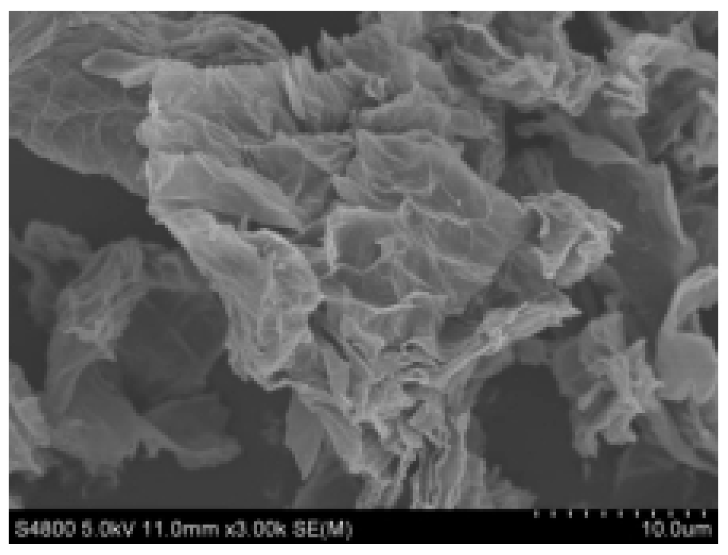
2.1. Graphene Material

The graphene used in the experiment is N002-PDR reduced graphene (The Sixth Element (Changzhou) Material Technology Co., Ltd. (Changzhou, Jiangsu, China)), and the physical parameters are shown in Table 1.
To better observe the surface morphology of graphene, an SEM (HITACHI-S4800) was used to conduct the tests (Figure 1). Figure 1 shows that it has a uniform lamellar structure, and the number of layers can be seen from the transparency degree.

2.2. Graphene Lubricant

A two-step approach was adopted to prepare the graphene lubricant nanofluids. Firstly, lipophilic polymers containing graphene affinity groups was dispersed in the lubricant through magnetic stirring, and graphene powders with different qualities were weighed to be added to a base solution containing dispersant to conduct stirring and an ultrasonic water bath. Graphene lubricant nanofluids were prepared with mass fractions of 0.5%, 1%, 2%, and 3%. The base oil used in the experiment was heavy duty diesel engine oil CH-4 20W-50. The dispersant “lipophilic polymer” was WinSperse 6020, which has a chemical composition of a non-polar polymer with amino affinity groups and an amine number (mgKOH/g) of 42–52.

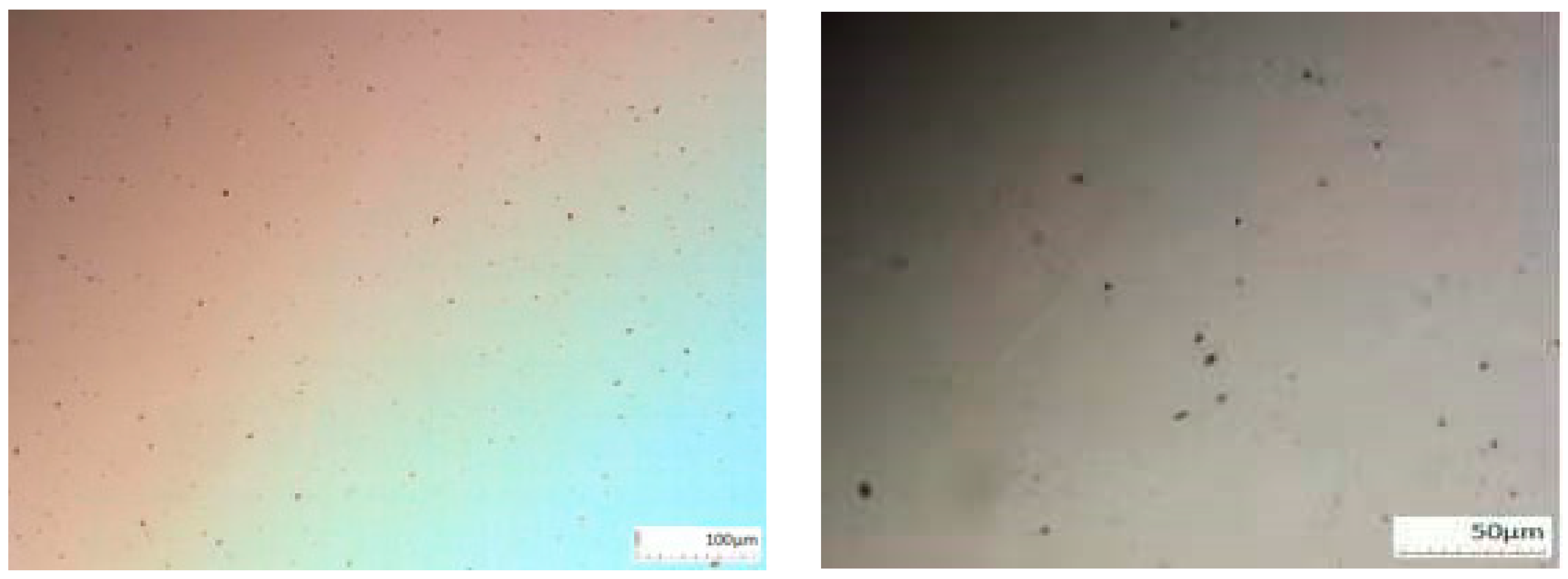
2.2.1. Micro-Characteristic Test

Graphene was dispersed into lubricant. If the dispersion method and dispersant are not suitable, this can readily result in the problem of agglomeration. Therefore, to better characterize the dispersion of graphene lubricant, the lubricant was placed under an multifunctional stereomicroscope (OM, Olympus, Tokyo, Japan) to conduct sample morphology observation (Figure 2). It could be seen that graphene existed uniformly in the solution with a lamellar structure, with a grain transverse dimension of 2–3 µm without agglomeration.

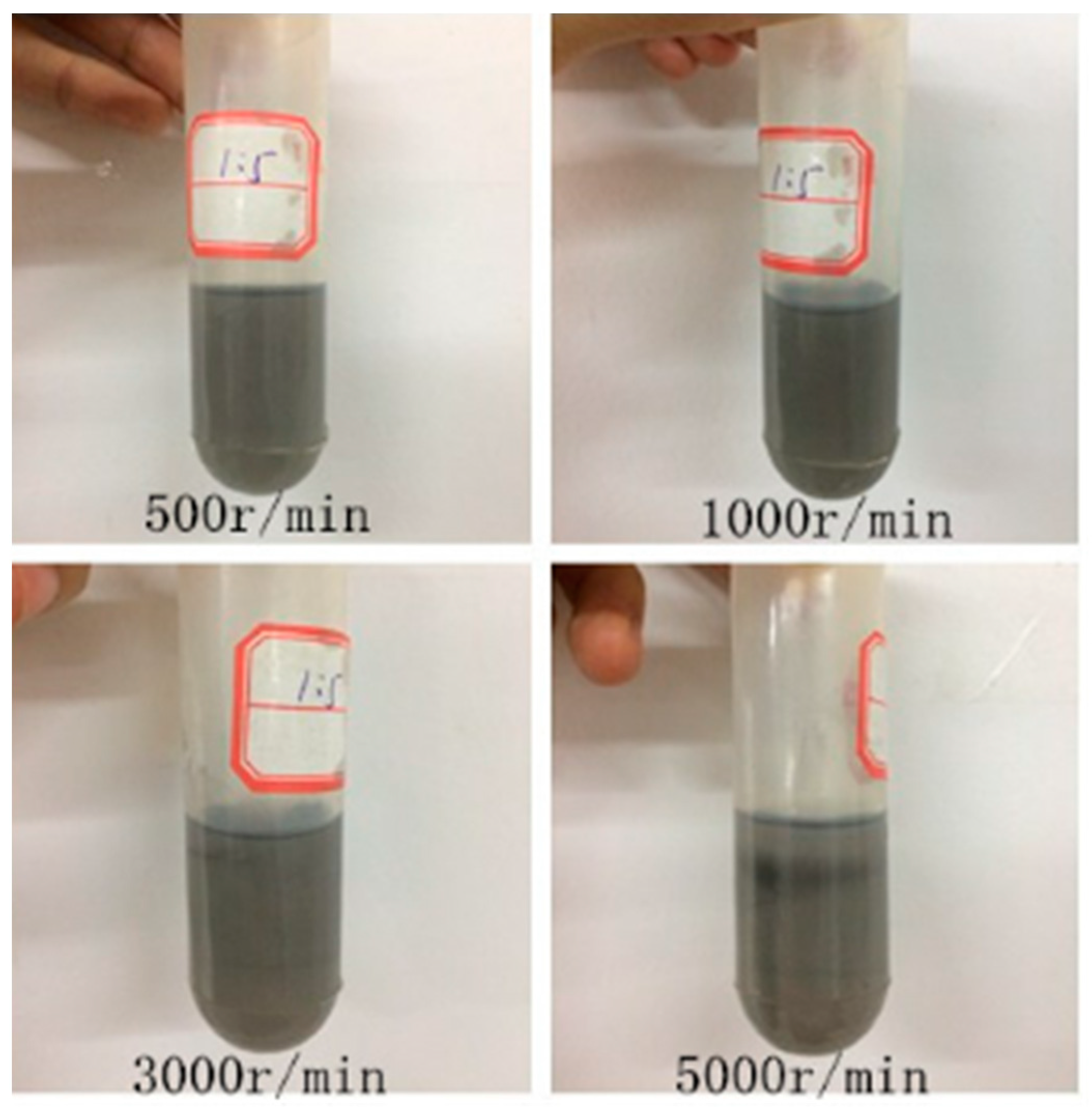
2.2.2. Stability Test

In the process of long-term use, it is difficult for the prepared graphene nanofluids to exist stably due to the existence of various interaction forces between particles, and between the suspended nanoparticles and the surrounding base fluid. The interfacial thermal resistance between nanoparticles and the base fluid increases due to particle aggregation, which influences the heat transfer among particles and greatly influences thermal properties. To test the dispersion stability of the prepared graphene lubricant, a high-speed centrifuge was used with speeds of 500, 1000, 3000, and 5000 r/min to test the stability of the 3% graphene lubricant for 30 min. It was found that there was no obvious particle aggregation or precipitation in the graphene lubricant, and the lubricant had better dispersion stability (Figure 3).

2.2.3. Thermal Conductivity Test

A thermal constant analyzer (Hot Disk TPS2500, manufacturer: Hot Disk AB, Goteborg, Sweden), based on the transient plane source method, was adopted to measure the thermal conductivity of the prepared graphene lubricant. To ensure measurement accuracy, the analyzer should be maintained for at least 20 minutes before measurement to ensure that the water bath and the measured nanofluid reach thermal equilibrium. Figure 4 shows results of thermal conductivity of nanofluids at a temperature of 20 °C with different mass fractions (0%, 0.5%, 1%, 2%, 3%). It can be seen from the figure that the thermal conductivity increased with the increase of mass fraction, and the thermal conductivity of nano-graphene lubricant with different fractions of 0.5%, 1%, 2%, and 3% increased by 1.02%, 1.69%, 14.81%, and 23.06%, respectively, compared to the base lubricant. This is because, with the increase of mass concentration, the number of graphene particles in a unit mass of graphene lubricant increases, and the probability of collision between the particles increases, which enhances the heat transfer and micro-convection between the particles and the base solution. Figure 5 shows the thermal conductivity and temperature of graphene lubricant. It can be seen from the graph that, when the temperature rises, the thermal conductivity of the base solution decreases. From 0.1661 at 20 °C to 0.1602 at 70 °C, the decrease was 3.69%. When graphene nanofluids were added to the lubricant, the thermal conductivity decreased with the increase of temperature, and with the increase of mass concentration, the decline increased. The thermal conductivity of nano-graphene lubricants with mass concentrations of 0.5%, 1%, 2%, and 3% achieved declines of 1.33%, 4.45%, 6.07%, and 7.62%, respectively, from 20 to 70 °C. This occurred because, when the temperature rises, due to the molecular association, graphene nanofluids exhibit the same properties as lubricants. In addition, the reduced rate of thermal conductivity was more obvious with the increase of concentration caused by the molecular association.

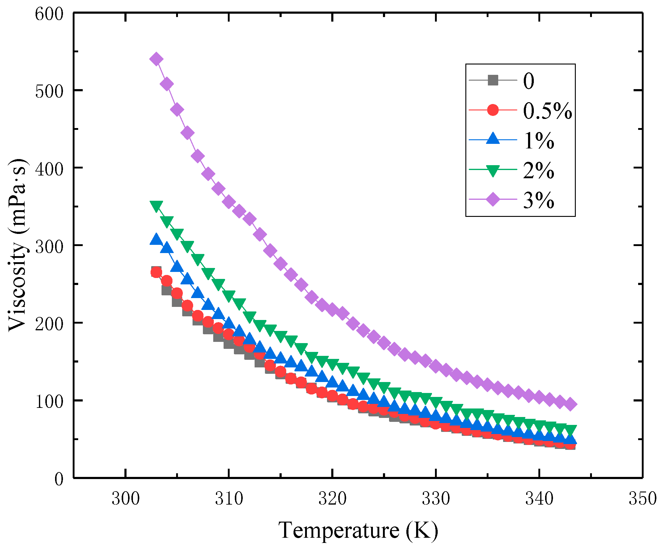
2.2.4. Viscosity Test

In the process of fluid flow and heat transfer, viscosity is a highly important parameter of thermophysical properties, and can directly influence the pumping power of nanofluids in flow and heat transfer. Thus, viscosity measurements were undertaken of mass transfer efficiency for graphene nanofluids at different temperatures using a rotary viscometer (model: DV-Ⅱpro, manufacturer: Bookfield, Middleboro, MA, USA). Figure 6 shows the variation of viscosity with the temperature of graphene lubricant at 303–343 K with mass fractions of 0%, 0.5%, 1%, 2%, and 3%. Figure 6 shows the viscosity of lubricating oil graphene nanofluids at different measurement temperatures. It can be seen from the figure that the viscosity of lubricating oil increases with the addition of graphene nanoparticles. This is because, with the increase of the mass fraction of nanoparticles, the number of nanoparticles per unit mass increases, which increases the shear effect of nanofluids. The viscosity of the nanofluid decreases with the increase of temperature, which is mainly because the Brownian motion of molecules becomes more intense with the increase of temperature, which weakens the adhesion effect between molecules and between particles.
For the relationship between viscosity and the temperature of lubricating oil, the following equation was established according to the experimental data:
v = A e ( T / B ) + C
The coefficients in the equation and viscosity index are listed in Table 2.

2.2.5. Specific Heat Capacity Test

Differential Scanning Calorimeter was used (model: DSC25 manufacturer: TA Instruments, New Castle, DE, USA) to measure the specific heat capacity of graphene lubricants with different temperatures and concentrations. Figure 7 shows that within the experimental temperature range, the specific heat capacity of the lubricant increased with the increase of temperature. At the same temperature, the specific heat capacity of the nano-graphene lubricant was larger than that of the base lubricant, and increased with the increase of graphene concentration. At a temperature of 8353 K, the growth rates of the heat capacity of the graphene lubricant with different mass concentrations of 0.5%, 1%, 2%, and 3% were 1.7%, 3.2%, 3.4%, and 4.4%, respectively, compared with the base lubricant.

3. Experimental Study on Flow and Heat Transfer

3.1. Experimental System

Figure 8 shows the flow and heat transfer experimental system of graphene lubricant in a horizontal round tube. The system is an open flow circulation system. It mainly comprises an oil tank, low temperature constant temperature bath (model: DS-0506 company: Shanghai Doosi Instrument Co., Ltd., Shanghai, China), micro-gear pump (model: WT3000-1FB company: Longer Constant Flow Pump Co., Ltd., Baodin, China), experimental section of flow and heat transfer performance, contact voltage regulator (Zhejiang Delixi Electric Appliance Co., Ltd., Leqing, China), and data acquisition instrument (model: 34970A company: Agilengt, Santa Clara, CA, USA). The experimental section of flow and heat transfer performance was the core component, which was made of copper tube with length of 2.8 m, internal diameter of 5 mm, and wall thickness of 0.5 mm; 17 thermocouples were installed for temperature measurement. Among these, two thermocouples were inserted into the inlet and outlet pipes for the measurement of inlet and outlet fluid temperature, respectively, and the other 15 thermocouples were uniformly soldered along the axial direction of the pipe, which was connected to the outer wall of the copper pipe with a copper hoop for the measurement for the changes of wall temperature along the axial direction. In addition, two pressure transmitters were arranged at the inlet and outlet of the pipeline to measure the pressure of the inlet and outlet fluids. The resistance tape was evenly wound around the outside tube (power 600 W) to heat the fluid in the tube, to achieve constant heat flux boundary conditions. To prevent electrical leakage of the electric resistance belt and eliminate heat dissipation to the environment, glass ribbon and insulation material were twined around the outside of copper tube.
During the experiment, the temperature of the water bath in the constant temperature water bath should first be adjusted. The temperature of the nanofluid at the entrance of the experimental section was ensured to be constant via the heat transfer between the coil and the fluid in the installed oil tank. The fluid was sucked out of the reservoir by a micro gear pump to conduct flow and heat transfer experiments after entering the experimental section. The power supply of the electric heating belt was connected, and can regulate the voltage of the electric heating belt to control the electric heating power via a contacting voltage regulator. The heating power of the experimental section was measured by a high-precision power meter. The inlet temperature of the experimental fluid was about 50 °C. The convective heat transfer characteristics of graphene lubricant with mass fractions of lubricant and graphene of 0.5%, 1%, 2%, and 3% were measured at the flow rate of 0.08–0.70 m/s. To ensure the accuracy of measurement data, the data were recorded after the heat transfer experiment was stable for 30 min, and the average of experimental data within 10 min was taken as the experimental data.

3.2. Experimental Data Treatment

Nu represents the dimensionless excess temperature gradient in the normal direction of the wall, which reflects the strength of convective heat transfer
N u = h D λ
D is the equivalent diameter of the channel.
Re is the Reynolds number of the nanofluids. It represents the relative magnitude of inertia force and viscosity force in fluid flow
R e = u D v
U is the average flow velocity of the nanofluids.
The temperature measured by 15 thermocouples placed on the outer wall of the pipe was calculated, and arithmetic mean and the average temperature Tw of the tube outer wall was obtained:
T w = i = 1 15 T i 15
Average temperature of fluid Tf:
T f = T i n + T o u t 2
The heating power was calculated from the supply voltage U and current I, close to the output power P of the power supply:
P = UI
Heat carried away by fluid q:
q = m c p ( T o u t T i n )
where Tin is the fluid inlet temperature (°C); Tout is the fluid outlet temperature (°C); cp is the specific heat capacity of the fluid (kJ/(kg·°C)and m is the fluid mass flow rate (kg/s).
The experiment was carried out under steady conditions, and the round tube was treated as a one-dimensional steady state heat conduction under the situation of no axial heat loss on the tube wall. The governing equations and boundary conditions are as follows:
d d r ( r d t d r ) = 0
λ d t d r | r = r 2 = U I 2 π λ L ln r 2 r 1
According to the integral of the above equation, the temperature difference between the inner and outer wall of the copper tube can be obtained as follows:
T w 2 T w 1 = U I 2 π λ L ln r 2 r 1
The formula for the average convective heat transfer coefficient of the fluid in the tube can be obtained as:
h = q A Δ T = U I 2 π r 1 L ( T w 1 T f )
where r1 is the inner radius of round tube, r2 is the outer radius of round tube, L is the pipe length, Tw1 is the temperature of inner wall of round tube, Tw2 is the outer radius of outer wall of round tube, and λ is the thermal conductivity of tube wall material.

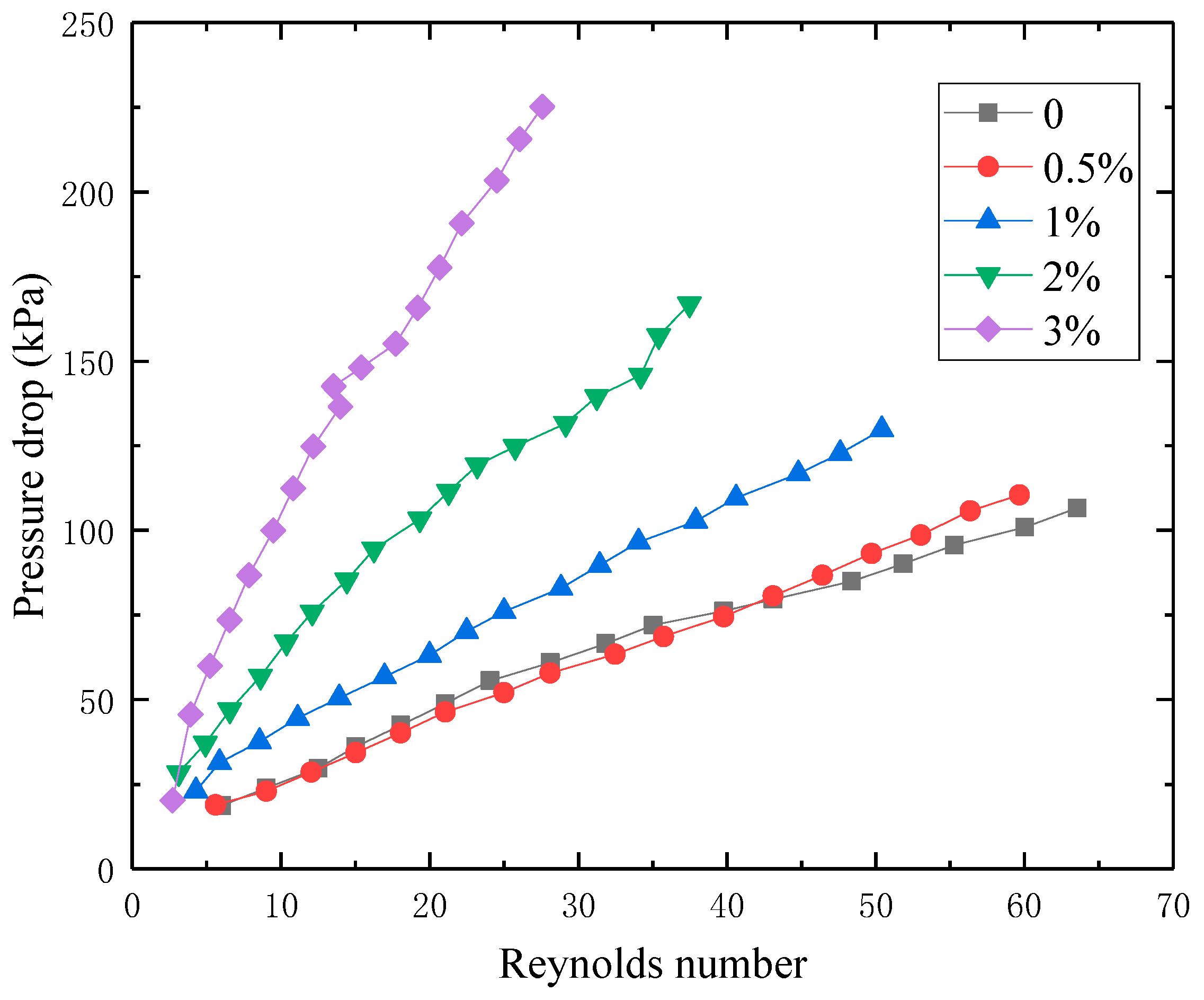
3.3. Pressure Drop Characteristics

Figure 9 shows the relationship between the variation of pressure drop and flow Re for graphene lubricant with different mass concentrations flowing in a horizontal round tube. It can be seen from the figure that when graphene particles were added to the lubricant, the pressure drop was higher than that of the common lubricant. In the same manner as for the common lubricant, it increased with the increase in flow Re, with a linear relationship.

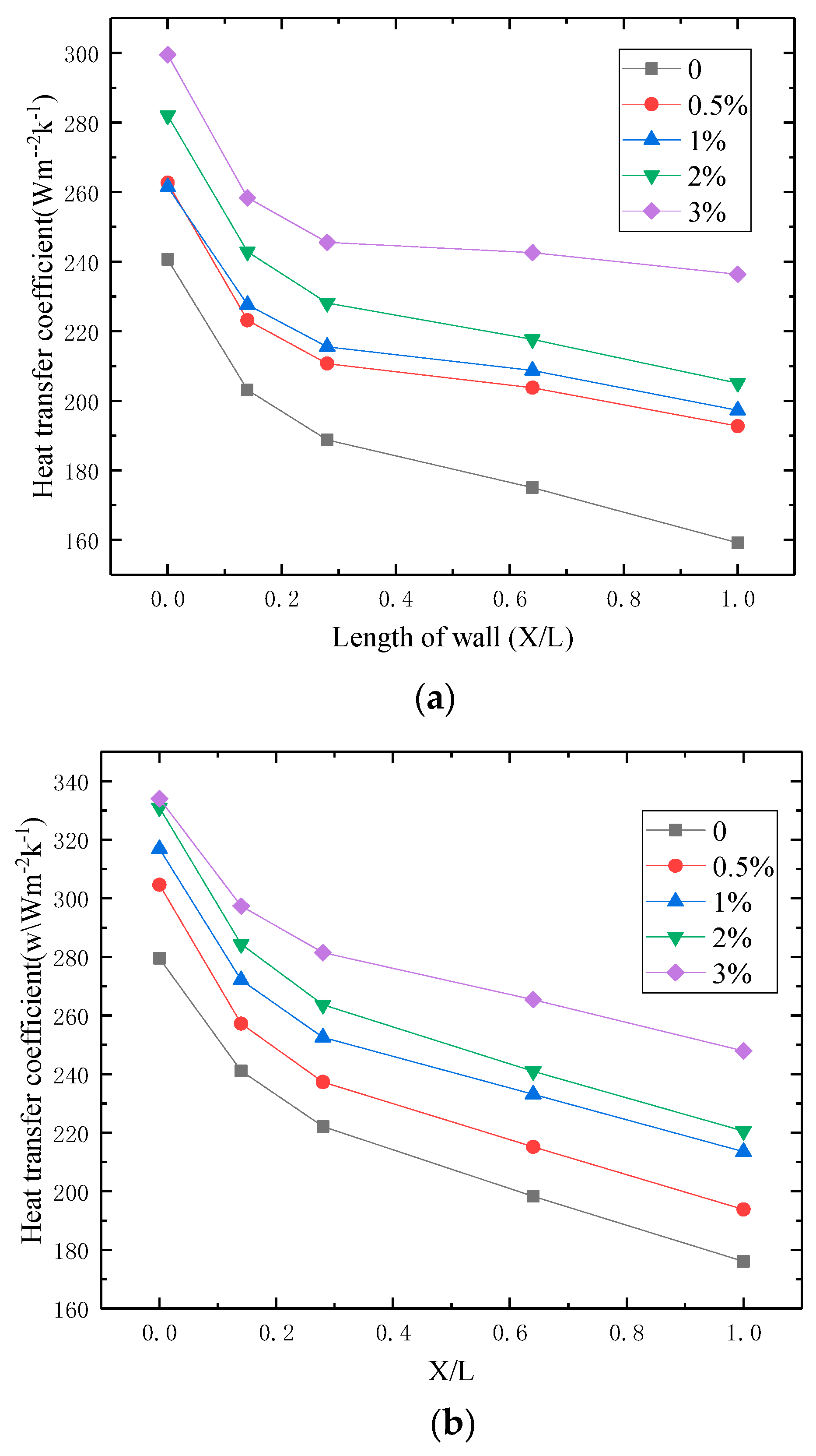
3.4. Heat Transfer Characteristics

Figure 10a,b shows the variation of wall temperature along the length of the round tube, respectively, when the nanofluid flow rates were 0.35 and 0.50 m/s. Because the fluid inlet temperature fluctuates slightly, the measured wall temperature was used to subtract the fluid inlet temperature as the excess wall temperature after normalization treatment. It can be seen in the figure that the excess wall temperature of lubricant with mass fractions of 0.5%, 1%, 2%, and 3% increased with the increase in tube length under the same flow rate, and when the velocity and position were constant, excess wall temperature decreased with the increase in graphene nanofluid concentration. With the same heating power, the fluid flow removes the same heat, and the lower the wall temperature, the stronger the heat transfer capacity. The heat transfer capacity of graphene lubricant nanofluids increased with the increase in concentration. Graphene has a high thermal conductivity, which can reach 5300 Wm−1k−1 theoretically, and the addition of graphene nanoparticles increases the thermal conductivity of graphene lubricant nanofluids. In addition, micro-turbulent flow may be developed around the dispersed particles to increase the intensity of the mixing of the fluid in the pipe, thus strengthening the heat transfer in the fluid.
Figure 11a,b, shows the nanofluid flow rates were 0.35 and 0.50 m/s, respectively, under the variation of convective heat transfer coefficient along the tube length. It can be seen in the figure that the convective heat transfer coefficient decreased gradually along the tube length direction because the whole tube was in the inlet section. The inlet effect reduced the convective heat transfer coefficient with the increase in tube length. At the same flow rate, the local convective heat transfer coefficient at the same position increased with the increase in nanofluid concentration in the graphene lubricant. When the flow rate was 0.35 m/s, the maximum was 48.50%. In particular, when Re was small, the fluid flow state was laminar flow, and the effect of the laminar bottom layer on heat transfer was obvious. After graphene nanoparticles were added into the base solution, the Brownian motion of particles increased, thermal conductivity improved and heat transfer obviously increased.
To better describe the variation of convective heat transfer, the relationship between the average convective heat transfer coefficient of graphene lubricant with different concentrations and flow rate is shown in Figure 12. It can be seen that the average convective heat transfer coefficient increased with the increase in flow rate and the gradual slowing of the growth rate. When the flow rate was equal, the average convective heat transfer coefficient increased with the increase in graphene mass concentration, which is consistent with the heat transfer characteristics of conventional fluids. However, when the mass concentration of graphene increased, the convective heat transfer coefficient increased due to Brownian motion and the collision of graphene particles.
To more clearly explain the relationship between flow and heat transfer, Figure 13 shows the relationship between the average Nusselt number (Nu) and Reynolds number (Re). When the concentration was equal, the convective heat transfer Nu of graphene lubricant increased with the increase in Re. When Re was equal, the convective heat transfer Nu increased with the increase in graphene particle concentration. It can be seen from the experimental results that when graphene particles were added into the lubricant, the maximum Nu increased by 40%. Moreover, with the increase in Re, graphene significantly improved the heat transfer characteristics of the lubricant. The analysis indicates that, when Re increased, the Brownian motion of graphene nanofluid was intense, effectively enhancing the heat transfer.

3.5. Discussion

In experimental research, numerous scholars have discussed the convective heat transfer characteristics of different nanofluids under various conditions. Yang et al.13] carried out an experimental study on the convective heat transfer coefficient of graphite water nanofluid in the laminar flow region, and measured the change in the convective heat transfer coefficient of different base solutions at different Reynolds numbers, temperatures, and volume concentrations. The experimental results show that with the increase in Reynolds number, the convective heat transfer coefficient of nanofluids also increases. With the increase in temperature, the magnitude of convective heat transfer coefficient increases gradually. Wen and Ding [12] studied the convective heat transfer coefficient of AL2O3-H2O nanofluid at the entrance of the laminar flow region. Results show that the convective heat transfer coefficient of AL2O3-H2O nanofluid increases with the increase in Reynolds number and volume concentration. The thermal development stage of A1203 monohydrate nanofluid is longer than that of pure water, which may be due to the Brownian motion of nanoparticles. The thermal boundary layer is weakened and the thermal conductivity and viscosity distribution are uneven. Amrolahi et al. [23] studied the convective heat transfer coefficient of multi-walled carbon nanotube water nanofluid under different flow states in a circular tube. The results show that when the mass fraction of multi-walled carbon nanotubes is 0.25%, the convective heat transfer coefficient of the nanofluid increases by 33–40%.
In this paper, a flow heat transfer experiment platform was built to study the flow and heat transfer characteristics of graphene lubricating oil in a horizontal circular tube. Findings were consistent with conclusions found in the literature, that is, the heat transfer characteristics of lubricant were improved. In future research, the convection heat transfer of lubricating oil in various enhanced heat exchange tubes will be studied.

4. Conclusions

In this paper, graphene nanoparticles were added to common lubricant and the physical properties were tested. Furthermore, an experimental study was conducted for flow and heat transfer characteristics. Results show that:
(1)
The graphene lubricant prepared using the two-step approach has good stability, according to examination via an electron microscope and centrifuge, with good dispersibility and no agglomeration.
(2)
The thermal conductivity and viscosity of the graphene lubricant increase with the increase in graphene concentration, and the thermal conductivity of the same concentration of graphene decreases with the increase in temperature.
(3)
The specific heat capacity of the graphene lubricant increases with the increase in temperature. At the same temperature, the specific heat capacity of nano-graphene lubricant is larger than that of base lubricant, and increases with the increase in graphene concentration.
(4)
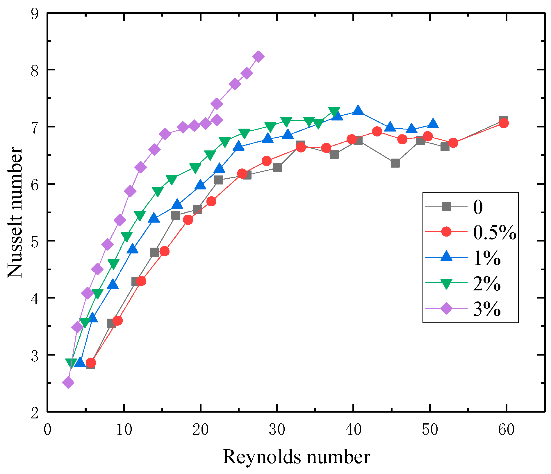
When the concentration is equal, the convective heat transfer Nu of graphene lubricant increases with the increase in Re. When Re is equal, the convective heat transfer Nu increases with the increase in the concentration of graphene particles, and the maximum Nu increases by 40%.

Author Contributions

Conceptualization, Z.C., M.T. and G.Z.; methodology, Z.C.; formal analysis, Z.C. and M.T.; investigation, Z.C. and M.T.; resources, M.T. and G.Z.; data curation, Z.C.; writing-original draft preparation, Z.C.; writing-review and editing, Z.C.; supervision, M.T. and G.Z.; funding acquisition, M.T. and G.Z. All authors have read and agreed to the published version of the manuscript.

Funding

The financial support from the National Natural Science Foundation of China (No. 51676114) is acknowledged.

Conflicts of Interest

The authors declare no conflict of interest.

References

  1. Uysal, S.C.; Liese, E.; Nix, A.C.; Black, J. A Thermodynamic Model to Quantify the Impact of Cooling Improvements on Gas Turbine Efficiency. J. Turbomach. 2018, 140. [Google Scholar] [CrossRef] [Green Version]
  2. Kapsiz, M.; Durat, M.; Ficici, F. Friction and wear studies between cylinder liner and piston ring pair using Taguchi design method. Adv. Eng. Softw. 2011, 42, 595–603. [Google Scholar] [CrossRef]
  3. Tung, S.C.; McMillan, M.L. Automotive tribology overview of current advances and challenges for the future. Tribol. Int. 2004, 37, 517–536. [Google Scholar] [CrossRef]
  4. Vianna, T.; Sworski, A.; Caudill, T.; Forbus, R. Student poster abstract: Investigations of lubrication circuit heat transfer rates using nanofluid and polypropylene glycol. Tribol. Lubr. Technol. 2010, 66, 16–17. [Google Scholar]
  5. Choi, S.U.S.; Eastman, J. Enhancing Thermal Conductivity of Fluids with Nanoparticles. In Proceedings of the 1995 International Mechanical Engineering Congress and Exhibition, San Francisco, CA, USA, 12–17 November 1995; Volume 66. [Google Scholar]
  6. Ahmadi, M.H.; Mirlohi, A.; Alhuyi Nazari, M.; Ghasempour, R. A review of thermal conductivity of various nanofluids. J. Mol. Liq. 2018, 265, 181–188. [Google Scholar] [CrossRef]
  7. Pelević, N.; van der Meer, T.H. Numerical investigation of the effective thermal conductivity of nano-fluids using the lattice Boltzmann model. Int. J. Therm. Sci. 2012, 62, 154–159. [Google Scholar] [CrossRef]
  8. Tawfik, M.M. Experimental studies of nanofluid thermal conductivity enhancement and applications: A review. Renew. Sustain. Energy Rev. 2017, 75, 1239–1253. [Google Scholar] [CrossRef] [Green Version]
  9. Fotukian, S.M.; Nasr Esfahany, M. Experimental investigation of turbulent convective heat transfer of dilute γ-Al2O3/water nanofluid inside a circular tube. Int. J. Heat Fluid Flow 2010, 31, 606–612. [Google Scholar] [CrossRef]
  10. Abbasian Arani, A.A.; Amani, J. Experimental investigation of diameter effect on heat transfer performance and pressure drop of TiO2–water nanofluid. Exp. Therm. Fluid Sci. 2013, 44, 520–533. [Google Scholar] [CrossRef]
  11. Zeinali Heris, S.; Etemad, S.G.; Nasr Esfahany, M. Experimental investigation of oxide nanofluids laminar flow convective heat transfer. Int. Commun. Heat Mass Transf. 2006, 33, 529–535. [Google Scholar] [CrossRef]
  12. Wen, D.; Ding, Y. Experimental investigation into convective heat transfer of nanofluids at the entrance region under laminar flow conditions. Int. J. Heat Mass Transf. 2004, 47, 5181–5188. [Google Scholar] [CrossRef]
  13. Yang, Y.; Zhang, Z.G.; Grulke, E.A.; Anderson, W.B.; Wu, G. Heat transfer properties of nanoparticle-in-fluid dispersions (nanofluids) in laminar flow. Int. J. Heat Mass Transf. 2005, 48, 1107–1116. [Google Scholar] [CrossRef]
  14. Geim, A.K.; Novoselov, K.S. The rise of graphene. Nat. Mater. 2007, 6, 183–191. [Google Scholar] [CrossRef]
  15. Singh, V.; Joung, D.; Zhai, L.; Das, S.; Khondaker, S.I.; Seal, S. Graphene based materials: Past, present and future. Prog. Mater. Sci. 2011, 56, 1178–1271. [Google Scholar] [CrossRef]
  16. Novoselov, K.S.; Geim, A.K.; Morozov, S.V.; Jiang, D.; Katsnelson, M.I.; Grigorieva, I.V.; Dubonos, S.V.; Firsov, A.A. Two-dimensional gas of massless Dirac fermions in graphene. Nature 2005, 438, 197–200. [Google Scholar] [CrossRef]
  17. Balandin, A.A.; Ghosh, S.; Bao, W.; Calizo, I.; Teweldebrhan, D.; Miao, F.; Lau, C.N. Superior thermal conductivity of single-layer graphene. Nano Lett. 2008, 8, 902–907. [Google Scholar] [CrossRef]
  18. Lee, C.; Wei, X.; Kysar, J.W.; Hone, J. Measurement of the Elastic Properties and Intrinsic Strength of Monolayer Graphene. Science 2008, 321, 385–388. [Google Scholar] [CrossRef]
  19. Baby, T.; Sundara, R. Enhanced convective heat transfer using graphene dispersed nanofluids. Nanoscale Res. Lett. 2011, 6, 289. [Google Scholar] [CrossRef] [Green Version]
  20. Ma, W.; Yang, F.; Shi, J.; Wang, F.; Zhang, Z.; Wang, S. Silicone based nanofluids containing functionalized graphene nanosheets. Colloids Surf. A Physicochem. Eng. Asp. 2013, 431, 120–126. [Google Scholar] [CrossRef]
  21. Hajjar, Z.; Rashidi, A.M.; Ghozatloo, A. Enhanced thermal conductivities of graphene oxide nanofluids. Int. Commun. Heat Mass Transf. 2014, 57, 128–131. [Google Scholar] [CrossRef]
  22. Rasheed, A.K.; Khalid, M.; Rashmi, W.; Gupta, T.C.S.M.; Chan, A. Graphene based nanofluids and nanolubricants—Review of recent developments. Renew. Sustain. Energy Rev. 2016, 63, 346–362. [Google Scholar] [CrossRef]
  23. Amrollahi, A.; Rashidi, A.M.; Lotfi, R. Convection heat transfer of functionalized MWNT in aqueous fluids in laminar and turbulent flow at the entrance region. Int. Commun. Heat Mass Transf. 2010, 37, 717–723. [Google Scholar] [CrossRef]
Figure 1. SEM image of graphene.
Processes 08 01675 g001
Figure 2. The images of prepared nanofluid samples under multifunctional stereomicroscope.
Processes 08 01675 g002
Figure 3. Separation images of graphene lubricant oil at different centrifugal speeds.
Processes 08 01675 g003
Figure 4. Thermal conductivity of prepared nanofluid samples with different mass fraction.
Processes 08 01675 g004
Figure 5. Thermal conductivity of prepared nanofluid samples at different temperatures.
Processes 08 01675 g005
Figure 6. Viscosity of prepared nanofluid samples at different temperatures.
Processes 08 01675 g006
Figure 7. Specific heat capacity of prepared nanofluid samples at different temperature.
Processes 08 01675 g007
Figure 8. Schematic diagram of the experimental setup.
Processes 08 01675 g008
Figure 9. Pressure drop of prepared nanofluid samples at different Reynolds numbers.
Processes 08 01675 g009
Figure 10. Wall temperature for different samples along the tube length at different flow rates: (a) flow rate u = 0.35 m/s; (b) flow rate u = 0.50 m/s.
Processes 08 01675 g010
Figure 11. Local heat transfer coefficient for different samples along the tube length at different flow rates: (a) flow rate u = 0.35 m/s; (b) flow rate u = 0.50 m/s.
Processes 08 01675 g011
Figure 12. Heat transfer coefficient of prepared nanofluid samples at different velocities.
Processes 08 01675 g012
Figure 13. Nusselt number of prepared nanofluid samples at different Reynolds numbers.
Processes 08 01675 g013
Table 1. The physical parameters of graphene.
ModelExteriorSpecific Area (≥m2/g)Particle Size (D50, μm)The Mass Fraction of Carbon (%)Thickness (nm)
N002-PDRBlack powder500–800<10.095<10
Table 2. The coefficients and viscosity index.
Weight Friction (%)ABCViscosity Index
06.15 × 101015.6226.83244
0.54.52 × 101015.9125.22244
11.89 × 101114.8833.49253
28.45 × 101015.5941.28284
32.12 × 101115.2163.03291
Publisher’s Note: MDPI stays neutral with regard to jurisdictional claims in published maps and institutional affiliations.

