Valorization of OFMSW Digestate-Derived Syngas toward Methanol, Hydrogen, or Electricity: Process Simulation and Carbon Footprint Calculation


Abstract
:
1. Introduction
2. Materials and Methods
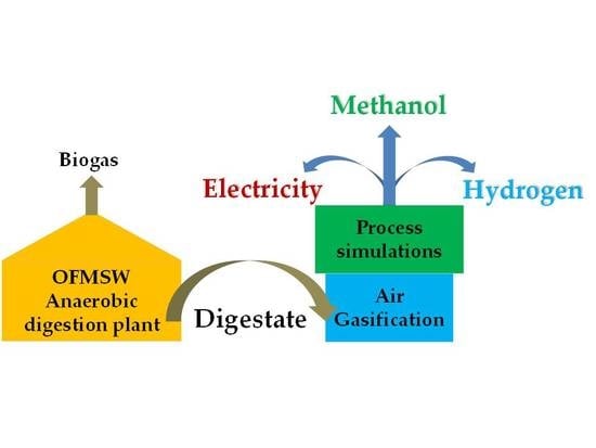
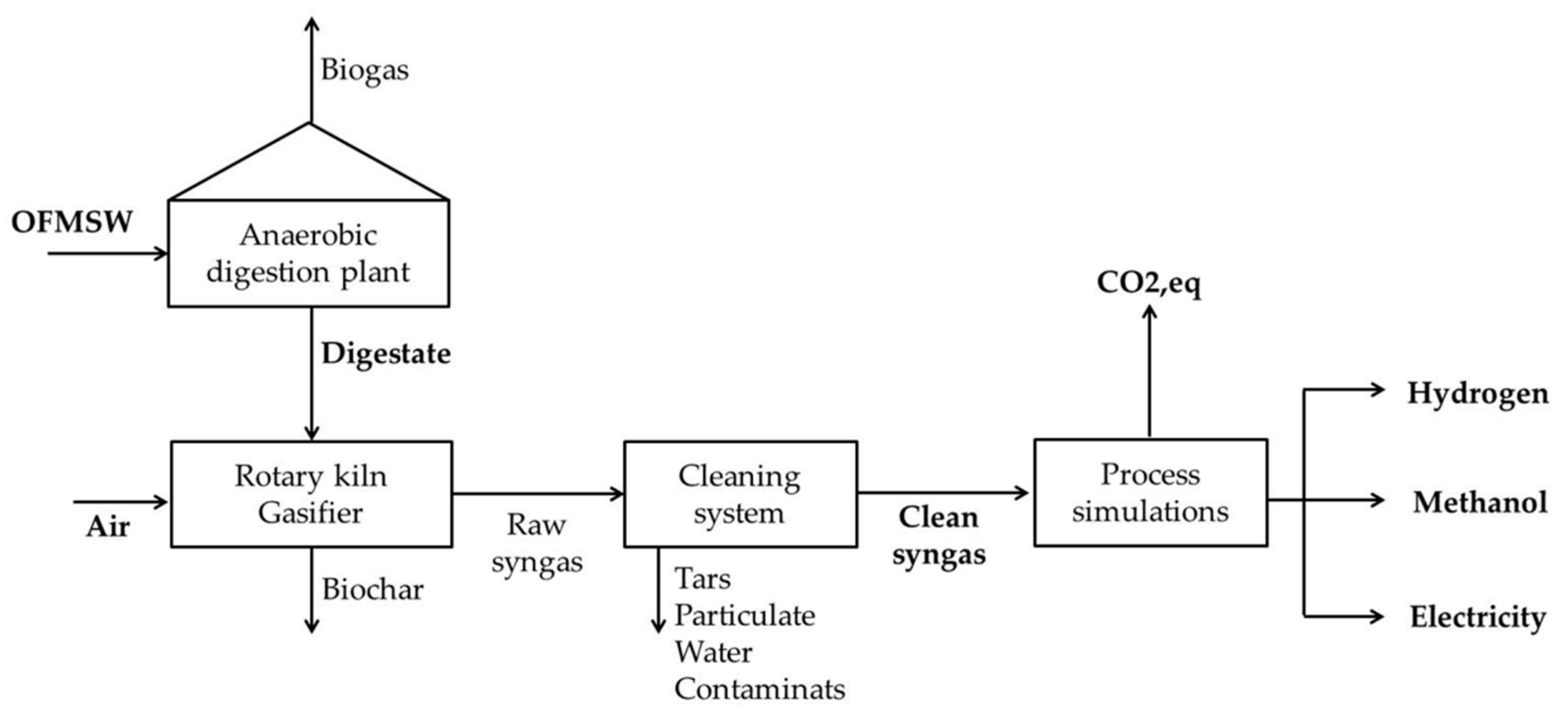
2.1. Process Simulation
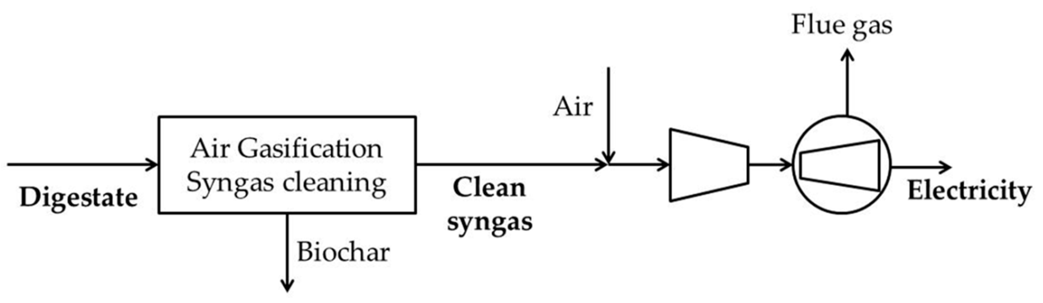
2.1.1. Case-EL
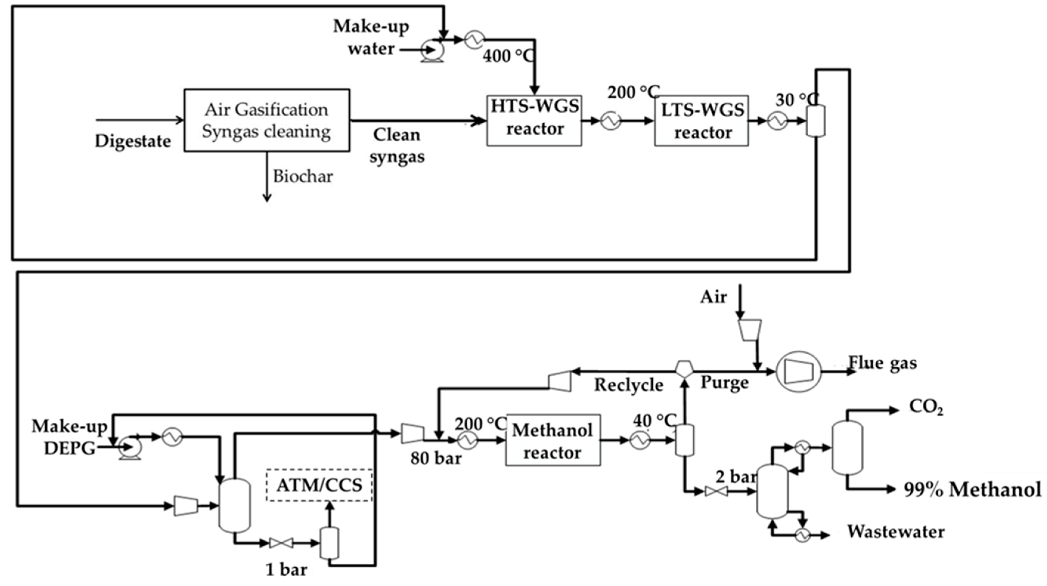
2.1.2. Case-MeOH
Water Gas Shift (WGS) Section
CO2 Capture Section
Methanol Production and Purification Section
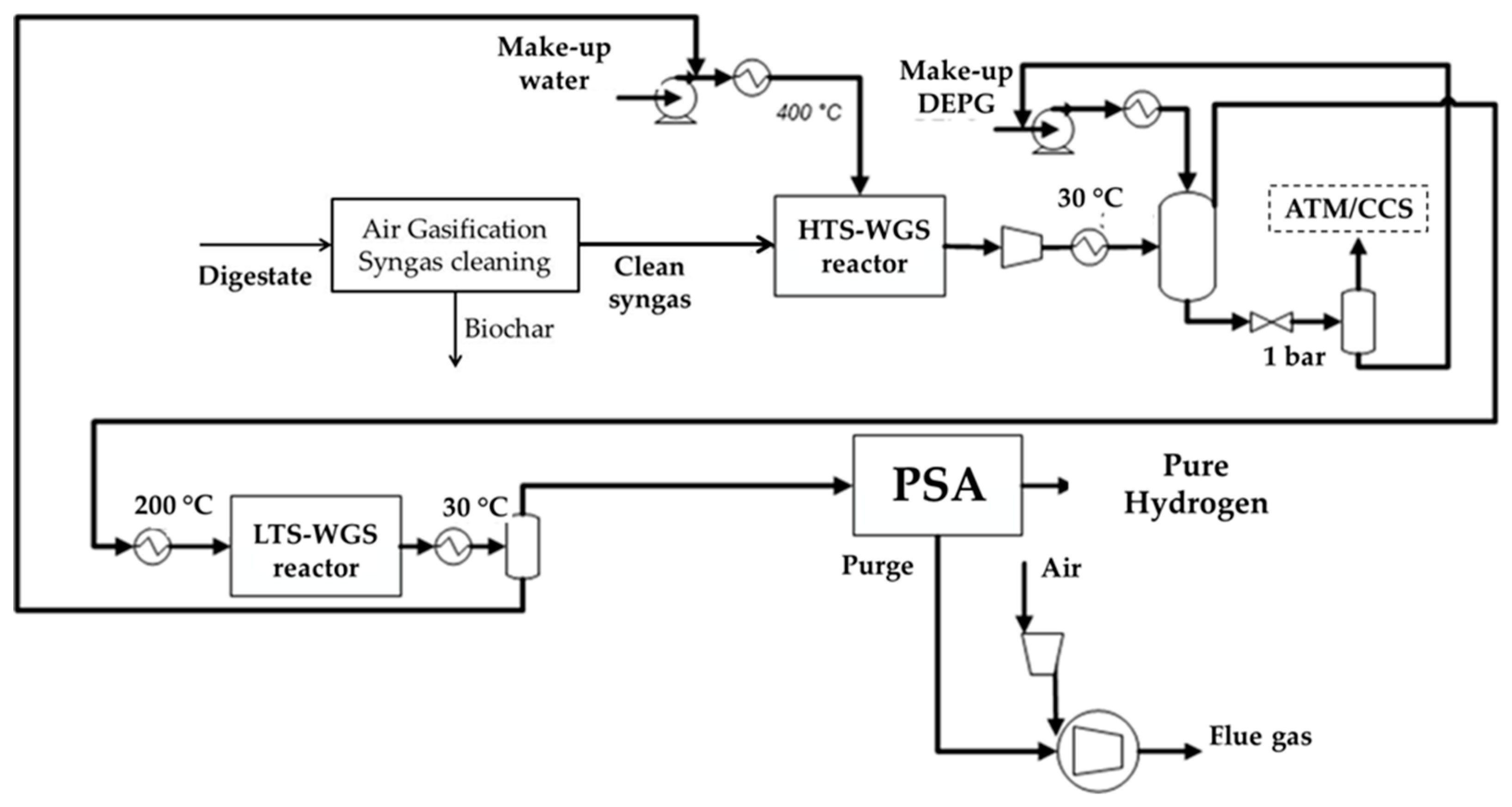
2.1.3. Case-H2
2.2. Environmental Impact Analysis
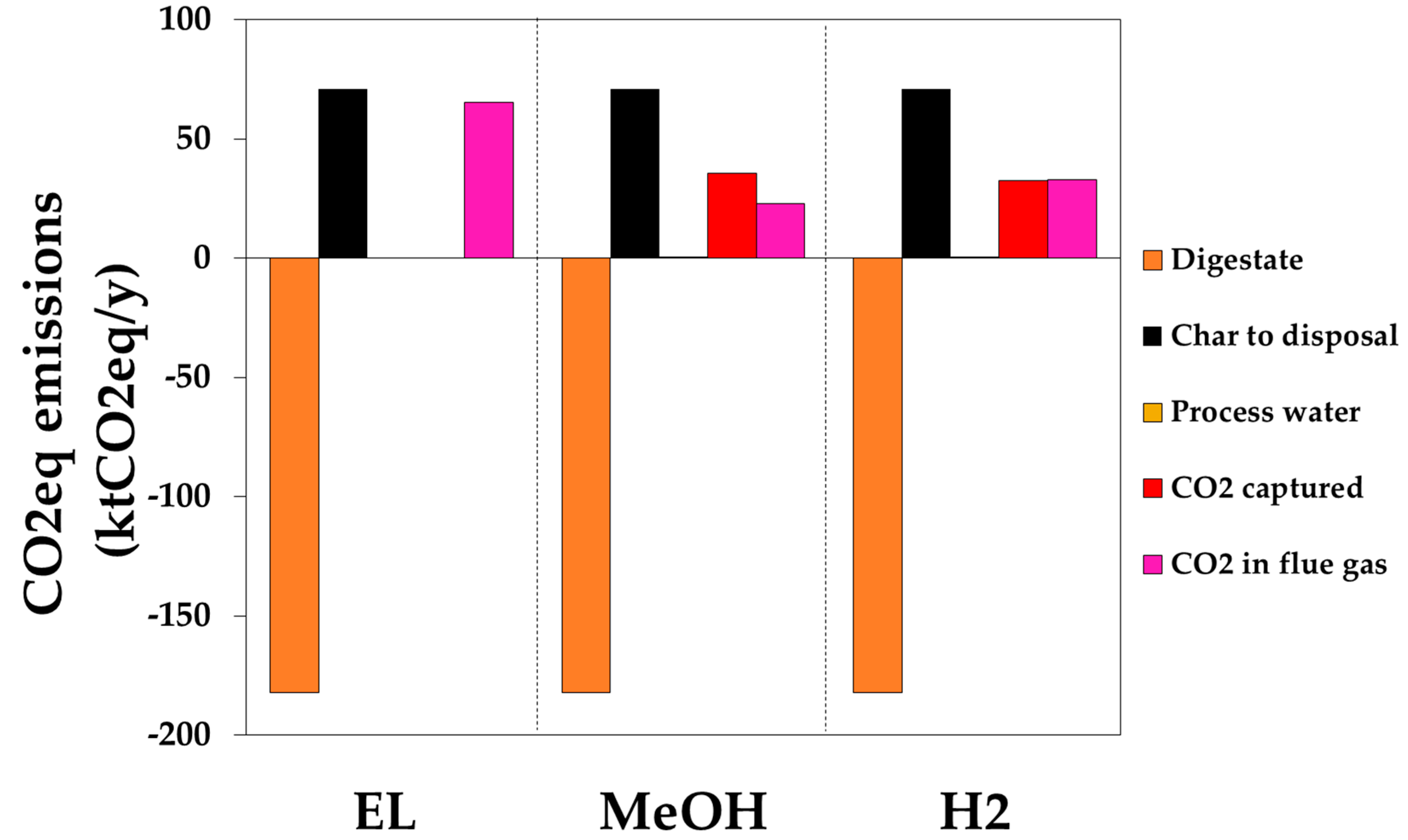
- -
- Residual biochar disposal after the gasification process in a landfill (BC);
- -
- Process water utilization for the WGS reaction, also considering detoxification and demineralization processes (PW).
- -
- CO2 in the flue gases of the combustion of purge gas or of syngas for the case EL (FG);
- -
- CO2 derived by carbon capture section for the cases without CO2 compression and storage (CC).
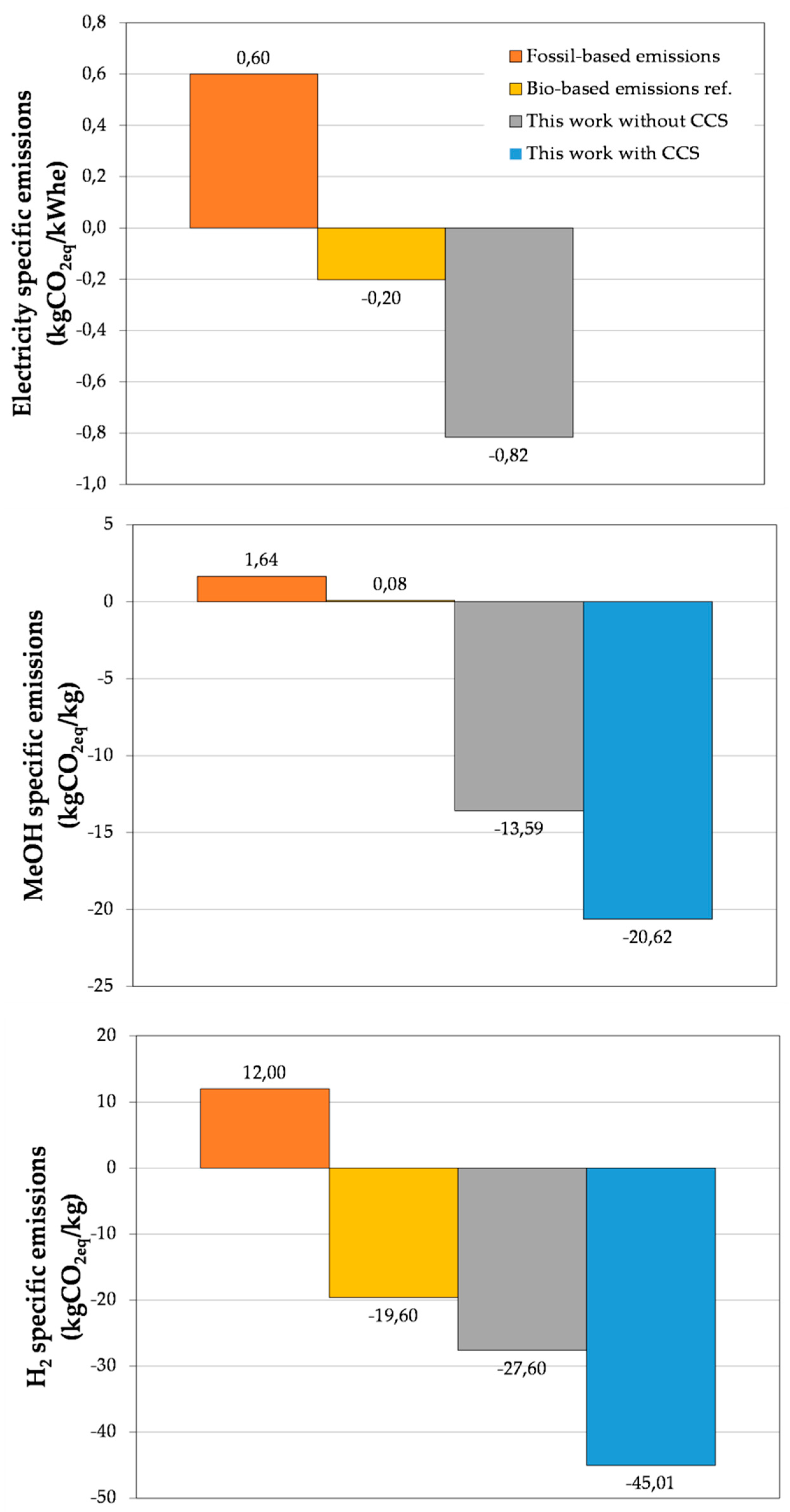
3. Results and Discussion
CO2-Equivalent Emission Calculation
4. Conclusions
Author Contributions
Funding
Conflicts of Interest
References
- Demirbas, A. Waste management, waste resource facilities and waste conversion processes. Energy Conv. Manag. 2011, 52, 1280–1287. [Google Scholar] [CrossRef]
- Ali, R.A.; Ibrahim, N.N.L.N.; Lam, H.L. Conversion technologies: Evaluation of economic performance and environmental impact analysis for municipal solid waste in Malesya. Processes 2019, 7, 752. [Google Scholar] [CrossRef] [Green Version]
- World Bank. What a Waste: A Global Review of Solid Waste Management; Urban Develop Series Knowledge Paper No. 15; World Bank: Washington, DC, USA, 2012; p. 116. [Google Scholar] [CrossRef]
- Arent, D.J.; Wise, A.; Gelman, R. The status and prospects of renewable energy for combating global warming. Energy Econ. 2011, 33, 584–593. [Google Scholar] [CrossRef]
- Migliori, M.; Catizzone, E.; Giordano, G.; Le Pera, A.; Sellaro, M.; Lista, A.; Zanardi, G.; Zoia, L. Pilot plant assessment in anaerobic digestion of organic fraction of municipal waste solids. Processes 2019, 7, 54. [Google Scholar] [CrossRef] [Green Version]
- Chow, W.L.; Chong, S.; Lim, J.W.; Chan, Y.J.; Chong, M.F.; Tiong, T.J.; Chin, J.K.; Pan, G.-T. Anerobic co-digestion of wastewater sludge: A review of potential co-substrates and operating factors for improved methane yield. Processes 2020, 8, 39. [Google Scholar] [CrossRef] [Green Version]
- Ramachandran, A.; Rustum, R.; Adeloye, A.J. Review of anaerobic digestion modeling and optimization using nature-inspired techniques. Processes 2019, 7, 953. [Google Scholar] [CrossRef] [Green Version]
- Dry, M.E. High quality diesel via the Fischer-Tropsch process–a review. J. Chem. Technol. Biotechnol. 2002, 77, 43–50. [Google Scholar] [CrossRef]
- Catizzone, E.; Bonura, G.; Migliori, M.; Frusteri, F.; Giordano, G. CO2 recycling to dimethyl ether: State-of-the-art and perspectives. Molecules 2018, 23, 31. [Google Scholar] [CrossRef] [Green Version]
- Bonura, G.; Cannilla, C.; Frusteri, L.; Catizzone, E.; Todaro, S.; Migliori, M.; Giordano, G.; Frusteri, F. Interaction effects between CuO-ZnO-ZrO2 methanol phase and zeolite surface affecting stability of hybrid systems during one-step CO2 hydrogenation to DME. Catal.Today 2000, 345, 175–182. [Google Scholar] [CrossRef]
- Esmaeili, J.; Rahimpour, F. Regeneration of spent nickel catalyst from hydrogenation process of edible oils: Heat treatment with hydrogen injection. Int. J. Hydrogen Energy 2017, 42, 24197–24204. [Google Scholar] [CrossRef]
- Lanzafame, P.; Centi, G.; Perathoner, S. Catalysis for biomass and CO2 use through solar energy: Opening new scenarios for a sustainable and low-carbon chemical production. Chem. Soc. Rev. 2014, 43, 7562–7580. [Google Scholar] [CrossRef] [PubMed]
- Smolińaki, A.; Howaniec, N. Co-gasification of coal/sewage sludge blends to hydrogen-rich gas with the application of simulated high temperature reactor excess heat. Int. J. Hydrogen Energy 2016, 41, 8154–8158. [Google Scholar] [CrossRef]
- Bagnato, G.; Sanna, A. Process and techno-economic analysis for fuel and chemical production by hydrodeoxygenation of bio-oil. Catalysts 2019, 9, 1021. [Google Scholar] [CrossRef] [Green Version]
- Chiodini, A.; Bua, L.; Carnelli, L.; Zwart, R.; Vreugdenhil, B.; Vocciante, M. Enhancements in Biomass-to-Liquid processes: Gasification aiming at high hydrogen/carbon monoxide ratios for direct Fischer-Tropsch synthesis applications. Biomass Bioenergy 2017, 106, 104–114. [Google Scholar] [CrossRef]
- Giuliano, A.; Barletta, D.; De Bari, I.; Poletto, M. Techno-economic assessment of a lignocellulosic biorefinery co-producing ethanol and xylitol or furfural. Comput. Aided Chem. Eng. 2018, 43, 585–590. [Google Scholar]
- Fasolini, A.; Cucciniello, R.; Paone, E.; Mauriello, F.; Tabanelli, T. A Short Overview on the Hydrogen Production Via Aqueous Phase Reforming (APR) of Cellulose, C6-C5 Sugars and Polyols. Catalysts 2019, 9, 917. [Google Scholar] [CrossRef] [Green Version]
- Paone, E.; Tabanelli, T.; Mauriello, F. The rise of lignin biorefinery. Current Opin. Green Sus. Chem. 2020, 24, 1–6. [Google Scholar]
- Lin, R.-H.; Xi, X.-N.; Wang, P.-N.; Wu, B.-D.; Tian, S.-M. Review on hydrogen fuel cell condition monitoring and prediction methods. Int. J. Hydrogen Energy 2019, 44, 5488–5498. [Google Scholar] [CrossRef]
- Olah, G.A. Beyond oil and gas: The methanol economy. Angew. Chem. Int. Ed. 2005, 44, 2636–2639. [Google Scholar] [CrossRef]
- Qian, Q.; Zhang, J.; Cui, M.; Han, B. Synthesis of acetic acid via methanol hydrocarboxylation with CO2 and H2. Nat. Commun. 2016, 7, 11481. [Google Scholar] [CrossRef] [Green Version]
- Keil, F.J. Methanol-to-hydrocarbons: Process technology. Microp. Mesop. Mater. 1999, 29, 49–66. [Google Scholar] [CrossRef]
- Catizzone, E.; Cirelli, Z.; Aloise, A.; Lanzafame, P.; Migliori, M.; Giordano, G. Methanol conversion over ZSM-12, ZSM-22 and EU-1 zeolites: From DME to hydrocarbons production. Catal. Today 2018, 304, 39–50. [Google Scholar] [CrossRef]
- Catizzone, E.; Van Daele, S.; Bianco, M.; Di Michele, A.; Aloise, A.; Migliori, M.; Valtchev, V.; Giordano, G. Catalytic application of ferrierite nanocrystals in vapour-phase dehydration of methanol to dimethyl ether. Appl. Catal. B Environ. 2019, 243, 273–282. [Google Scholar] [CrossRef]
- Migliori, M.; Catizzone, E.; Aloise, A.; Bonura, G.; Gómez-Hortigüela, L.; Frusteri, L.; Cannilla, C.; Frusteri, F.; Giordano, G. New insights about coke deposition in methanol-to-DME reaction over MOR-, MFI-, and FER-type zeolites. J. Ind. Eng. Chem. 2018, 68, 196–208. [Google Scholar] [CrossRef]
- Catizzone, E.; Aloise, A.; Migliori, M.; Giordano, G. The effect of FER zeolite acid sites in methanol-to-dimethyl ether catalytic dehydration. J. Energy Chem. 2017, 26, 406–415. [Google Scholar] [CrossRef] [Green Version]
- Peng, W.; Lü, F.; Hao, L.; Zhang, H.; Shao, L.; He, P. Digestate management for high-solid anaerobic digestion of organic wastes: A review. Bioresour. Technol. 2020, 297, 122485. [Google Scholar] [CrossRef]
- Chiumenti, A.; Da Borso, F.; Chiumenti, R.; Segantin, P. Treatment of digestate from a co-digestion biogas plant by means of vacuum evaporation: Tests for process optimization and environmental sustainability. Waste Manag. 2013, 33, 1339–1344. [Google Scholar] [CrossRef]
- Rehl, T.; Müller, J. Life cycle assessment of biogas digestate processing technologies. Res. Convers. Recycl. 2011, 56, 92–104. [Google Scholar] [CrossRef]
- Calabrò, P.S.; Fazzino, F.; Folino, A.; Paone, E.; Komila, D. Semi-continuous anaerobic digestion of orange peel waste: Effect of activated carbon addition and alkaline pretreatment on the process. Sustainability 2019, 11, 3386. [Google Scholar] [CrossRef] [Green Version]
- Banks, C.J.; Chesshire, M.; Heaven, S.; Arnold, R. Anaerobic digestion of source-segregated domestic food waste: Performance assessment by mass and energy balance. Bioresour. Technol. 2011, 102, 612–620. [Google Scholar] [CrossRef] [Green Version]
- Monlau, F.; Francavilla, M.; Sambusiti, C.; Antoniou, N.; Solhy, A.; Libutti, A.; Zabaniotou, A.; Barakat, A.; Monteleone, M. Toward a functional integration of anaerobic digestion and pyrolysis for a sustainable resource management. Comparison between solid-digestate and its derived pyrochar as soil amendment. Appl. Energy 2016, 169, 652–662. [Google Scholar] [CrossRef]
- Pedrazzi, S.; Allesina, G.; Bellò, T.; Rinaldini, C.A.; Tartarini, P. Digestate as bio-fuel in domestic furnaces. Fuel Process. Technol. 2015, 130, 172–178. [Google Scholar] [CrossRef]
- Opatokun, S.A.; Kan, T.; Al Shoaibi, A.A.; Srinivasakannan, C.; Strezov, V. Characterization of food waste and its digestate as feedstock for thermochemical processing. Energy Fuel 2016, 30, 1589–1597. [Google Scholar] [CrossRef]
- Opatokun, S.A.; Strezov, V.; Kan, T. Product based evaluation of pyrolysis of food waste and its digestate. Energy 2015, 92, 349–354. [Google Scholar] [CrossRef]
- Sharifzadeh, M.; Sadeqzadeh, M.; Guo, M.; Borhani, T.; Konda, N.V.S.N.M.; Cortada Garcia, M.; Wang, L.; Hallet, J.; Shah, N. The multi-scale challenges of biomass fast pyrolysis and bio-oil upgrading: Review of the state of art and future research directions. Progress. Energy Comb. Sci. 2019, 71, 1–80. [Google Scholar] [CrossRef]
- Fabbri, D.; Torri, C. Linking pyrolysis and anaerobic digestion (Py-AD) for the conversion of lignocellulosic biomass. Curr. Opin. Biotechnol. 2016, 38, 167–173. [Google Scholar] [CrossRef]
- Barisano, D.; Freda, C.; Nanna, F.; Fanelli, E.; Villone, A. Biomass gasification and in-bed contaminants removal: Performance of iron enriched Olivine and bauxite in a process of steam/O2 gasification. Bioresour. Technol. 2012, 118, 187–194. [Google Scholar] [CrossRef]
- Freda, C.; Cornacchia, G.; Romanelli, A.; Valerio, V.; Grieco, M. Sewage sludge gasification in a bench scale rotary kiln. Fuel 2018, 212, 88–94. [Google Scholar] [CrossRef]
- Pecchi, M.; Baratieri, M. Coupling anaerobic digestion with gasification, pyrolysis or hydrothermal carbonization: A review. Renew. Sustain. Energy Rev. 2019, 105, 462–475. [Google Scholar] [CrossRef]
- Macrì, D.; Catizzone, E.; Molino, A.; Migliori, M. Supercritical waster gasification of biomass and agro-food residues: Energy assessment from modelling approach. Renew. Energy 2020, 150, 624–636. [Google Scholar] [CrossRef]
- Chen, G.; Guo, X.; Cheng, Z.; Yan, B.; Dan, Z.; Ma, W. Air gasification of biogas-derived digestate in a downdraft fixed bed gasifier. Waste Manag. 2017, 69, 162–169. [Google Scholar] [CrossRef] [PubMed]
- Gnanendra, P.M.; Ramesha, D.K.; Dasappa, S. Preliminary investigation on the use of biogas sludge for gasification. Intern. J. Sustain. Energy 2012, 31, 251–267. [Google Scholar] [CrossRef]
- Freda, C.; Nanna, F.; Villone, A.; Barisano, D.; Brandani, S.; Cornacchia, G. Air gasification of digestate and its co-gasification with residual biomass in a pilot scale rotary kiln. Int. J. Energy Environ. Eng. 2019, 10, 335–346. [Google Scholar] [CrossRef] [Green Version]
- Boateng, A. Rotary Kilns Transport Phenomena and Transport Processes; Butterworth-Heinemann by Elsevier: Amsterdam, The Netherlands, 2008. [Google Scholar]
- Notarnicola, M.; Cornacchia, G.; De Gisi, S.; Di Canio, F.; Freda, C.; Garzone, P.; Martino, M.; Valerio, V.; Villone, A. Pyrolysis of automotive shredder residue in a bench scale rotary kiln. Waste Manag. 2017, 65, 92–103. [Google Scholar] [CrossRef]
- Shi, H.; Si, W.; Li, X. The concept, design and performance of a novel rotary kiln type air-staged biomass gasifier. Energies 2016, 9, 67. [Google Scholar] [CrossRef] [Green Version]
- Benanti, E.; Freda, C.; Lorefice, V.; Braccio, G.; Sharma, V.K. Simulation of olive pits pyrolysis in a rotary kiln. Therm. Sci. 2011, 15, 145–158. [Google Scholar] [CrossRef]
- Fanelli, E.; Freda, C.; Canneto, G.; Barisano, D.; Nanna, F.; Braccio, G. Experimentation of a down-draft gasifier coupled with an Internal Combustion Engine (ICE) for theoretical model validation. In Proceedings of the 4th International Conference on Biomass for Energy, Kyiv, Ukraine, 22–24 September 2008. [Google Scholar]
- Monlau, F.; Sambusiti, C.; Aboulkas, A.; Barakat, A.; Carrère, H. New opportunities for agricultural digestate valorisation: Current situation and perspectives. Energy Environ. Sci. 2015, 8, 2600–2621. [Google Scholar] [CrossRef]
- Antoniu, N.; Monlau, F.; Sambusiti, C.; Ficara, E.; Barakat, A.; Zabaniotou, A. Contribution to Circular Economy options of mixed agricultural wastes management: Coupling anaerobic digestion with gasification for enhanced energy and material recovery. J. Clean. Prod. 2019, 209, 505–514. [Google Scholar] [CrossRef]
- Milani, M.; Montorsi, L.; Stefani, M. An integrated approach to energy recovery from biomass and waste: Anaerobic digestion-gasification-water treatment. Waste Manag. Res. 2014, 32, 614–625. [Google Scholar] [CrossRef]
- Giuliano, A.; Poletto, M.; Barletta, D. Process Design of a Multi-Product Lignocellulosic Biorefinery. Comput. Aided Chem. Eng. 2015, 37, 1313–1318. [Google Scholar]
- Borgogna, A.; Salladini, A.; Spadacini, L.; Pitrelli, A.; Annesini, M.C.; Iaquaniello, G. Methanol production from Refuse Derived Fuel: Influence of feedstock composition on process yield through gasification analysis. J. Clean. Prod. 2019, 235, 1080–1089. [Google Scholar] [CrossRef] [Green Version]
- Iaquaniello, G.; Centi, G.; Salladini, A.; Palo, E.; Spadacini, L. Waste-to-methanol: Process and economics assessment. Bioresour. Technol. 2017, 243, 611–619. [Google Scholar] [CrossRef] [PubMed]
- Bozzano, G.; Manenti, F. Efficient methanol synthesis: Perspectives, technologies and optimization strategies. Progr. Energy Comb. Sci. 2016, 56, 71–105. [Google Scholar] [CrossRef]
- Giuliano, A.; Poletto, M.; Barletta, D. Pure hydrogen co-production by membrane technology in an IGCC power plant with carbon capture. Int. J. Hydrogen Energy 2018, 43, 19279–19292. [Google Scholar] [CrossRef]
- Sofia, D.; Giuliano, A.; Poletto, M.; Barletta, D. Techno-economic analysis of power and hydrogen co-production by an IGCC plant with CO2 capture based on membrane technology. Comp. Aided Chem. Eng. 2015, 37, 1373–1378. [Google Scholar]
- Van Dijk, E.; Walspurger, S.; Cobden, P.; Van Den Brinck, R. Testing of hydrotalcite based sorbents for CO2 and H2S capture for use in sorption enhanced water gas shift. Energy Procedia 2011, 4, 1110–1117. [Google Scholar] [CrossRef] [Green Version]
- Ward, C.; Goldstein, H.; Maurer, R.; Thimsen, D.; Sheets, B.J.; Hobbs, R.; Isgrigg, F.; Steiger, R.; Madden, D.R.; Porcu, A.; et al. Making coal relevant for small scale applications: Modular gasification for syngas/engine CHP applications in challenging environments. Fuel 2020, 267, 117303. [Google Scholar] [CrossRef]
- Giuliano, A.; Catizzone, E.; Barisano, D.; Nanna, F.; Villone, A.; De Bari, I.; Cornacchia, G.; Braccio, G. Towards methanol economy: A techno-envoronmental assessment for a bio-methanol OFMSW/Biomass/Carbon Capture-based integrated plant. Int. J. Heat Technol. 2019, 37, 665–674. [Google Scholar] [CrossRef]
- Hilde, J.V.; Yiang, J. Catalysis in microstructured reactors: Short review on small-scale syngas production andfurther conversion into methanol, DME and Fisher-Tropsch products. Catal. Today 2017, 285, 135–146. [Google Scholar]
- Giuliano, A.; De Bari, I.; Motola, V.; Pierro, N.; Giocoli, A.; Barletta, D. Techno-environmental assessment of two biorefinery systems to valorise the residual lignocellulosic biomass of the Basilicata region. Math. Modell. Eng. Probl. 2019, 6, 317–323. [Google Scholar] [CrossRef]
- Rodrigues Gurgel da Silva, A.; Giuliano, A.; Errico, M.; Rong, B.-G.; Barletta, D. Economic value and environmental impact analysis of lignocellulosic ethanol production: Assessment of different pretreatment processes. Clean Technol. Environ. Policy 2019, 21, 637–654. [Google Scholar] [CrossRef]
- Perez, J.; De Andres, M.J.; Lumbreras, J.; Rodriguez, E. Evaluating carbon footprint of municipal solid waste treatment: Methodological proposal and application to a case study. J. Clean. Prod. 2018, 205, 419–431. [Google Scholar] [CrossRef]
- Li, J.; Ma, X.; Liu, H.; Zhang, X. Life cycle assessment and economic analysis of methanol production from coke oven gas compared with coal and natural gas routes. J. Clean. Prod. 2018, 185, 299–308. [Google Scholar] [CrossRef]
- Bareiß, K.; De, C.; Möckl, M.; Hamacher, T. Life cycle assessment of hydrogen from proton exchange membrane water electrolysis in future energy systems. Appl. Energy 2019, 237, 862–872. [Google Scholar] [CrossRef]
- Zhang, Y.; Xiao, J.; Shen, L. Simulation of Methanol Production from Biomass Gasification in Interconnected Fluidized Beds. Ind. Eng. Chem. Res. 2009, 48, 5351–5359. [Google Scholar] [CrossRef]
- Ptasinski, K.J.; Hamelinck, C.; Kerkhof, P.J.A.M. Exergy analysis of methanol from the sewage sludge process. Energy Convers. Manag. 2002, 43, 1445–1457. [Google Scholar] [CrossRef]
- Yang, S.; Li, B.; Zheng, J.; Kankala, R.K. Biomass-to-Methanol by dual-stage entrained flow gasification: Design and techno-economic analysis based on system modelling. J. Clean. Prod. 2018, 205, 364–374. [Google Scholar] [CrossRef]
- Toonssen, R.; Woudstra, N.; Verkooijen, A.H.M. Exergy analysis of hydrogen production plants based on biomass gasification. Int. J. Hydrogen Energy 2008, 33, 4074–4082. [Google Scholar] [CrossRef]
- Heyne, S.; Thunman, H.; Harvey, S. Exergy-based comparison of indirect and direct biomass gasification technologies within the framework of bio-SNG production. Biomass Convers. Biorefinery 2013, 3, 337–352. [Google Scholar] [CrossRef] [Green Version]
- Hamelinck, C.N.; Faaij, P.C. Future prospects for production of methanol and hydrogen from biomass. J. Power Sources 2002, 111, 1–22. [Google Scholar] [CrossRef]
- Lv, P.; Yuan, Z.; Ma, L.; Wu, C.; Chen, Y.; Zhu, J. Hydrogen-rich gas production from biomass air and oxygen/steam gasification in downdraft gasifier. Renew. Energy 2007, 32, 2173–2185. [Google Scholar] [CrossRef]
- Ruiz, J.A.; Juárez, M.C.; Morales, M.P.; Munoz, P.; Mendívil, M.A. Biomass gasification for electricity generation: Review of current technology barriers. Renew. Sustain. Energy Rev. 2013, 18, 174–183. [Google Scholar] [CrossRef]
- Wang, L.; Weller, C.L.; Jones, D.D.; Hanna, M.A. Contemporary issues in thermal gasification of biomass and its application to electricity and fuel production. Biomass Bioenergy 2008, 32, 573–581. [Google Scholar] [CrossRef]
- Khoo, H.H.; Ee, W.L.; Isoni, V. Bio-chemicals from lignocellulose feedstock: Sustainability, LCA and the green conundrum. Green Chem. 2016, 18, 1912–1922. [Google Scholar] [CrossRef]
- Elsgaard, L. Greenhouse gas emissions from cultivation winter wheat and winter rapeseed for biofuels and from production of biogas from manure. Available online: https://www.forskningsdatabasen.dk/en/catalog/2389302373 (accessed on 1 April 2020).
- Caposciutti, G.; Baccioli, A.; Ferrari, L.; Desideri, U. Biogas from Anaerobic Digestion: Power Generation or Biomethane Production? Energies 2020, 13, 743. [Google Scholar] [CrossRef] [Green Version]
- Dean, J.; Braun, R.; Penev, M.; Kinchin, C.; Munoz, D. Leveling intermittent renewable energy production through biomass gasification-based hybrid systems. In Proceedings of the ASME 2010 4th International Conference on Energy Sustainability, Phoenix, AZ, USA, 17–22 May 2010. [Google Scholar]


| Proximate Analysis, wt.% (Dry Basis) | |
|---|---|
| Ash | 32 |
| Volatile matter | 55 |
| Fixed carbon | 13 |
| Heating Value (HV), MJ/kg dry digestate | |
| Higher HV | 13.7 |
| Lower HV | 12.7 |
| Syngas | |
|---|---|
| CO2 | 12.9 |
| C2H6 | 1.3 |
| H2 | 11.9 |
| CH4 | 4.5 |
| CO | 13.7 |
| N2 | 55.7 |
| Process Item | CO2 Equivalent Emission |
|---|---|
| Digestate (kgCO2eq/t) [65] | 1821 |
| Electricity (kgCO2eq/MWhe) [64] | 600 |
| MeOH (kgCO2eq/t) [66] | 1643 |
| Pure hydrogen (kgCO2eq/t) [67] | 12,000 |
| Process water (kgCO2eq/t) [65] | 6.5 |
| Biochar residual (kgCO2eq/t) [65] | 1821 |
| EL | MeOH | H2 | |
|---|---|---|---|
| Digestate flowrate (t/year) | 100,000 | ||
| Syngas yield (t/t) | 1.17 | ||
| Biochar yield (t/t) | 0.39 | ||
| MeOH reactor pressure (bar) | - | 80 | - |
| CO2 captured pressure (bar) [57] | - | 110 | 110 |
| DEPG/CO2-rich syngas ratio (mol/mol) [53] | - | 2.8 | 2.8 |
| MeOH purification columns pressure (bar) [61] | - | 2 | - |
| Steam to CO ratio in WGS (mol/mol) [57] | - | 2.5 | 3.5 |
| Syngas cleaning temperature (°C) | 30 | ||
| Selexol separation temperature (°C) [57] | - | 35 | 35 |
| EL | MeOH | H2 | |
|---|---|---|---|
| CO2 captured by Selexol® (%) | - | 90 | 90 |
| Engine inlet pressure (bar) | 85 | 80 | 100 |
| Selexol® separation pressure (bar) | - | 40 | 56 |
| CO2 captured by Selexol® (kt/year) | 0 | 35.5 | 32.4 |
| CO conversion in HT-WGS reactor (%mol) | - | 31 | 41 |
| CO conversion in LT-WGS reactor (%mol) | - | 33 | 71 |
| Global CO + CO2 conversion to MeOH (%mol) | - | 54 | - |
| Pure hydrogen recovery in PSA (%) | - | - | 85 |
| Pure hydrogen production (kt/year) | - | - | 1.7 |
| Methanol production (kt/year) | 4.7 |
© 2020 by the authors. Licensee MDPI, Basel, Switzerland. This article is an open access article distributed under the terms and conditions of the Creative Commons Attribution (CC BY) license (http://creativecommons.org/licenses/by/4.0/).
Share and Cite
Giuliano, A.; Catizzone, E.; Freda, C.; Cornacchia, G. Valorization of OFMSW Digestate-Derived Syngas toward Methanol, Hydrogen, or Electricity: Process Simulation and Carbon Footprint Calculation. Processes 2020, 8, 526. https://doi.org/10.3390/pr8050526
Giuliano A, Catizzone E, Freda C, Cornacchia G. Valorization of OFMSW Digestate-Derived Syngas toward Methanol, Hydrogen, or Electricity: Process Simulation and Carbon Footprint Calculation. Processes. 2020; 8(5):526. https://doi.org/10.3390/pr8050526
Chicago/Turabian StyleGiuliano, Aristide, Enrico Catizzone, Cesare Freda, and Giacinto Cornacchia. 2020. "Valorization of OFMSW Digestate-Derived Syngas toward Methanol, Hydrogen, or Electricity: Process Simulation and Carbon Footprint Calculation" Processes 8, no. 5: 526. https://doi.org/10.3390/pr8050526