Article

New Model-Based Analysis Method with Multiple Constraints for Integrated Modular Avionics Dynamic Reconfiguration Process

1
School of Reliability and Systems Engineering, Beihang University, Beijing 100191, China
2
Science & Technology on Reliability & Environment Engineering Laboratory, Beihang University, Beijing 100191, China
3
The 41st Institute of the Fourth Academy of CASC, Xi’an 710025, China
*
Author to whom correspondence should be addressed.
Processes 2020, 8(5), 574; https://doi.org/10.3390/pr8050574
Submission received: 14 April 2020 / Revised: 5 May 2020 / Accepted: 9 May 2020 / Published: 13 May 2020

Abstract

:
With the development of integrated modular avionics (IMA), the dynamic reconfiguration of IMA not only provides great advantages in resource utilization and aircraft configuration, but also acts as a valid means for resource failure management. It is vital to ensure the correction of the IMA dynamic reconfiguration process. The analysis of the dynamic reconfiguration process is a significant task. The Architecture Analysis & Design Language (AADL) is widely used in complicated real-time embedded systems. The language can describe the system configuration and the execution behaviors, such as configuration changes. Petri net is a widely used tool to conduct simulation analysis in many aspects. In this study, a model-based analyzing method with multiple constraints for the IMA dynamic reconfiguration process was proposed. First, several design constraints on the process were investigated. Second, the dynamic reconfiguration process was modeled based on the AADL. Then, a set of rules for the transition of the model from AADL to Petri net was generated, and the multi-constraints proposed were incorporated into Petri net for analysis. Finally, a simulation multi-constraint analysis with Petri net for the process of IMA dynamic reconfiguration was conducted. Finally, a case study was employed to demonstrate this method. This method is advantageous to the validity of IMA dynamic reconfiguration at the beginning of the system design.

1. Introduction

An avionic system is developed from a discrete one, to the federal one and to the integrated modular avionics (IMA). The system has more open and more complex architectures. The IMA system executes functions based on common functional modules (CFMs). The CFMs help to reduce the weight and size of a plane. In an IMA system, various software functions run on CFMs. The software system is highly integrated because of its complex structure.
Based on the description of IMA in ARINC 653 and by the Allied Standards Avionics Architecture Council (ASAAC) [1,2], the software architecture has a three-layer structure. The application software is initially stored in a data storage device and not the CFMs. The software and hardware is not binding. The software can be used on different hardware with different configurations. For safety purposes, the planes usually restart the applications by redundant backups once some failure occurs. In this paper, dynamic reconfiguration refers to configuration changes conducted when failure occurs during flying. Dynamic reconfiguration can help in creating new backup areas to restart an application, which makes the plane more flexible and utilizes the hardware resources more effectively.
There are many studies on dynamic reconfiguration from a static perspective [3,4,5,6]. Ding, M. [7] proposed an automaton model construction and verification approach for System Modeling Language (SysML) activity diagram, in order to ensure the logic architecture of the reconfigured system meets the functional requirements. Shukla, J. [8] proposed a small signal stability constrained distribution system reconfiguration (DSR) methodology, under uncertainties associated with the load demand and the power output of the renewable energy based distributed generation. Ellis, S.M. [9] ascertained the feasibility of hardware fault tolerance via dynamic software reconfiguration, and demonstrated its viability in the context of a typical real-time avionic application. However, there are few studies on the dynamic reconfiguration process. The correctness of the dynamic reconfiguration process should be considered. Understanding the constraints pertaining to dynamic reconfiguration can help in completing the process correctly and smoothly. However, how to model and add the constraints for analyzing dynamic reconfiguration is a challenge. To analyze the dynamic reconfiguration process, we proposed a model-based method with multiple constraints in this study. The modeling of IMA dynamic reconfiguration can benefit the analysis.
The IMA system is a real-time embedded system [10]. The Architecture Analysis and Design Language (AADL) [11] is an SAE International (formerly known as the Society of Automotive Engineers) standard (SAE AS5506) [12], based on Model-Driven Engineering (MDE). AADL employs modelling concepts for the description of software/hardware architecture and runtime environment in terms of distinct components and their interactions [13], and it is especially effective for the model-driven design of complex embedded real-time systems [14]. Therefore, AADL is widely applied in embedded systems, especially in aerospace filed [15,16,17,18]. Zhang, F. [19] applied AADL to model F-16 ‘Auto Pilot Controller’ and analyzed the behavior properties of liveness and trace refinement with various fairness assumptions, considering time capacities and deadlines. Zhao, Z. [20] built an AADL model for the complex hardware structure and robust software of avionic display system. Liu, Z. [21] presented a modelling method of the IMA partitioning based on AADL from two aspects: the architecture modelling and the scheduling policy modelling, and analyzed the schedulability of the IMA partitioning.
AADL not only describes the system components but also describes the system behaviors and other elements, such as mode and all types of annex. Modes can represent different configuration states of a system or component when an event triggers a mode change. All of these features make AADL a good method to describe the transition process of a system, for example, the dynamic reconfiguration of IMA.
However, AADL is only a semi-formal model, and it is not mature for reliability analysis [22]. It is not accurate to use AADL to analyze the reliability of embedded systems [23]. Although the AADL provides efficient support for modelling embedded systems, it must be formalized to make the model convenient for formal verification [24]. Model transformations are central to Model-Driven Engineering (MDE), where they are used to transform models between different languages; to refactor and simulate models, or to generate code from models [25,26]. Therefore, academics and industries tend to utilize model transformation methodology to verify and analyze the AADL model by using existing verification and analysis tools [27]. Many studies about the transformation of AADL have been proposed: AADL transformation to Behavior Interaction Priority (BIP) [28], to Fiacre [29], to Petri nets [30], to EDA (Event-Data Automata) [31], etc. The goal of such a translation is to reuse existing verification and analysis tools and their formal model of computation and communication for the purpose of validating the AADL models [13].
Petri Nets are a formal graphical and mathematical tool, capable of modelling and analyzing the dynamic behavior of systems. They are also increasingly used for system safety, reliability and risk evaluation [32]. Petri Nets have been proved as a powerful modelling and analysis tool, and used in the simulation and analysis of cooperative systems and discrete event systems because of their well-founded formalization [33]. Then, the Petri net is extended to a colored Petri net (CPN) [34,35,36], generalized stochastic Petri net (GSPN) [37,38,39], fuzzy Petri net [40] to enhance its description ability, so that it can simulate the dynamic process more effectively. Therefore, Petri nets are widely applied in system safety, reliability and risk assessment in many fields. Li et al. [41] proposed a PN-based reliability modelling method when system reliability was evaluated, considering the dependence of the failure mechanism. Wieland et al. [42] proposed a PN based model to calculate the reliability data of polymer-electrolyte-membrane fuel cell stacks. The reliability data include the average lifetime of a single stack or the reliability of the stacks of a whole fuel cell vehicle fleet within a given time. Sunanda et al. [43] proposed a Petri net-based fault modelling approach, and the approach was validated by applying it to a prototype rail-road crossing junction system. Li, W. [44] proposed a novel layered fuzzy Petri nets modelling and reasoning method for a process equipment failure risk assessment, in order to describe the coupling relationship clearly and make the computational process flexible. Gonçalves, P. [45] presented a safety assessment process modelling of a UAV by Petri Nets, for the analysis of fault conditions that lead to the most feared events. Liu, R. [46] translated the AADL model intro GSPN for analyzing and assessing the reliability of the IMA system platform. Li, Z. [47] proposed a hazard analysis via an improved timed CPN with time–space coupling safety constraint for IMA.
However, in the aspect of modelling embedded systems, Petri nets suffer from combinatorial and complexity problems and, hence, are difficult to be used in the modelling of complex systems with a significant number of states [48]. Therefore, in this study, we applied AADL to model the dynamic reconfiguration process of IMA, and to simulate and analyze the model by transformation to Colored Petri Nets.
The rest of this paper is organized as follows: Section 2 provides a brief introduction about IMA dynamic reconfiguration, AADL, classical Petri net, CPN, etc. A set of constraints for dynamic reconfiguration are proposed in Section 3. Then, Section 4 presents the analyzing method that contains three steps. First, the dynamic reconfiguration process is modeled based on AADL, and the properties related to the constraints are added to this model. Second, the AADL model is transformed into a CPN in some specific rules. Third, the dynamic reconfiguration process is simulated based on a Petri net. A case study is proposed to describe this method in detail in Section 5. A conclusion to our study and future research work is provided in Section 6.

2. Background

2.1. IMA

2.1.1. IMA Software Architecture

The IMA system is a complex system that has more open architectures, more widespread integration, more integrated functions, and high coupling between modules. Many challenges also appear when reconfiguration occurs. Dynamic reconfiguration in this study pertains to software. Then, the architecture of IMA software is introduced in this paper. The IMA system includes the IMA core system and noncore equipment, according to the ASAAC standard. The IMA core system contains several avionic racks. These racks contain CFMs and communication nets between them. Moreover, the racks have functional applications based on hardware, the operational system, and system management software.
A CFM provides computing power, net support, and power conversion for the IMA core system. The software system is divided into three layers—the module support layer (MSL), operating system layer (OSL), and application layer (AL). The MSL provides an interface for the above layer to access the resources and separates the operating system and the hardware platform. The OSL includes a real-time operation system and system management. Software application and application management are conducted on the AL. The general system management (GSM) in the OSL, which performs system management, configures and manages the system by the accessing the system blueprint. The GSM includes health management, fault management, configuration management, and safety management. Application management is part of system management, and is operated based on the application. The software architecture is displayed in Figure 1.

2.1.2. IMA Reconfiguration Mechanism

IMA reconfigurations include both static and dynamic reconfigurations. Some mechanisms are common for both static and dynamic reconfigurations. In the IMA core system, all the software applications are stored in the mass memory. When the system is initialized, the applications load on the target module [49]. This operation reduces the need for maintenance, and ensures that the module can be replaced. When some failures occur, a health manager detects the failure and informs a fault manager to handle it. The fault manager can handle a series of failures in order under all types of mechanism. On the one hand, a fault manager can detect, locate, and relate the failures, and then report the analysis results to the upper layer. On the other hand, the system requests the configuration manager to begin reconfiguration to evade the failure. In summary, the fault manager synthesizes many fault management technologies. Then, the configuration manager begins his work after receiving the message from the fault manager [50,51].
There are many principles in ASAAC for reconfiguration. The IMA system should be reconfigured between stable states. The reconfiguration needs to stop the spread of the fault as soon as possible. The system design must consider the entire situation when some reconfiguration exists. A reconfiguration implies the relocation of an application, due to some requirements or when a failure occurs. The reconfiguration actions follow the order from the blueprint. Reis et al. [52] pointed out that reconfiguration is helpful when there are dynamic nonfunctional requirements, hardware defects, or application requirements for a system.
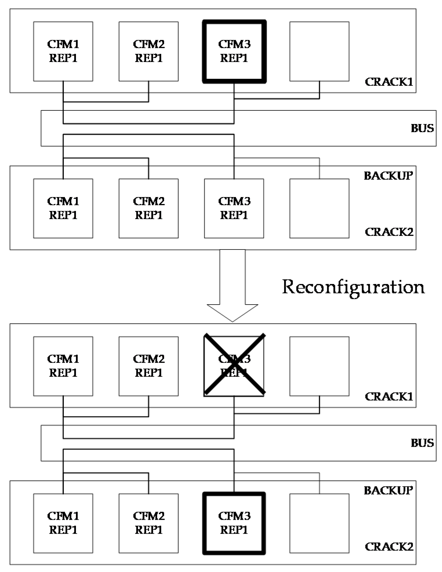
However, there are differences between the static and dynamic reconfigurations. Usually, the static reconfiguration system includes redundant modules. For example, CRACK2 is a redundant crack for CRACK1. Then, CFM3/REP2 is a backup for CFM3/REP1. When CFM3/REP1 fails, the applications run on CFM3 and can be transferred to REP2 from REP1, to make the system free from failure. The static reconfiguration of a system is presented in Figure 2.

2.1.3. Related Work for Dynamic Reconfiguration

Based on ARINC 653 [53], errors (fault) in IMA and response mechanisms are classified as shown in Table 1.
Therefore, when errors occur in IMA systems, the response mechanisms e.g., fault tolerance techniques, etc. will start to respond first. When the response mechanisms are unable to solve the error (fault), the error will trigger a dynamic reconfiguration. In this study, we aim to discuss and analyze the situations after the reconfiguration process starts, therefore, we assume it is not possible for response mechanisms to solve the fault, and that it has triggered the reconfiguration.
IMA dynamic reconfiguration occurs while the system is operating. In this study, the reconfiguration just pertains to the software, because hardware failure is irreversible [54]. IMA dynamic reconfiguration can change its tasks based on the requirement and recover rapidly from a failure [55]. This makes the system more flexible, and reduces hardware redundancy and the cost of unscheduled maintenance. Moreover, when a human is involved, the complexity of dynamic reconfiguration increases. Then, determining how to restrain the process to ensure its safety becomes a problem. Many researchers have explored the improvement of dynamic reconfiguration under all types of aspects.
Topping, C. [56] introduced a dynamically reconfigurable processing module (DRPM) for dynamic reconfiguration. The DRPM is made up of reprogrammable field programmable gate arrays (FPGAs), which is the basic hardware required for convenient reconfiguration. Suo [57] proposed that traditional analysis methods mostly focus on component failure. STPA is used to perform hazard analysis that focuses on human factors underlying the dynamic process. Temporal planners are proposed in [58], to plan the process of dynamic reconfiguration under stringent time and resource constraints. The preparation of a reconfiguration plan was difficult for most researchers in the past, due to the lack of automated and intelligent tools. They automated the dynamic reconfiguration by using artificial intelligence (AI) temporal planners to reduce its complexity. The AI planners conduct optimized task planning, which makes it difficult for humans to find out when a system is reconfigured. Montano [59] defined the elements in a dynamic reconfiguration in his thesis. A safety-critical manned systems (SCMS) dynamic reconfiguration is driven by an event to change functions or resources to meet the requirements of the operator. The thesis discusses automation and human involvement during the dynamic reconfiguration of a safety-critical system.
For the modeling of IMA dynamic reconfiguration, Zhang [60] proposed a reliability method based on AADL for IMA reconfiguration. The system was then translated to a Petri net for reliability analysis. The reliability calculation is for components of the system architecture. Suo introduced a method to address the real-time problems in the reconfiguration in another study [61]. The IMA system is also modeled using AADL. Then, the system is translated to TPN for verification.
Above all, the analysis for the dynamic reconfiguration process has not drawn much attention. This study proposed a method for analyzing the process, based on models to enhance the correctness, safety, and reliability of dynamic reconfiguration.

2.2. AADL

AADL is an effective modeling tool for analyzing real-time embedded systems and complex systems. In this study, AADL was employed to model the process of dynamic reconfiguration of IMA.

2.2.1. Components

Components are the core elements of a system. The components are divided into three sets—software, hardware, and composite. The configuration state of a system can be described by AADL. Moreover, the system structure and devices can be described. The software architecture of the IMA system is partitioned. Then, the logic configuration structure needs ARINC 653 annex in AADL. The ARINC 653 elements formed the system architecture and correspond to the AADL components [62].

2.2.2. Modes

A stable configuration state of the system during dynamic reconfiguration is represented by a mode. Modes can represent various states of a system or component, connections, and property value associations [63]. Mode transitions determine when the system is reconfigured dynamically to a new configuration. The textual and graphical representations of mode transition specifications for a simple example are shown in Figure 3.

2.2.3. Behavior Annex

Every state of a system and the detailed transitions are expressed by the behavior annex in AADL. The behavior annex defines the behavior specifications of the AADL components in a more refined than the core of the language. The behaviors described in this annex are based on state variables whose evolution is specified by transitions that can be characterized by conditions and actions [62].

2.3. Petri Net

AADL is widely used for modeling the embedded system. The AADL cannot perform the simulation analysis of the dynamic process visually. A Petri net is a compatible tool to conduct a simulation analysis.
A Petri net is a graphical and mathematical modeling tool for describing systems that are concurrent and asynchronous. Petri nets can not only simulate the dynamic activities or information transmission of a network, but also use mathematical models to govern the behavior of systems [64]. A Petri Net is described as a three-tuple P N = ( P , T , F ) [65], where P is a finite set of places; T is a finite set of transitions; F is a set of directed arcs. A classical Petri net comprises place, transitions, and arcs between places. The state of a system is usually described by a place. Transitions represent the changing process of systems. Arcs from a transition to a place, or from out of a place to a transition, have their weights. Tokens are present in each place to show the state of the place. Tokens are also used to represent data or resources. However, there are some shortcomings of a classical Petri net. A classical Petri net has no conception of time. Moreover, the description method of classical Petri nets is too single. Thus, there are many extensions and supplements for Petri nets. Some high-level Petri nets, such as CPNs and timed Petri nets, have been proposed.
CPNs are a high-level Petri nets used for designing, specification analysis, validation, and verification [66,67]. A CPN is a tuple C P N = ( Σ , P , T , A , N , C , G , E , I ) [68], where: Σ is a finite set of non-empty types, also called colour sets; P is a finite set of places; T is a finite set of transitions; A is a finite set of arcs; N is a node function; C is a color function; G is a guard function; E is an arc expression function; I is an initialization function. CPNs can describe the states of complex systems and state changes, due to triggering events. The feature of a CPN is that it provides a definition of color sets. A color set attached to a place has tokens in it. Each token should have a color. The guard of a transition needs to be satisfied before the transition is conducted. A CPN combines Petri nets and a programming language standard ML [69].
Recently, there have been some studies on model-based analysis approaches for dynamic reconfiguration. A reliability method based on AADL for IMA reconfiguration was proposed by Zhang [60]. The reliability calculation for components of the system is conducted after a model transition from AADL to Petri net. Suo [64] introduced a method modeled by AADL, and translated to TPN to address the real-time problems in the reconfiguration. Van der Aalst [70] pointed out that Petri nets not only are used as a design language for the specification of complex workflows, but also provide powerful analysis techniques to verify the correctness of workflow procedures. To the best of our knowledge, no analysis approach has focused on the dynamic reconfiguration process. In this study, a model-based analysis method for the process of dynamic reconfiguration was proposed to perform a hazard analysis.

3. Multi-Constraints for the Dynamic Reconfiguration Process

Here, a set of constraints was proposed for the IMA dynamic reconfiguration process. The constraints involve many aspects such as system states, real-time possibility, and resource ability. All the mentioned constraints were integrated into the analysis method, for checking the correctness of the design of IMA dynamic reconfiguration.

3.1. System State Constraints for Dynamic Reconfiguration

Before dynamic reconfiguration is triggered, some pre-checks of the modules in the system except the failure module should be conducted. If fault propagation has occurred, the initial setup strategy of dynamic reconfiguration should be abandoned. A new dynamic reconfiguration should be considered. A Boolean value S is set, to represent the initial state of the system. If the other modules of the system also fail after spreading, then S = 0. Thus, reconfiguration is terminated. If there is no spreading of the failure, the system can start reconfiguration, S = 1.

3.2. Real-Time Constraints for System State Transition

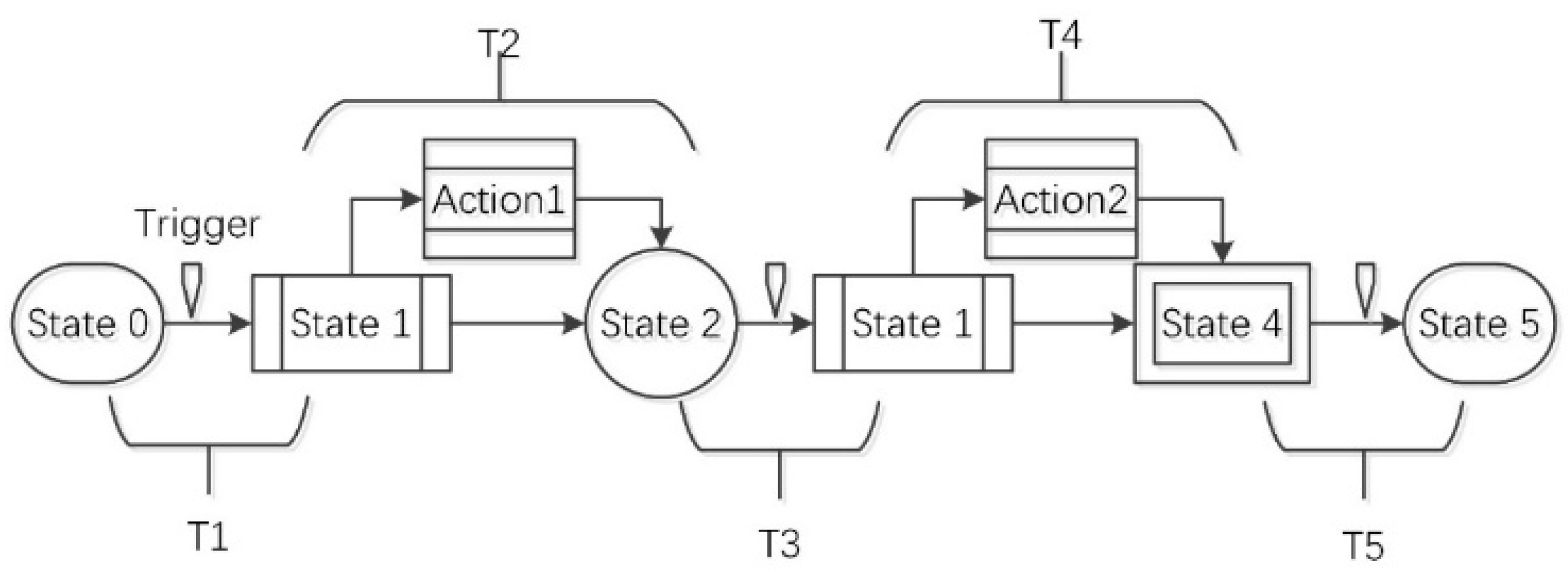
A brief introduction to the process of dynamic reconfiguration is conducted in Section 2. During the process, a system changes from one state to another, due to triggering events and actions. It is an important problem where the limits of time must be ensured. If the time between two states is very long, it affects the next state and causes some reconfiguration hazards. Analysis properties should be added in a model.
A time property is bonded to a transition from one state to the next state. To guarantee the time constraints, an algebraic equation that compares the sum of the time consumed by all the substates during the dynamic reconfiguration process with the limitation value was proposed.
Figure 4 presents that there are five states in a process. There is a trigger for transition between state 0 and state 1. The time for the transition is T 1 . There is an action costing time T 2 between state 1 and state 2. This is similar for the other states. Each action or transition between two states in the process is labeled with the time consumed T i . The limit time is t . Then, the total consuming time T s is the sum of T i . All the time satisfies Equation (1).
T S = T 1 + T 2 + + T n = i = 1 n T i
The behavior of dynamic reconfiguration should obey Equation (2):
T S t
By using this equation, a comparison between various time values can give us the result, whether the system can achieve the real-time constraint goals.

3.3. Memory Constraints for System State

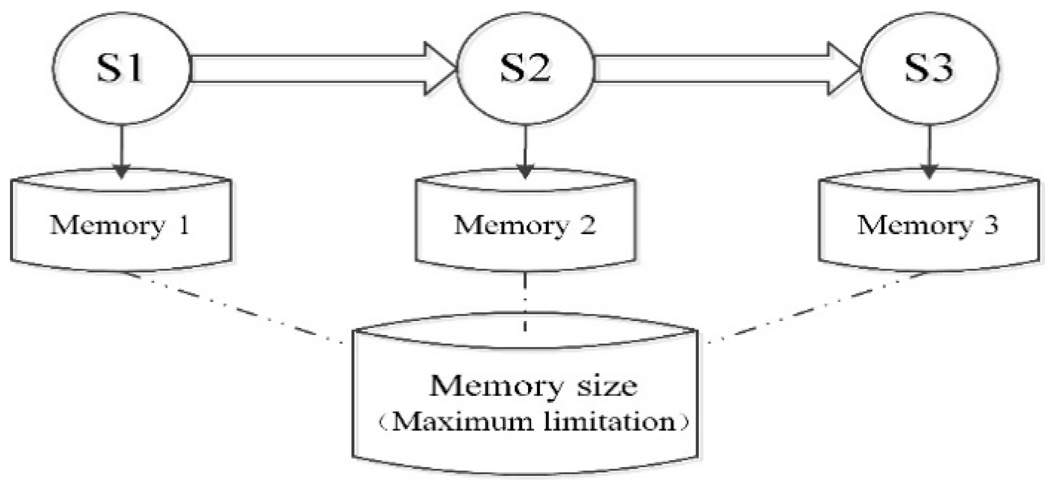
Similar to the time constraint, all the operations need their memory space, as shown in Figure 5. Obviously, the memory size allocated by each state during dynamic reconfiguration can be changed. The constraints of the memory size should be guaranteed, no matter how the demanding memory of substates changes.
Each state including the actions occupies memory M i . The maximum limitation of the memory size is m . Then, Equation (3) should be obeyed.
M i m ( i = 1 , 2 , n )

3.4. Ability Constraint for Sharing Data Resources

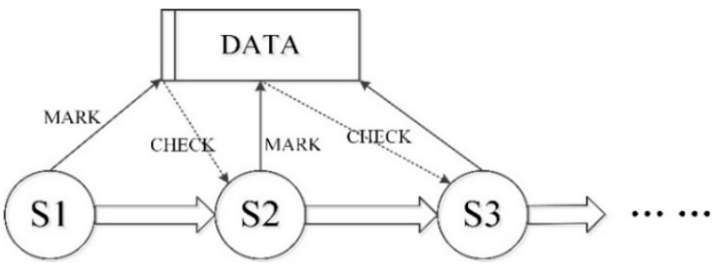
Under different modes of the system, the components of a system interact with the data components by reading and writing. The sharing of resources such as data should be marked with a serial number related to the time after operation in different states. If there is no mark on the data components after changing the data in state 1, then the system cannot decide whether the data is the result the system wants in state 2 after checking at the beginning of state 2. The absence of an operation in state 1 may stop the system from changing to the next state. This can be presented as Figure 6.
If the mark is correct, then the ability to share the resource (data) is verified appropriately. Assume that the sharing data component is marked with D i at a state i after each state. Then, M(Di) presents the serial number of D i . At the beginning of the next state, the D i of the data component is checked and the value is C ( D i + 1 ) .
The system needs to satisfy Equation (4).
M ( D i ) = C ( D i + 1 )
If Equation (4) is satisfied, it turns out that the data resource is operated correctly. Otherwise, there is something wrong or absent in the former state.

4. Model-Based Analysis Method

4.1. Modeling Approach Based on AADL

The complex process of dynamic reconfiguration is difficult to analyze without modeling. AADL is an effective modeling tool for a real-time embedded system. Dynamic reconfiguration is a process involved in a human operator and automation. The analysis range is quite wide. However, in this study, the events and conditions that change the process are simplified as some triggers. The object is just the process itself. Thus, a detailed decomposition and formalized expression of the simplified process is discussed here.

4.1.1. Dynamic Reconfiguration Process

When one or several failures occur on a module of IMA, a health manager detects the failure and informs a fault manager to handle it. The fault manager can handle a series of failures under all types of mechanism. Then, the fault manager determines the type of failure to take actions to solve it, for example, closing dynamic reconfiguration, or reporting to the upper layer manager.
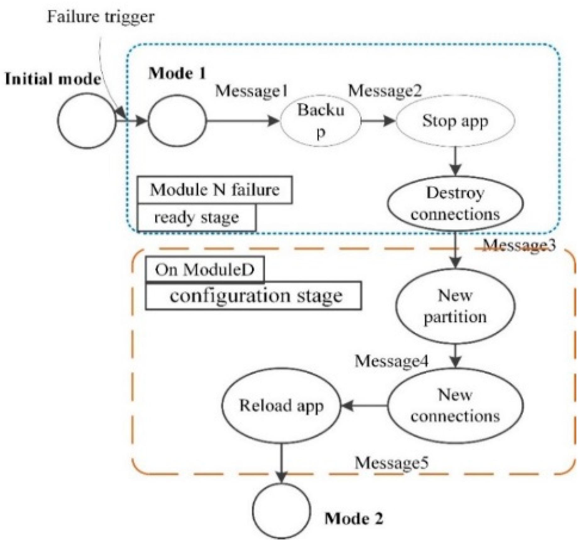
If it is unable for the fault manager to solve the failure, it will trigger dynamic reconfiguration. When the constraints are unsatisfied in the IMA dynamic reconfiguration process, the process will stop and the system will fail. When the dynamic reconfiguration process starts, the system stops the failure application and backs up the data. The connections are destroyed. Then, the target module of reconfiguration is selected, based on the functional and nonfunctional requirements, such as minimizing the cost of communication. The next step is to create a new partition on another module for the application. Subsequently, application reloading and connection rebuilding are conducted. In this study, the IMA dynamic reconfiguration process is described as serial flow diagrams, based on the assumption that the occurrence probability of each step of reconfiguration process is 100%. We aim to model the simulate the entire dynamic reconfiguration process, and analyze which steps and unsatisfied constraints leading reconfiguration process stop.
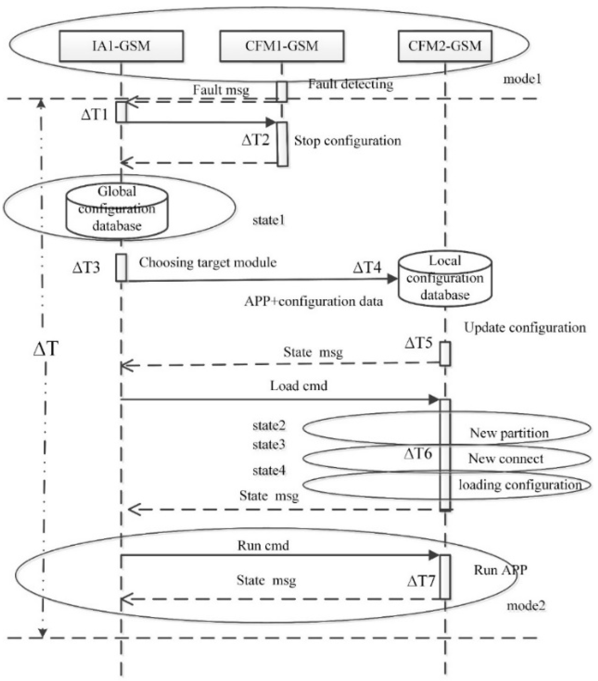
A typical process of dynamic reconfiguration is presented in Figure 7. The arrows indicate that messages are being sent during the process. Rectangles represent the important actions that occurred. Compared with the reconfiguration process mentioned in another study that always has redundant modules, dynamic reconfiguration discussed in this study refers to a system without spare modules, especially when reconfiguration in the case of redundancy is not designed, or is used in the system when dynamic reconfiguration begins.
The next part describes the method for modeling this process, followed by an interpretation of the model-based analysis method with these logic constraints.

4.1.2. Modeling of the Dynamic Reconfiguration Process

AADL is introduced above to describe the IMA system. A mode of a system can be associated with the logical configurations. Mode transitions imply that the configuration state changes from one to another [71]. A system or a component has different static structures and properties in different modes. A property can describe task scheduling, real-time characteristics, communication, memory, etc. Then, modes at the system level represent the content of a system configuration. A system has its own modules, partitions, processors, and communication bus in each mode. Thus, the static structure of the system in one mode is built by ARINC 653 annex in AADL.
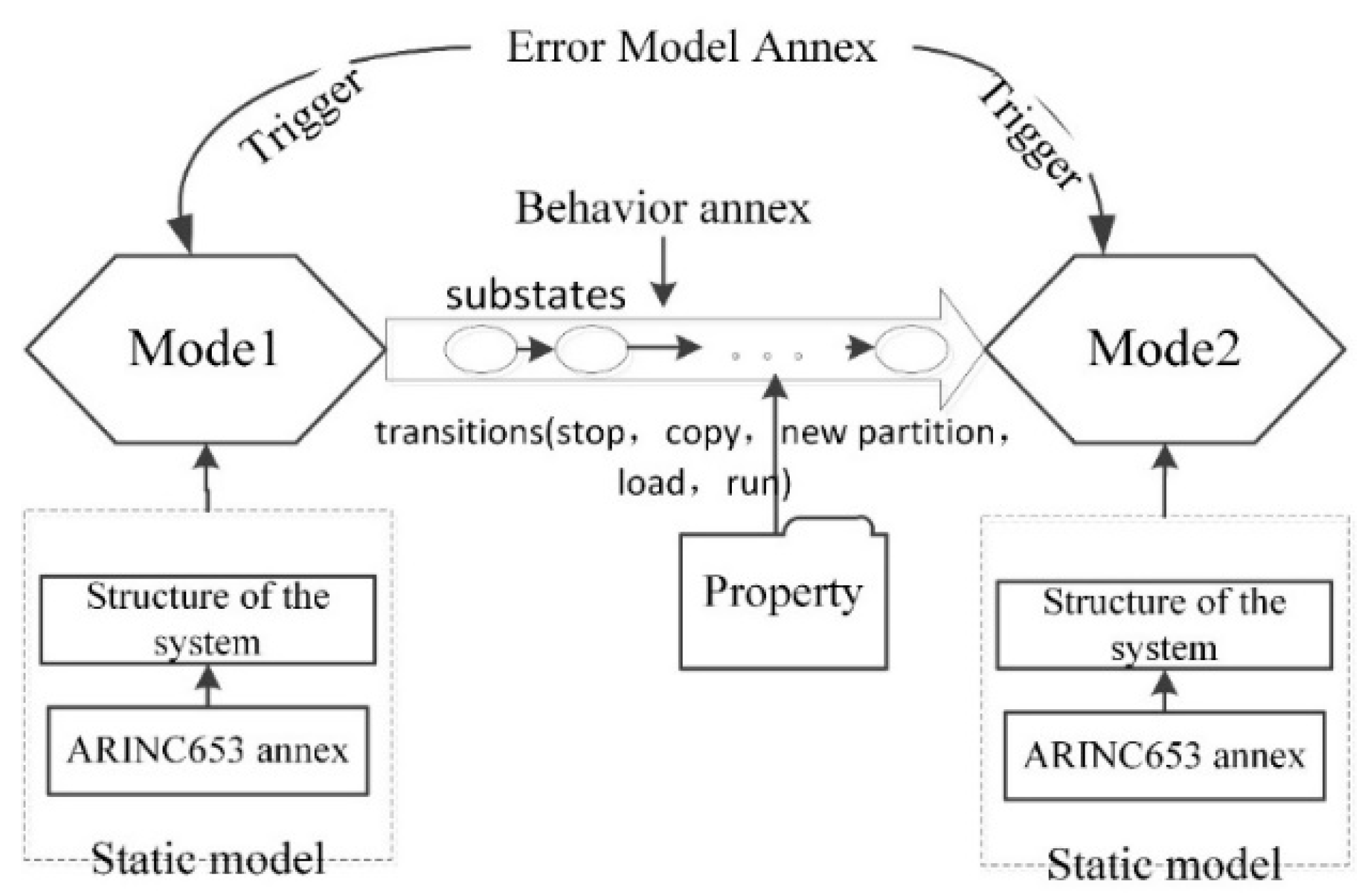
Figure 7 reveals a series of substates between two modes. The substates and transitions between the modes can be described in the behavior annex. The initial state in the annex corresponds with the prior mode, whereas the last complete state is the latter mode. Other substates can describe a definite state of the system when a transition is finished during the dynamic reconfiguration. The transition and action in the annex can describe the transition of the modes. The behavioral annex can describe the ceasing and restarting of applications, establishing and destroying processes and their threads, creation and deletion of communication interfaces, building and breaking of transfer connections and virtual channels, and sending and receiving messages with other GSM components.
The error model annex [62,72] represents triggering conditions in the reconfiguration caused by failures. An error model type may declare error states, error events, and error propagations. Error model implementations declare error state transitions. Transitions are declared to present the errors that are propagated out of a component based on the current error state of that component. An error property of a guard event may specify that certain patterns of error states and propagations are detected and cause an AADL core event, for example, triggering a mode transition.
The modeling method proposed in this study is presented in Figure 8. Mode change represents that dynamic reconfiguration occurred. More details and substates between the modes are described using the behavior annex. The trigger condition of the mode transition is declared in the error model annex.
Properties are added to the model, especially to the behavior annex for the following analysis. As the basis of the multi-constraint analysis, elements such as time properties, memory size, and data states are essential elements of the system.

4.2. Rules of Model Transformation

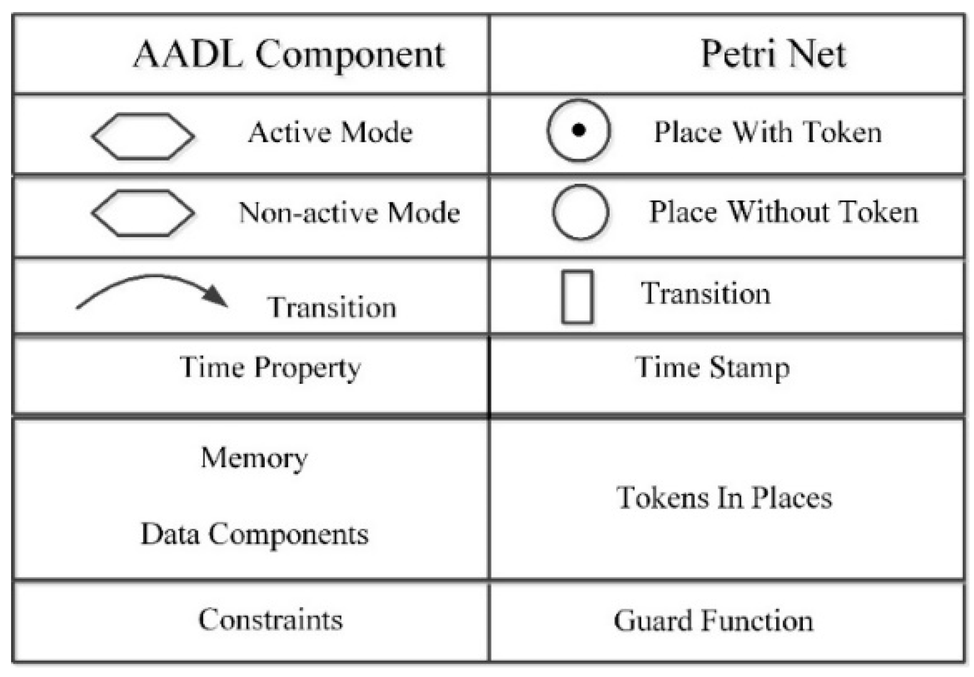
The AADL model of IMA dynamic reconfiguration is effective in describing the system structure and complex reconfiguration process. Some analysis can be conducted in tools for AADL, such as Open Source AADL Tool Environment (OSATE) [73]. However, automatic simulation and analysis are not the strong points of AADL, but fit for Petri net. Meanwhile, there are also disadvantages in modelling embedded systems for Petri nets. In this study, modes in AADL model could be presented by places in CPN. Active modes in AADL could be presented by place with specific color token in CPN. Transitions of modes in AADL model could be converted into transition of tokens in CPN. Time properties of the state transitions in AADL model correspond to time stamps of tokens in arcs in CPN. The resources such as memory and data in AADL model that are shared in the system can be represented by tokens in a place in CPN. Finally, the constraints about memory and time in AADL model can be converted to guard functions in a Petri net. Therefore, AADL model can be translated into CPN integrally as shown in Figure 9.

4.3. Simulation Analysis with CPN

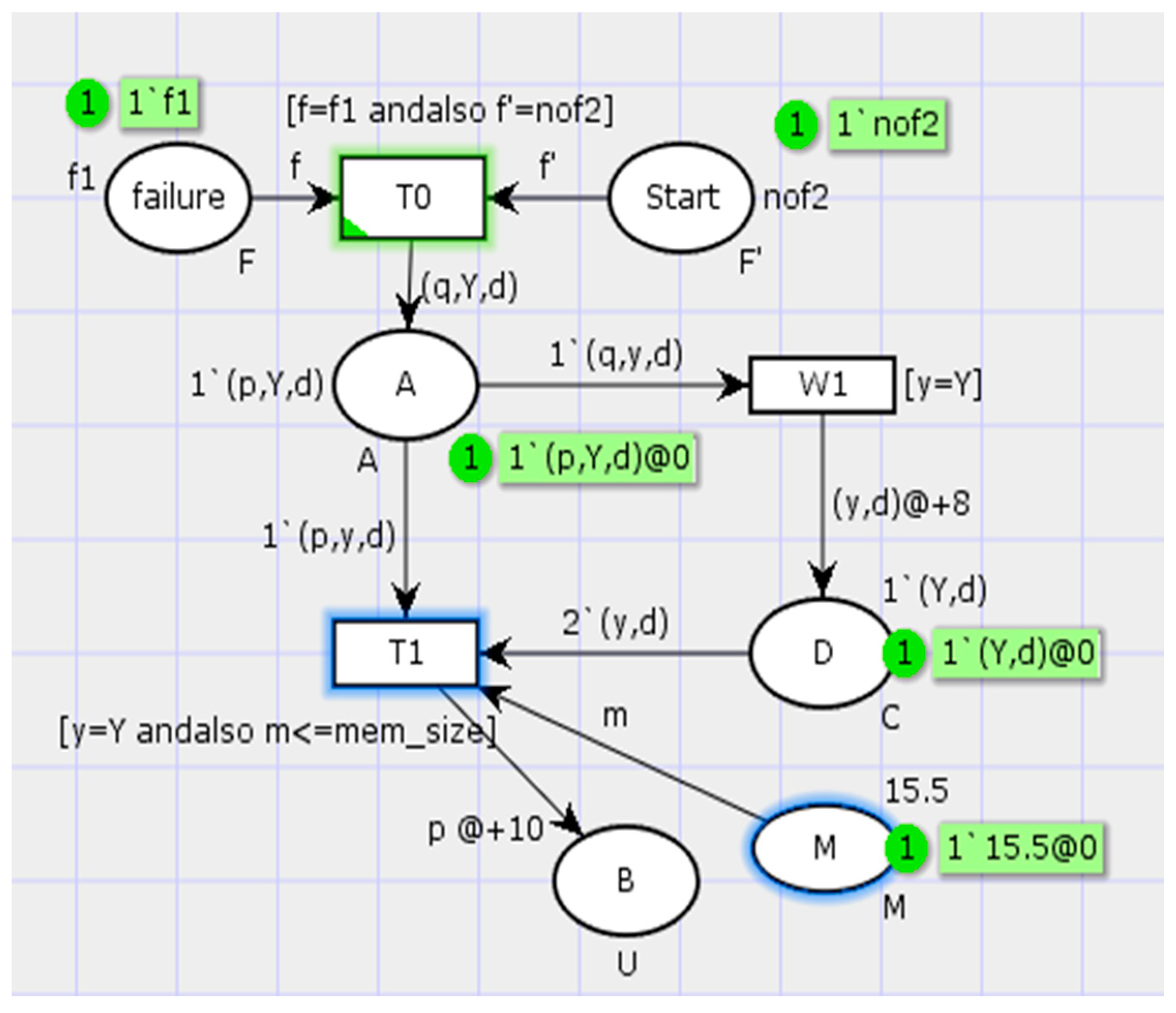
To clearly perform a demonstration on our CPN model based on the analysis method, a CPN example was employed. Intuitively, there is an example of a simple CPN shown in Figure 10. CPN tools [74] are employed to create a Petri nets. The example of the Petri net has six places. Three of the places represent the states of a system—start, A, and B. A place known as failure reveals a triggering event. A place denoted by D represents the data component. A place named as M represents the memory resource. The arc connects a place and a transition.
Different color sets are used to represent data writing, memory size, and state activity. The time stamp is used to represent the time consumed for a transition.
The declaration of this net is as follows: closet U = with p|q timed; closet W = with Y|N; closet D = with d; closet C = product W × D timed; closet F = with f1|nof1; closet S = with f2|nof2; var a:A; closet M = real with 1.0..30.0 timed; var x: U; var y:W; var m:M; var f’:F’; var f:F; val mem_size = 10.0. In the color set U, p is used to mark whether the place is activated, q means that the place A starts to write to the data component D, Y, or N means whether place A can write to the data. M represents the memory and T1 is used only if the M is in the limitation range. The color set F and F’ represent whether the failure event occurred, and whether the initial state of the system is affected.
After simulation with this Petri net, several types of results could be obtained based on the constraint conditions.
  • If all the constraints are fulfilled, the net is simulated to the last place and stops.
  • The system state for dynamic reconfiguration needs checking. The transition T0 can be fired only if the guard function [f = f1 and f’ = nof2] is satisfied. This implies that the failure event occurred for triggering dynamic reconfiguration and did not spread to affect the other modules of the system.
  • It should be determined whether the real-time constraints of the system state transition are satisfied or not. Every step in the simulation process is recorded by the time stamp in the transition. When one is step completed, the time consumed is compared with the real-time constraints. The result can tell us if the real-time constraints are met. There is a weakness in this constraint, in that the simulation must be operated manually step by step.
  • Memory constraints of system state do not meet the requirements. A guard function of T1 [y = Y and m ≤ mem_size] is set to define whether the memory size occupied in a state (the color set M) is less than the memory size limitation. In this net, the memory size limitation is 10 M, whereas 15.5 M is required in the process. Then, the net simulation ceases at T1 because it cannot be fired without meeting the guard function.
  • The ability constraint for sharing data resources is fulfilled. If the token from place A to transition W1 does not meet the guard function, the simulation stops. In this net, Y in color set W is sent to W1. The function [y = Y] is accomplished, and the simulation is continued. This means that a mark in demand is added on the data component (place D). The next state can be triggered with this mark.

5. Case Study

Here, in the case of the IMA system, a series of functional modules including navigation, display, communication, and integrated radio frequency sensors (IRFS) are integrated. The navigation module provides the place of the plane and guides the plane in a definition router. The module for an aircraft cockpit display provides the man–machine interface for a pilot. The communication module is responsible for the communication between an aircraft and a ground unit. IRFS integrates all the RF sensors in the aircraft for sending and receiving signals at all frequency ranges.

5.1. Modeling, Transformation, and Simulation

For simplification, an IMA system with four modules is modeled using the AADL in this section. We denote each module with the first letter of its name—navigation module (N), display module (D), communication (C), and IRFS (I). There are several partitions on each module according to their functions. An application runs on a partition. Process refers to the application here. Moreover, it is assumed that there is one partition in module N and module D. Three partitions are set up in module I. The other two partitions are in module C. The application on each partition communicates with GSM to define the operation of connections and applications.
First, the configuration state of a system can be described by AADL. The logic configuration structure needs the ARINC 653 annex in AADL. The ARINC 653 entities fabricated using the system architecture correspond to the AADL components, as introduced in Section 2. The model of the IMA system is presented in a graphical manner based on AADL, as shown in Figure 11.
When the module N fails, the GSM detects the failure and starts the failure management. In this case, the failure causes process 1 to break down and the system reconfiguration. Thus, dynamic reconfiguration is triggered.
(1)
After data backup for the process 1, process 1 is shut down and the connections of process 1 in the module N are destroyed.
(2)
The system selects a proper module to establish a new partition to run process 1. The strategy for selecting the target module is not introduced here. The target module is module D in this case.
(3)
A new partition is created in the target module D. Moreover, new channels and connections are set up. Process 1 is reloaded and restarted on the new partition in module D.
The process is presented in Figure 12.
In this case, a mode is used to represent a configuration state of the system during dynamic reconfiguration. The initial mode is the working state without failure of the system. When a failure occurs, the system changes to mode 1 and module N fails. After the reconfiguration, the system comes to mode 2. Thus, the system works in a new configuration without failure.
The mode transition of the system is revealed in Figure 13.
Behavior annex applied between two modes presents the mode transitions with a series of actions, triggers, and conditions, such as the data backup for process 1, and the creation of a new partition on module D, as presented in Figure 12. The properties defined are appended to the behavior annex. A modification is made to define the substates between mode 1 and mode 2. The declaration of the substate set is ‘composite state between mode 1 and mode 2 compstate.’ Then, each state in the compstate is defined as ‘mode 1: initial state, Backup: complete state, Stop_Process: complete state,’ and so on. A transition between the state Backup and Stop_Process is presented in the statement ‘Backup-[data_backup] - > Stop_Process; {RealtimeProperty: ProcessTime => 10.0; memory size ≥ 12 MB; }.’ Time and memory properties in this transition are appended to this transition.
The error model annex is used to represent triggering conditions caused by failures. In this case, one failure event occurs to cause the system to dynamic reconfiguration. The annex describes that the state of the system changes from the initial one without error to an error state. The statement is ‘error_free-[error_occurred] - > error_state.’ Then the transitions in the error model trigger the system to start reconfiguration. A statement can be ‘Error1_trigger ≥ self[detected_state] applies to mode_transition_event.’
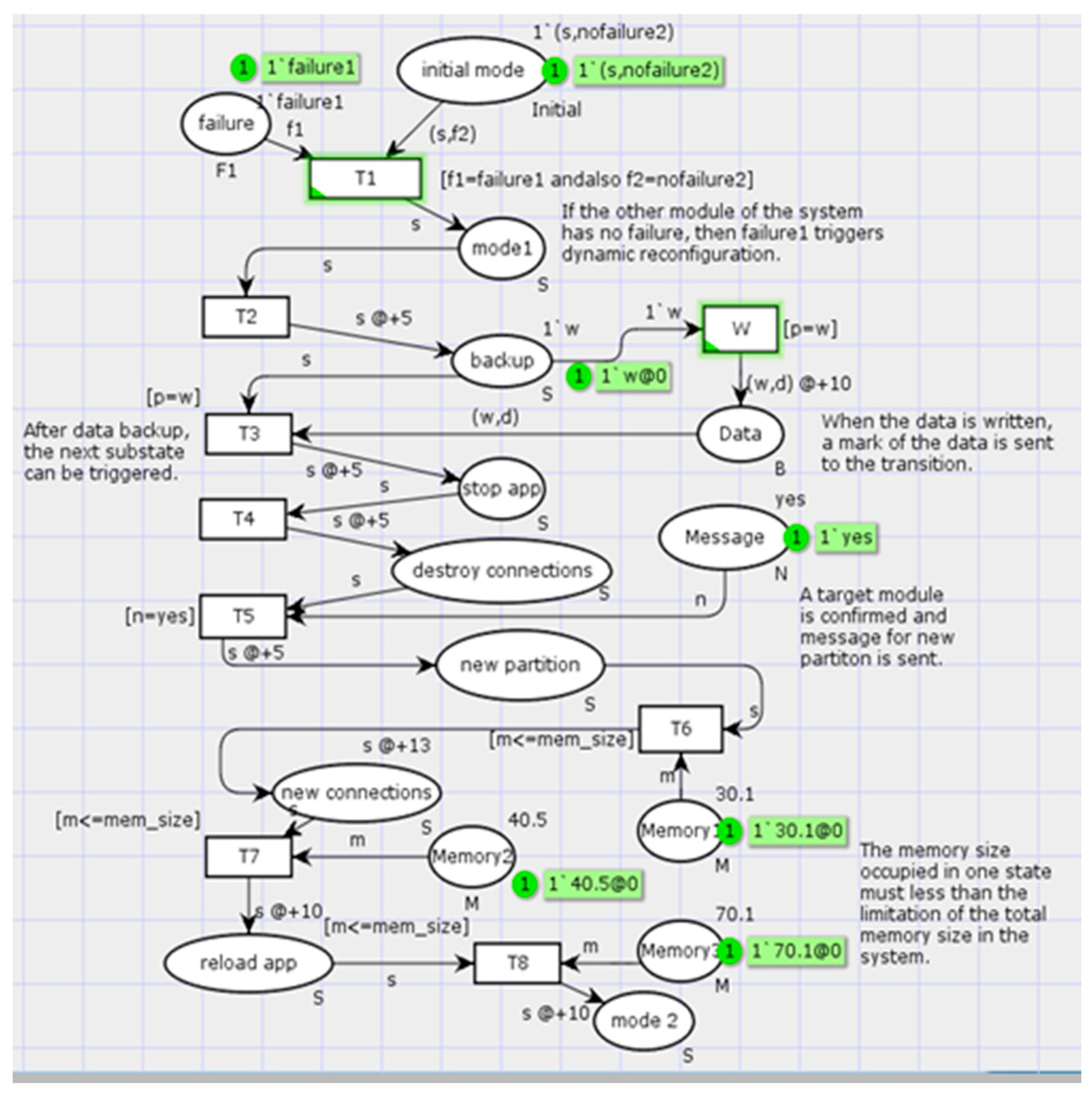
Based on the rules defined in Section 4, the AADL model of dynamic reconfiguration is converted to CPN. The modes and states of the behavior annex are converted to places in CPN. Mode transitions and behavior annex transitions are converted to transitions in the CPN. Other resources, such as memory and data, are represented by the color set of tokens in places. The triggering condition and constraints are added to the CPN as guard functions for a transition.
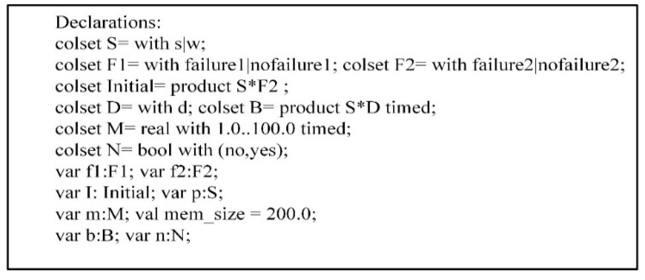
In this case, the system creates a new partition on module D that is defined as a substate in the behavior annex. Before the state is activated, the tokens pertaining to memory, and to convey the message that the former state is completed, should be sent to transition. Moreover, the guard function in the transition must be satisfied. For instance, the memory size needs to meet an inequation that the size in need should less than the size exists like Equation (3). The declarations for the CPN model are listed in Figure 14. The CPN model is presented in Figure 15.
The ‘s’ in the color set S is a token marking the state transition of the system. Color set F1 represents whether the failure event occurred, and F2 represents whether the initial state of the system is affected. Once the simulation is initiated, the net runs automatically step by step to send the colored tokens when the guard functions are satisfied.

5.2. Simulation Results

The results are listed in Table 2 after the simulation was conducted many times under different conditions. The precondition for each result was that the other constraint set in this net meets the requirements for finishing the simulation, except the condition pointed out in Table 2.
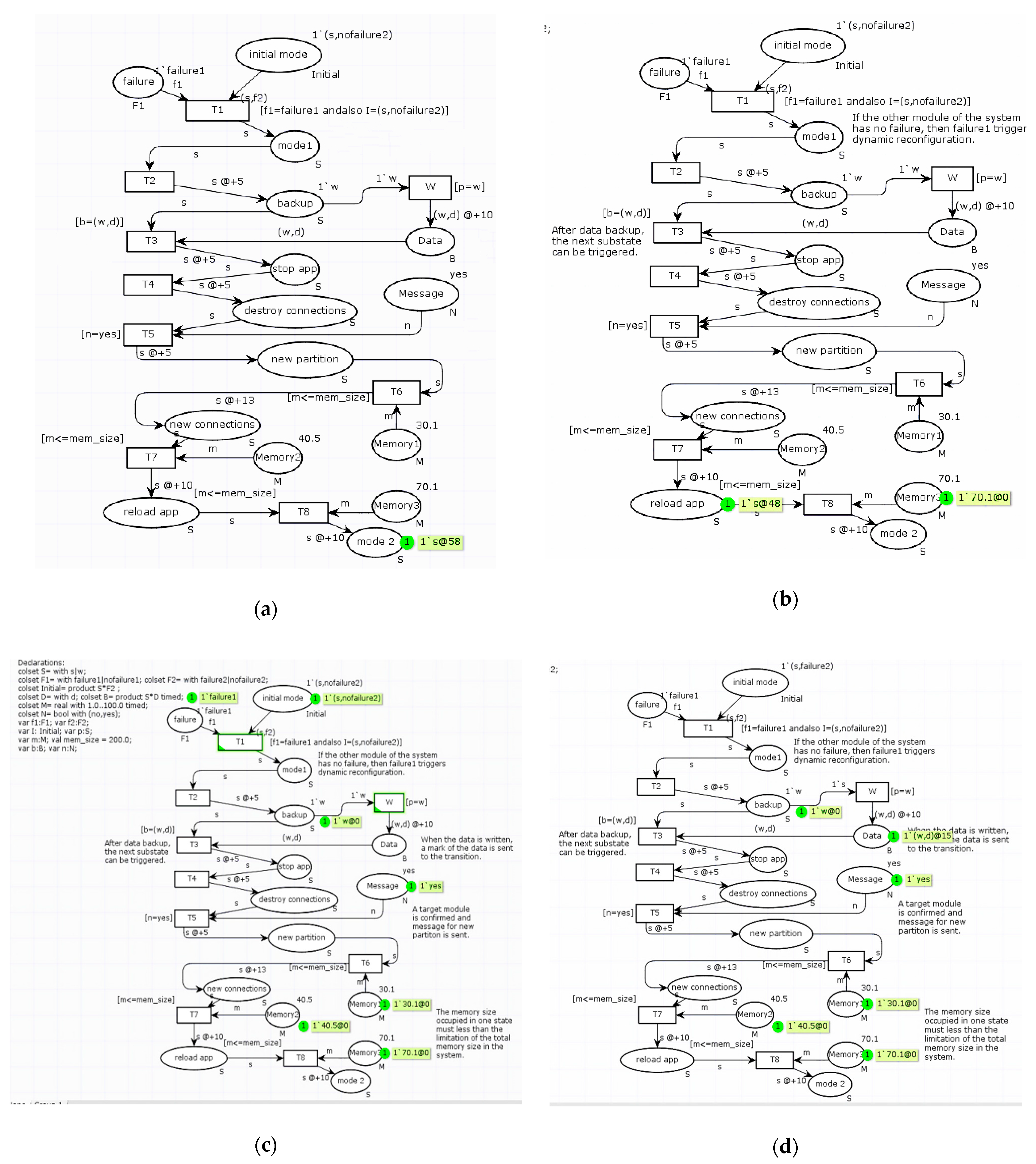
  • Condition 1: All the constraints are satisfied. The system model obtained when the simulation is conducted for 58 ms is shown in Figure 16a. This model is very similar to the original system model (Figure 15).
  • Condition 2: Constraint of the memory size is not satisfied. The simulation will stop running when it runs for 48 ms, because the guard function [m ≤ mem_size] is not satisfied. The upper limit of the system memory size mem_size is only 70 M, but the state needs to occupy a memory size of 70.1 M, so the simulation ends. The result is shown in Figure 16b.
  • Condition 3: Real-time constraint for the system state transition is not satisfied. By comparing the time consumed and real-time requirements, it can be shown whether the real-time constraint is satisfied.
  • Condition 4: System state constraint for dynamic reconfiguration is not satisfied. When the system runs to transition T1, it can be judged by the guard function [f1 = failure1 and also I = (s, nofailure2)]. If fault propagation occurs before system reconfiguration and other modules are affected, the reconfiguration scheme cannot be adopted. The reconfiguration process stops and cannot be conducted, as shown in Figure 16c.
  • Condition 5: Ability constraint for sharing data resources is not satisfied. When the system performs an operation of a shared data resource, if the forward state backup cannot write to the data component, then the checking of the data component and latter state are not triggered. Then, the process stops at a step of 15 ms, as shown in Figure 16d.

6. Conclusions

Existing studies on dynamic reconfiguration have rarely focused on the process hazard analysis. In this study, a new model-based analyzing method with multiple constraints for the IMA dynamic reconfiguration process was proposed, which is the main contribution of this study. The analysis method is conducted in three steps—modeling, model transition, and simulation. A new model method based on AADL was applied to model the dynamic reconfiguration process, and a transition turns the model to CPN for simulation. Several constraints concentrate on few different aspects for the simulation work. This approach was demonstrated using a four-module IMA system. The results of the case study showed the effectiveness of this method. The model-based analysis method with multiple constraints for the IMA dynamic reconfiguration process was proposed in this study, and helps to solve safety issues in the IMA dynamic reconfiguration caused by high integration and complexity.
In the future work, more constraints need to be supplemented for a more comprehensive analysis. If the system becomes more complex and the number of the state of dynamic reconfiguration explodes, it will be more difficult for the analysis work. A high workload occurs due to analysis. Thus, a tool for adding the constraining conditions automatically needs to be developed. The verification of this approach with more complex cases and engineering practices is required.

Author Contributions

Conceptualization, Z.J. and T.Z.; methodology, Z.J., S.W., and H.J.; formal analysis, Z.J., and H.J.; writing—original draft preparation, Z.J. and H.J.; writing—review and editing, Z.J. and S.W.; project administration, T.Z.; funding acquisition, T.Z. and S.W. All authors have read and agreed to the published version of the manuscript.

Funding

This work was supported by Foundation of No.61400020404.

Conflicts of Interest

The authors declare that there is no conflict of interest.

References

  1. Airlines Electronic Engineering Committee. Avionics Application Software Standard Interface Part 1-Required Services; ARINC Document ARINC Specification 653 P1-3; Aeronautical Radio, Inc.: Annapolis, MD, USA, 2010. [Google Scholar]
  2. Standardization Agreement (STANAG), North Atlantic Treaty Organization (NATO). 4626-2005 Modular and Open Avionics Architecture (Part I: Architecture); North Atlantic Treaty Organization: Brussels, Belgium, 2005; pp. 24–34. [Google Scholar]
  3. Jolliffe, G. Producing a safety case for IMA blueprints. In Proceedings of the 24th Digital Avionics Systems Conference, Washington, DC, USA, 30 October–3 November 2005; IEEE: Piscataway, NJ, USA, 2005; Volume 2. [Google Scholar]
  4. López-Jaquero, V.; Montero, F.; Navarro, E.; Esparcia, A.; Catal’n, J.A. Supporting ARINC 653-based dynamic reconfiguration. In Proceedings of the 2012 Joint Working IEEE/IFIP Conference on Software Architecture and European Conference on Software Architecture, Helsinki, Finland, 20–24 August 2012; IEEE: Piscataway, NJ, USA, 2012. [Google Scholar]
  5. Bieber, P.; Noulard, E.; Pagetti, C.; Planche, T.; Vialard, F. Preliminary design of future reconfigurable IMA platforms. ACM Sigbed Rev. 2009, 6, 1–5. [Google Scholar] [CrossRef]
  6. Hilbrich, R.; van Kampenhout, R. Dynamic reconfiguration in NoC-based MPSoCs in the avionics domain. In Proceedings of the 3rd International Workshop on Multicore Software Engineering, ACM, New York, NY, USA, 1–8 May 2010. [Google Scholar]
  7. Ding, M. Research on Reconfiguration and Verification Methods for Integrated Modular Avionics. Ph.D. Thesis, Northwest University, Xi’an, China, 2019. [Google Scholar]
  8. Shukla, J.; Das, B.; Pant, V. Stability constrained optimal distribution system reconfiguration considering uncertainties in correlated loads and distributed generations. Int. J. Electr. Power 2018, 99, 121–133. [Google Scholar] [CrossRef]
  9. Ellis, S.M. Dynamic software reconfiguration for fault-tolerant real-time avionic systems. Microprocess. Microsyst. 1997, 21, 29–39. [Google Scholar] [CrossRef]
  10. van Vliet, J.C. Software Engineering-Principles and Practice, 3rd ed.; Wiley: Hoboken, NJ, USA, 2008. [Google Scholar]
  11. SAE. AS5506A: Architecture Analysis and Design Language (AADL) Version 2.0; SAE: Warrendale, PA, USA, 2009. [Google Scholar]
  12. SAE. AS5506 Annex: Behavior Specification V2.0; SAE: Warrendale, PA, USA, 2011. [Google Scholar]
  13. Yang, Z.; Hu, K.; Ma, D.; Bodeveix, J.; Pi, L.; Talpin, J. From AADL to timed abstract state machines: A verified model transformation. J. Syst. Softw. 2014, 93, 42–68. [Google Scholar] [CrossRef] [Green Version]
  14. Walker, M.; Reiser, M.O.; Tucci-Piergiovanni, S.; Papadopoulos, Y.; Lönn, H.; Mraidha, C.; Parker, D.; Chen, D.; Servat, D. Automatic optimisation of system architectures using EAST-ADL. Syst. Softw. 2013, 86, 2467–2487. [Google Scholar] [CrossRef] [Green Version]
  15. Feiler, P.H.; Gluch, D.P. Model-Based Engineering with AADL: An introduction to the SAE Architecture Analysis & Design Language; Addison-Wesley: Boston, MA, USA, 2012. [Google Scholar]
  16. Bozzano, M.; Cimatti, A.; Katoen, J.P.; Nguyen, V.Y.; Noll, T.; Roveri, M. Safety, dependability and performance analysis of extended AADL models. Comput. J. 2010, 54, 754–775. [Google Scholar] [CrossRef]
  17. Hugues, J.; Zalila, B.; Pautet, L.; Kordon, F. From the prototype to the final embedded system using the Ocarina AADL tool suite. ACM Trans. Embed. Comput. Syst. (TECS) 2008, 7, 42. [Google Scholar]
  18. Chkouri, M.Y.; Robert, A.; Bozga, M.; Sifakis, J. Translating AADL into BIP-application to the verification of real-time systems. In Proceedings of the International Conference on Model Driven Engineering Languages and Systems, Toulouse, France, 28 September–3 October 2008; Springer: Berlin/Heidelberg, Germany, 2008. [Google Scholar]
  19. Zhang, F.; Zhao, Y.; Ma, D.; Niu, W. Formal verification of behavioral AADL models by stateful timed CSP. IEEE Access 2017, 5, 27421–27438. [Google Scholar] [CrossRef]
  20. Zhao, Z.; Zhang, J.; Sun, Y.; Liu, Z. Modeling of Avionic Display System for Civil Aircraft Based on AADL, 2018; IEEE: Piscataway, NJ, USA, 2018; pp. 4121–4126. [Google Scholar]
  21. Liu, Z.; Zhao, Z. Modeling and Schedulability Verfication of IMA Partitioning Based on AADL, 2017; IEEE: Piscataway, NJ, USA, 2017; pp. 417–420. [Google Scholar]
  22. Liu, W. AADL Model Transformation and Verification. Master’s Thesis, Shaanxi Normal University, Xi’an, China, 2013. [Google Scholar]
  23. Wu, Y.; Li, S. AADL model based on TPN. Comput. Technol. Dev. 2014, 24, 88–91. [Google Scholar]
  24. Hadad, A.S.A.; Ma, C.; Ahmed, A.A.O. Formal Verification of AADL Models by Event-B. IEEE Access 2020, 8, 72814–72834. [Google Scholar] [CrossRef]
  25. Sendall, S.; Kozaczynski, W. Model transformation: The heart and soul of model-driven software development. IEEE Softw. 2003, 20, 42–45. [Google Scholar] [CrossRef]
  26. Cuadrado, J.S.; Guerra, E.; de Lara, J. Static analysis of model transformations. IEEE Trans. Softw. Eng. 2017, 43, 868–897. [Google Scholar] [CrossRef]
  27. Hu, K.; Zhang, T.; Yang, Z.; Tsai, W. Exploring AADL verification tool through model transformation. J. Syst. Architect. 2015, 61, 141–156. [Google Scholar] [CrossRef] [Green Version]
  28. Chkouri, M.Y.; Robert, A.; Bozga, M.; Sifakis, J. Translating AADL into BIPapplication to the Verification of Real-Time Systems, Models in Software Engineering; Springer: Berlin/Heidelberg, Germany, 2009; pp. 5–19. [Google Scholar]
  29. Berthomieu, B.; Bodeveix, J.P.; Chaudet, C.; Dal Zilio, S.; Filali, M.; Vernadat, F. Formal Verification of AADL Specifications in the Topcased Environment, Reliable Software Technologies–Ada-Europe 2009; Springer: Berlin/Heidelberg, Germany, 2009; pp. 207–221. [Google Scholar]
  30. Rugina, A.-E.; Kanoun, K.; Kaâniche, M. A System Dependability Modeling Framework Using AADL and GSPNs, Architecting Dependable Systems IV; Springer: Berlin/Heidelberg, Germany, 2007; pp. 14–38. [Google Scholar]
  31. Bozzano, M.; Cavada, R.; Cimatti, A.; Katoen, J.-P.; Nguyen, V.Y.; Noll, T.; Olive, X. Formal verification and validation of AADL models. In Proceedings of the Embedded Real-Time Software and Systems 2010 (ERTS 2010), Toulouse, France, 19–21 May 2010. [Google Scholar]
  32. Kabir, S.; Papadopoulos, Y. Applications of Bayesian networks and Petri nets in safety, reliability, and risk assessments: A review. Saf. Sci. 2019, 115, 154–175. [Google Scholar] [CrossRef]
  33. Luan, W.; Qi, L.; Zhao, Z.; Liu, J.; Du, Y. Logic Petri net synthesis for cooperative systems. IEEE Access 2019, 7, 161937–161948. [Google Scholar] [CrossRef]
  34. Jensen, K. Coloured Petri Nets. In Petri Nets: Central Models and Their Properties; Springer: Berlin/Heidelberg, Germany, 1987; pp. 248–299. [Google Scholar]
  35. Jensen, K. Coloured Petri Nets: Basic Concepts, Analysis Methods and Practical Use; Springer Science & Business Media: Berlin, Germany, 2013; Volume 1. [Google Scholar]
  36. Huber, P.; Jensen, K.; Shapiro, R.M. Hierarchies in coloured Petri nets. In Proceedings of the International Conference on Application and Theory of Petri Nets, Bratislava, Slovakia, 24–29 June 2018; Springer: Berlin/Heidelberg, Germany, 1989. [Google Scholar]
  37. Marsan, M.A.; Balbo, G.; Conte, G.; Donatelli, S.; Franceschinis, G. Modelling with Generalized Stochastic Petri Nets; John Wiley & Sons, Inc.: Hoboken, NJ, USA, 1994. [Google Scholar]
  38. Ajmone Marsan, M.; Conte, G.; Balbo, G. A class of generalized stochastic Petri nets for the performance evaluation of multiprocessor systems. ACM Trans. Comput. Syst. (TOCS) 1984, 2, 93–122. [Google Scholar] [CrossRef]
  39. Chiola, G.; Marsan, M.A.; Balbo, G.; Conte, G. Generalized stochastic Petri nets: A definition at the net level and its implications. IEEE Trans. Softw. Eng. 1993, 19, 89–107. [Google Scholar] [CrossRef]
  40. Bugarin, A.J.; Barro, S. Fuzzy reasoning supported by Petri nets. IEEE Trans. Fuzzy Syst. 1994, 2, 135–150. [Google Scholar] [CrossRef]
  41. Li, Y.; Chen, Y.; Tang, N.; Yang, L. Modeling and analysis of failure mechanism dependence based on petri net. In Proceedings of the Prognostics and System Health Management Conference, Chengdu, China, 19–21 October 2016; pp. 1–7. [Google Scholar]
  42. Wieland, C.; Schmid, O.; Meiler, M.; Wachtel, A.; Linsler, D. Reliability computing of polymer-electrolyte-membrane fuel cell stacks through petri nets. J. Power Sources 2009, 190, 34–39. [Google Scholar] [CrossRef]
  43. Sunanda, B.E.; Seetharamaiah, P. Modeling of safety-critical systems using petri nets. ACM SIGSOFT Softw. Eng. Notes 2015, 40, 1–7. [Google Scholar] [CrossRef]
  44. Li, W.; He, M.; Sun, Y.; Cao, Q. A novel layered fuzzy Petri nets modelling and reasoning method for process equipment failure risk assessment. J. Loss Prevent. Proc. 2019, 62, 103953. [Google Scholar] [CrossRef]
  45. Gonçalves, P.; Sobral, J.; Ferreira, L.A. Unmanned aerial vehicle safety assessment modelling through petri Nets. Reliab. Eng. Syst. Safe 2017, 167, 383–393. [Google Scholar] [CrossRef]
  46. Liu, R. Reliability Modeling of Integrated Modular Avionics System Platform Using AADL, and GSPN Analysis Method. Master’s Thesis, Civil Aviation University of China, Tianjin, China, 2016. [Google Scholar]
  47. Li, Z.; Wang, S.; Zhao, T.; Liu, B. A hazard analysis via an improved timed colored petri net with time–space coupling safety constraint. Chin. J. Aeronaut. 2016, 29, 1027–1041. [Google Scholar] [CrossRef] [Green Version]
  48. Arena, D.; Criscione, F.; Trapani, N. Risk assessment in a chemical plant with a CPN-HAZOP Tool. IFAC-PapersOnLine 2018, 51, 939–944. [Google Scholar] [CrossRef]
  49. Committee, A.E. ARINC 664 Aircraft Data Networks, Part7: Avionics Full Duplex Switched Ethernet (AFDX) Network; Aeronautical Radio, Inc.: Annapolis, MD, USA, 2005. [Google Scholar]
  50. Prisaznuk, P.J. ARINC 653 role in integrated modular avionics (IMA). In Proceedings of the 2008 IEEE/AIAA 27th Digital Avionics Systems Conference, St. Paul, MN, USA, 26–30 October 2008; IEEE: Piscataway, NJ, USA, 2008. [Google Scholar]
  51. Zhang, F.; Chu, W.; Fan, X.; Wan, M. Research on architecture of integrated modular avionics [J]. Electron. Opt. Control 2009, 9, 013. [Google Scholar]
  52. Reis, J.G.; Wanner, L.; Fröhlich, A.A. A framework for dynamic real-time reconfiguration. In Proceedings of the 2015 Euromicro Conference on Digital System Design (DSD), Funchal, Portugal, 26–28 August 2015; IEEE: Piscataway, NJ, USA, 2015. [Google Scholar]
  53. Aeronautical Radio. Avionics Application Software Standard Interface; ARINC653: Annapolis, MD, USA, 2010. [Google Scholar]
  54. Montano, G.; McDermid, J. Human Involvement in Dynamic Reconfiguration of Integrated Modular Avionics, Avionics. In Proceedings of the 27th Digital Avionics Systems Conference, St. Paul, MN, USA, 26–30 October 2008; IEEE: Piscataway, NJ, USA, 2008. [Google Scholar]
  55. Zhou, Q.; Gu, T.; Hong, R.; Wang, S. An AADL-based design for dynamic reconfiguration of DIMA. In Proceedings of the 2013 IEEE/AIAA 32nd Digital Avionics Systems Conference (DASC), East Syracuse, NY, USA, 5–10 October 2013; IEEE: Piscataway, NJ, USA, 2013. [Google Scholar]
  56. Montano, G.; Norridge, P.; Sullivan, W.; Topping, C.; Wishart, A.; Bubenhagen, F.; Fiethe, B.; Michalik, H.; Osterloh, B.; Ilstad, J. Dynamically Reconfigurable Processing Module for Future Space Applications. In Proceedings of the DASIA 2010 Data Systems In Aerospace, Budapest, Hungary, 1–4 June 2010; Volume 682. [Google Scholar]
  57. Suo, D.; An, J.; Zhu, J. A new approach to improve safety of reconfiguration in integrated modular avionics. In Proceedings of the 2011 IEEE/AIAA 30th Digital Avionics Systems Conference (DASC), Seattle, WA, USA, 16–20 October 2011; IEEE: Piscataway, NJ, USA, 2011. [Google Scholar]
  58. Arshad, N. Dynamic Reconfiguration of Software Systems Using Temporal Planning. Ph.D. Thesis, University of Colourado, Boulder, CO, USA, 2003. [Google Scholar]
  59. Montano, G. Dynamic Reconfiguration of Safety-Critical Systems: Automation and Human Involvement. Ph.D. Thesis, University of York, York, UK, 2011. [Google Scholar]
  60. Quan, Z.; Wang, S. IMA reconfiguration modelling and reliability analysis based on AADL. In Proceedings of the 4th Annual IEEE International Conference on Cyber Technology in Automation, Control and Intelligent, Hong Kong, China, 4–7 June 2014; IEEE: Piscataway, NJ, USA, 2014. [Google Scholar]
  61. Suo, D.; An, J.; Zhu, J. AADL-based modelling and TPN-based verification of reconfiguration in integrated modular avionics. In Proceedings of the 2011 18th Asia Pacific Software Engineering Conference (APSEC), Ho Chi Minh, Vietnam, 5–8 December 2011; IEEE: Piscataway, NJ, USA, 2011. [Google Scholar]
  62. Aerospace, S.A.E. SAE Architecture Analysis and Design Language (AADL); Society of Automotive Engineers (SAE) International: Houston, TX, USA, 2009. [Google Scholar]
  63. Feiler, P.H.; Gluch, D.P.; Hudak, J.J. The Architecture Analysis & Design Language (AADL): An Introduction; No. CMU/SEI-2006-TN-011; Carnegie-Mellon Univ Pittsburgh PA Software Engineering Inst: Pittsburgh, PA, USA, 2006. [Google Scholar]
  64. Murata, T. Petri nets: Properties, analysis and applications. Proc. IEEE 1989, 77, 541–580. [Google Scholar] [CrossRef]
  65. Petri, C.A. Kommunikation mit Automaten. Bonn: Institute fur Instrumentelle Mathematik, Schriften des IIM Nr.3, 1962. Also, English Translation: Communication with Automata. Tech. Rep. RADC-TR-65–377 1966, 1, 253–279. [Google Scholar]
  66. Jensen, K. Coloured Petri nets: A high level language for system design and analysis. In Proceedings of the International Conference on Application and Theory of Petri Nets, Bonn, Germany, 1–5 June 1989; Springer: Berlin/Heidelberg, Germany, 1989. [Google Scholar]
  67. Kristensen, L.M.; Christensen, S.; Jensen, K. The practitioner’s guide to coloured Petri nets. Int. J. Softw. Tools Technol. Transf. (STTT) 1998, 2, 98–132. [Google Scholar] [CrossRef]
  68. Jensen, K.; Munkegade, N. An introduction to the theoretical aspects of coloured Petri nets. In Lecture Notes in Computer Science; Springer: Berlin/Heidelberg, Germany, 1994; Volume 803. [Google Scholar]
  69. Jensen, K.; Kristensen, L.M.; Wells, L. Coloured Petri Nets and CPN Tools for modelling and validation of concurrent systems. Int. J. Softw. Tools Technol. Transf. 2007, 9, 213–254. [Google Scholar] [CrossRef]
  70. Van der Aalst, W.M. The application of Petri nets to workflow management. J. Circuits Syst. Comput. 1998, 8, 21–66. [Google Scholar] [CrossRef] [Green Version]
  71. STANAG, NATO. 4626-2005 Modular and Open Avionics Architecture (Part VI: Guidelines for System Issues); Volume 4: System Configuration/Reconfiguration page: 7–20; North Atlantic Organization: Brussels, Belgium, 2005. [Google Scholar]
  72. Feiler, P.H.; Lewis, B.A.; Vestal, S. The SAE Architecture Analysis & Design Language (AADL) a standard for engineering performance critical systems. In Proceedings of the 2006 IEEE Conference on Computer Aided Control System Design, 2006 IEEE International Conference on Control Applications, 2006 IEEE International Symposium on Intelligent Control, Munich, Germany, 4–6 October 2006; IEEE: Piscataway, NJ, USA, 2006. [Google Scholar]
  73. SEI AADL Team. An Extensible Open Source AADL Tool Environment (OSATE); Software Engineering Institute: Pittsburgh, PA, USA, 2006. [Google Scholar]
  74. Beaudouin-Lafon, M.; Mackay, W.E.; Jensen, M.; Andersen, P.; Janecek, P.; Lassen, M.; Lund, K.; Mortensen, K.; Munck, S.; Ratzer, A.; et al. CPN/Tools: A tool for editing and simulating coloured petri nets ETAPS tool demonstration related to TACAS. In Proceedings of the International Conference on Tools and Algorithms for the Construction and Analysis of Systems, Genova, Italy, 2–6 April 2001; Springer: Berlin/Heidelberg, Germany, 2001. [Google Scholar]
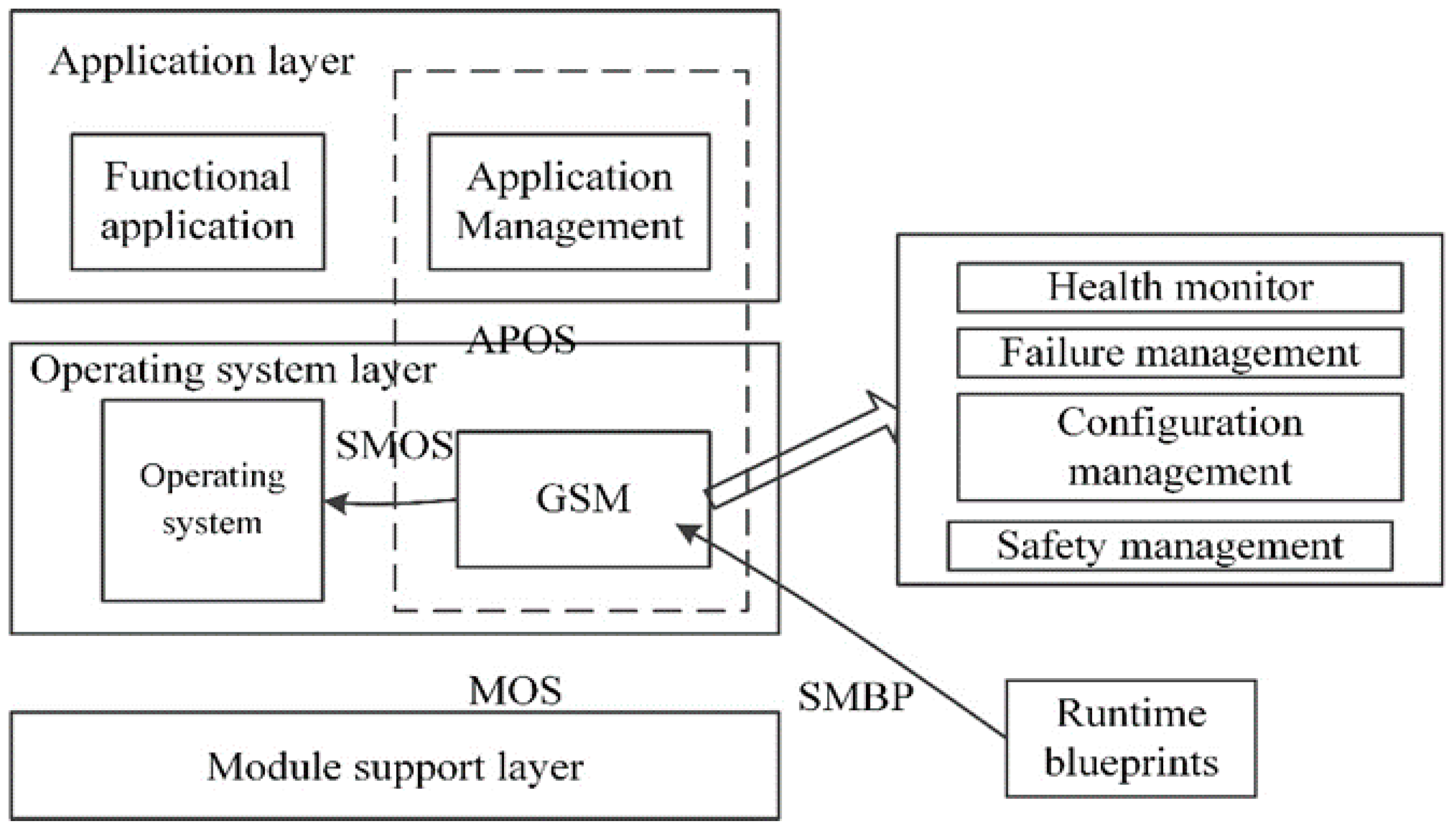
Figure 1. Integrated modular avionics (IMA) software architecture.
Processes 08 00574 g001
Figure 2. System reconfiguration with redundant modules.
Processes 08 00574 g002
Figure 3. Mode transition.
Processes 08 00574 g003
Figure 4. Time for the state transition of a system.
Processes 08 00574 g004
Figure 5. Memory for the system state.
Processes 08 00574 g005
Figure 6. Data sharing by different states.
Processes 08 00574 g006
Figure 7. A typical process of dynamic reconfiguration.
Processes 08 00574 g007
Figure 8. IMA Dynamic Reconfiguration Modelling Approach.
Processes 08 00574 g008
Figure 9. The relationship of model transformation between Architecture Analysis & Design Language (AADL) and colored Petri net (CPN).
Processes 08 00574 g009
Figure 10. A CPN example.
Processes 08 00574 g010
Figure 11. Model of system structure in one mode based on AADL.
Processes 08 00574 g011
Figure 12. A case of decomposition of dynamic reconfiguration.
Processes 08 00574 g012
Figure 13. Mode transition of the dynamic reconfiguration of IMA.
Processes 08 00574 g013
Figure 14. Declaration for the CPN case.
Processes 08 00574 g014
Figure 15. A CPN model for the dynamic reconfiguration.
Processes 08 00574 g015
Figure 16. (a) System model in the condition that all the constraints are satisfied. (b) System model in the condition that constraint of memory size is not satisfied. (c) System model in the condition that system state constraint for the dynamic reconfiguration is not satisfied. (d) System model in the condition that ability constraint for sharing data resources is not satisfied.
Processes 08 00574 g016
Table 1. Error classification and response mechanisms.
Error LevelExamples of ErrorsResponse Mechanism
Module Level
  • Application error raised by an application process
  • Illegal O/S request
  • Process execution errors (overflow, memory violation, etc.)
  • Ignore
  • Shutdown the module
  • Reset the module
  • Recovery Actions defined by the implementation
Partition Level
  • Partition configuration table error during partition initialization
  • Partition initialization error
  • Errors that occur during process management
  • Errors that occur during error handler process
  • Ignore
  • Stop the partition (IDLE)
  • Restart the partition
Process Level
  • Module configuration table error during module initialization
  • Other errors during core module initialization
  • Errors during system-specific function execution
  • Errors during partition switching
  • Power fail
  • Ignore, log the failure but take no action.
  • Ignore the error n times before action recovery.
  • Stop faulty process and re-initialize it from entry address.
  • Stop faulty process and start another process.
  • Stop faulty process (assume partition detects and recovers).
  • Restart the partition
  • Stop the partition (IDLE).
Table 2. Simulation results.
NoOriginal ConditionsSimulation ResultsAnalyzing
1Val mem_size = 200.0
(Figure 16a)
Simulation finish wellMemory constraints for system state is fulfilled.
2Val mem_size = 70.0
(Figure 16b)
T8 can’t be fired, simulation stop Memory constraints for system state don’t meet the requirements.
3Time cost during the simulation beyond the real-time constraintThe time stamp ‘@ + 48′ reveals the running time 48 beyond the limitation 30.Real-time constraints for system state transition is not satisfied.
41‘(s, failure2) - > initial mode and 1‘failure1 - > failure
(Figure 16c)
The simulation not running, T1 is not firedThe system is in a fault propagation state and not fit for reconfiguration.
5There is no ‘w’ sending to the place named Data
(Figure 16d)
Value of guard function [p = w] is false. W is not fired. Simulation stopA demanding mark is not written to data. components, so the next state failed to share the data.