Article

Research on Improved Intelligent Control Processes Based on Three Kinds of Artificial Intelligence

1
Information College, Capital University of Economics and Business, Beijing 100070, China
2
Faculty of Information Technology, Beijing University of Technology, Beijing 100124, China
*
Author to whom correspondence should be addressed.
Processes 2020, 8(9), 1042; https://doi.org/10.3390/pr8091042
Submission received: 14 July 2020 / Revised: 14 August 2020 / Accepted: 22 August 2020 / Published: 26 August 2020

Abstract

:
Autotuning and online tuning of control parameters in control processes (OTP) are widely used in practice, such as in chemical production and industrial control processes. Better performance (such as dynamic speed and steady-state error) and less repeated manual-tuning workloads in bad environments for engineers are expected. The main works are as follows: Firstly, a change ratio for expert system and fuzzy-reasoning-based OTP methods is proposed. Secondly, a wavelet neural-network-based OTP method is proposed. Thirdly, comparative simulations are implemented in order to verify the performance. Finally, the stability of the proposed methods is analyzed based on the theory of stability. Results and effects are as follows: Firstly, the proposed control parameters of online tuning methods of artificial-intelligence-based classical control (AI-CC) systems had better performance, such as faster speed and smaller error. Secondly, stability was verified theoretically, so the proposed method could be applied with a guarantee. Thirdly, a lot of repeated and unsafe manual-based tuning work for engineers can be replaced by AI-CC systems. Finally, an upgrade solution AI-CC, with low cost, is provided for a large number of existing classical control systems.

1. Introduction

The proportion integration differentiation (PID) control method is widely used in practical control processes. Manual-based parameter-tuning methods of control systems and processes are common in industrial applications [1]. However, it requires experienced engineers to monitor the whole system in real-time and adjust the parameters in a timely manner [2]. Autotuning and online tuning of PID parameters play an important role in applications of PID control. Using autotuning and online tuning techniques, control parameters can be tuned automatically.
The motivation of this study is as follows: (1) Improve the online tuning methods in order to obtain better performance, such as faster control speed and smaller steady-state errors. (2) Analyze and prove the stability of the proposed methods theoretically. (3) Find a low-cost upgrade solution for the existing practices and applications of the PID control process.
The existing autotuning and online tuning methods of control parameters are as follows:
(1) Traditional autotuning methods. Firstly, the model-identification-based autotuning control method (MIC) is well known and widely recognized and applied. Ziegler and Nichols presented two classical methods for determining the values of proportional gain, integral time, and derivative time based on the transient response characteristics of a given plant or system. Secondly, the relay autotuner-based autotuning control method (RAC) is an effective method. The relay autotuner provides a simple way to find PID controller parameters without carefully choosing the sampling rate from prior knowledge of the process [3]. An asymmetric relay autotuner, with features such as a startup procedure and adaptive relay amplitudes, has been proposed by Astrom [4]. Soltesz [5] proposed an automatic tuning strategy based on an experiment, followed by simultaneous identification of LTI model parameters and an estimate of their error covariance.
(2) Advanced online tuning methods: Firstly, adaptive control (ADC) can continuously identify model parameters and adjust control parameters to adapt to the changes in the work environment [6]. There are two types of existing adaptive PID control methods: direct and indirect adaptive PID control. Secondly, gain scheduling control (GSC) can solve nonlinear problems well because the gain scheduling controller is formed by interpolation among a set of linear controllers. Gain scheduling control is a simple extension of linear design methods and it is mature for industrial applications. Thirdly, predictive control (PDC) is based on a certain model. PDC uses past input and output to predict output at a certain period of time in the future [7]. Then, PDC minimizes the result of the quadratic objective function with control constraints and prediction errors; the optimal control law of the current and future cycles is obtained. Fourthly, artificial intelligent control (AIC) methods are proposed based on AI. The control variable of AIC, which is the output of the AI controller and the input of the controlled object, is directly calculated by AI methods. The existing AIC methods are as follows: expert control, fuzzy control, and neural network control. AIC methods have strong fault tolerance [8], which can be used for nonlinear and complex control.
(3) AI-based improved classical control (AI-CC) with online-tuning. Expert system, fuzzy calculation, and neural network are typical AI methods that are applied to expert-system-based PID (E-PID), fuzzy-calculation-based PID (F-PID), and neural-network-based PID (NN-PID) methods. In AI-CC systems, AI is an intelligent module to adjust the parameters of a classical controller. The input of the AI module is the same as the input of the PID controller, and the outputs of the AI module are the adjusted K p , K i , K d . The output of the AI module is the input of the CC module.
Differences among the above three methods are as follows: (1) MIC and RAC are autotuning methods, which can automatically adjust the parameters more accurately; the adjustment processes of MIC and RAC are not production processes. GSC, AIC, and AI-CC methods are online-tuning methods, where the adjustment processes can directly be the production processes. (2) MIC, RAC, GSC, and AI-CC are based on classical PID methods, where the tuning process is the optimization process of K p , K i , K d . ADC and PDC have many forms of control models, some of which are not based on adjusting PID parameters. (3) RAC has two steps to adjust PID parameters, while AI-CC has only one step to adjust PID parameters. The production process is the final process of both methods of RAC and AI-CC, while RAC has a unique relay-based autotuning process.

1.1. Related Work

The current state-of-the-art research has proven that artificial intelligence (AI) can do a good job of online control work, namely, “Alpha Star in 2019” and “Alpha Go in 2016”. Google researchers have published a research report on 49 game control applications with AI methods in Nature [9]. The report shows that (1) humans can be defeated by AI systems in a game actor control process, (2) operations of game control (actor control) can be learned by AI, and (3) a better job can be done than humans in playing many games. Since 2012, Google, Apple, and Tesla have innovated a lot of intelligent control systems [10], such as Siri, Cortana [11], and driverless (car-driving without people). The above research shows that (1) the ability of the latest AI methods has been greatly improved, (2) deep learning [12,13] and reinforcement learning [14] methods have been applied in many different control systems; (3) parameters of the controlled system can be optimized in real-time and online by AI methods, and (4) AI control methods have been widely used in both research domains and business applications.
Existing AI-based improved online-tuning classical control (AI-CC) methods are expert-based PID (E-PID), fuzzy-based PID (F-PID), back propagation neural-network-based PID (BPNN-PID), and radical basis function neural-network-based PID (RBFNN-PID). The features and differences of the above AI-CC methods are as follows:
(1) E-PID and F-PID are rule-based reasoning methods [15]. In each adjustment cycle (AC), the control parameters are online-tuned according to the expert rule tables (ERTs) and fuzzy rule calculations (FRCs). The input of ERTs and FRCs is the system error and the differential of error; the output of ERTs is the newly tuned control parameters. The main configuration work of E-PID and F-PID systems is the design work of ERTs and FRCs. The problem with the existing E-PID and F-PID methods is that the reasoning process is based on fixed rules or strict formulas. The control parameters need to be configured specifically and accurately by manual-based work before the system goes online. If the above rules and formulas are incorrect, the control parameters cannot be well optimized and fixed by the AI-CC system itself. Therefore, the motivation of this study is to enable the AI-CC methods to extend and optimize the scale of values of control parameters by ERTs of E-PID and FRCs of F-PID.
(2) BPNN-PID and RBFNN-PID are neural-computing-based reasoning methods. In each adjustment cycle, the control parameters are online-tuned according to the training and calculation results of neural networks (NNTC). The input of NNTC is also the system error and the differential of error; the output of ERTs is also the newly tuned control parameters. The key work of neural network PID is the design of the network structure, training, and forward calculation. The problem of the existing BPNN-PID and RBFNN-PID methods is that performance is limited and affected due to the disadvantages of BPNN and RBFNN: (1) Best performance cannot be achieved because BPNN has a local minima problem and (2) unstable cases often appear because the training process of RBFNN is unstable. Therefore, the motivation is to solve the problems of the local minima of BPNN-PID and the unstable features of RBFNN-PID.
Comparing AI-CC methods with the other intelligent control methods such as predictive control [16,17] and adaptive control [18,19], AI-CC methods have the following advantages: (1) Theoretical analysis can be implemented based on a large number of classical control theories, (2) a large number of practical applications are based on classical control and the upgrade work for these existing control systems is valuable, and (3) the output of AI methods are the control parameters (input of classical PID controllers), so the model of the control system becomes simple and the upgrade work becomes simple in practice (the upgrade work is just to add an AI module in front of a classical PID controller). Therefore, research on AI-CC is much more valuable and practical.

1.2. Contributions

The main contributions of this study are as follows: (1) The E-PID and F-PID methods are improved. Existing E-PID and F-PID use fixed rules to adjust PID parameters, while EA-PID and FA-PID use the change ratio to adjust tuning rules and PID parameters. The adjusted parameters are the multiplied results of the change ratio and the parameters in the last adjustment cycle. As a result, EA-PID and FA-PID have more flexible rules for tuning work, and the performance of the control system is improved. (2) BPNN-PID and RBFNN-PID [20,21] methods are improved. The training target of the neural network tuner is finding the minimum mean square error of system outputs. Mean square error is adopted as the target function for comparison. The proposed WNN-PID [22] method has better performance. (3) Comparative simulations for all the above methods were implemented and better performance was verified. Short-term and long-term interference experiments were implemented. The results of the simulations show that the proposed methods are convergent (feasible), the performance is improved, and the ability of anti-interference is acceptable. (4) The stability of the proposed AI-CC methods is analyzed theoretically. The most unstable RBFNN-PID system is improved to RBFNN-S-PID, which becomes stable after adding a stability guarantee method.
The difference and improvement of the proposed methods are as follows: (1) The adjusted control parameters of EA-PID and FA-PID are based on the proposed change ratios, while the adjusted control parameters of E-PID and F-PID are queried directly according to the fixed rules, which means the fixed rules of E-PID and F-PID can be adjusted by the proposed EA-PID and FA-PID. (2) The online tuner of WNN-PID is WNN, while the online tuner of BPNN-PID and RBFNN-PID are BPNN and RBFNN. WNN has a more powerful learning ability than BPNN and RBFNN. (3) The proposed methods have higher intelligence and better performance.
The rest of the paper is organized as follows: In Section 2, existing PID, E-PID, and F-PID models are defined. In Section 3, EA-PID and FA-PID models are proposed. In Section 4, the WNN-PID model is proposed. In Section 5, comparative simulations among E-PID, F-PID, EA-PID, and FA-PID are implemented. Comparative simulations among BPNN-PID, RBFNN-PID, and WNN-PID are implemented. In addition, comparative work among all the existing and proposed AI-CC methods is implemented in order to find the advantages and disadvantages of each AI-CC method. In Section 6, a stability guarantee method for all the above models is proposed. The most unstable RBFNN-PID system is improved to RBFNN-S-PID, which becomes stable after adding the stability guarantee method. Finally, in Section 7, discussion, conclusions, and plans for future work are given.

2. PID, E-PID, and F-PID (Existing Methods and Applications)

2.1. Classical PID Model (Existing Methods)

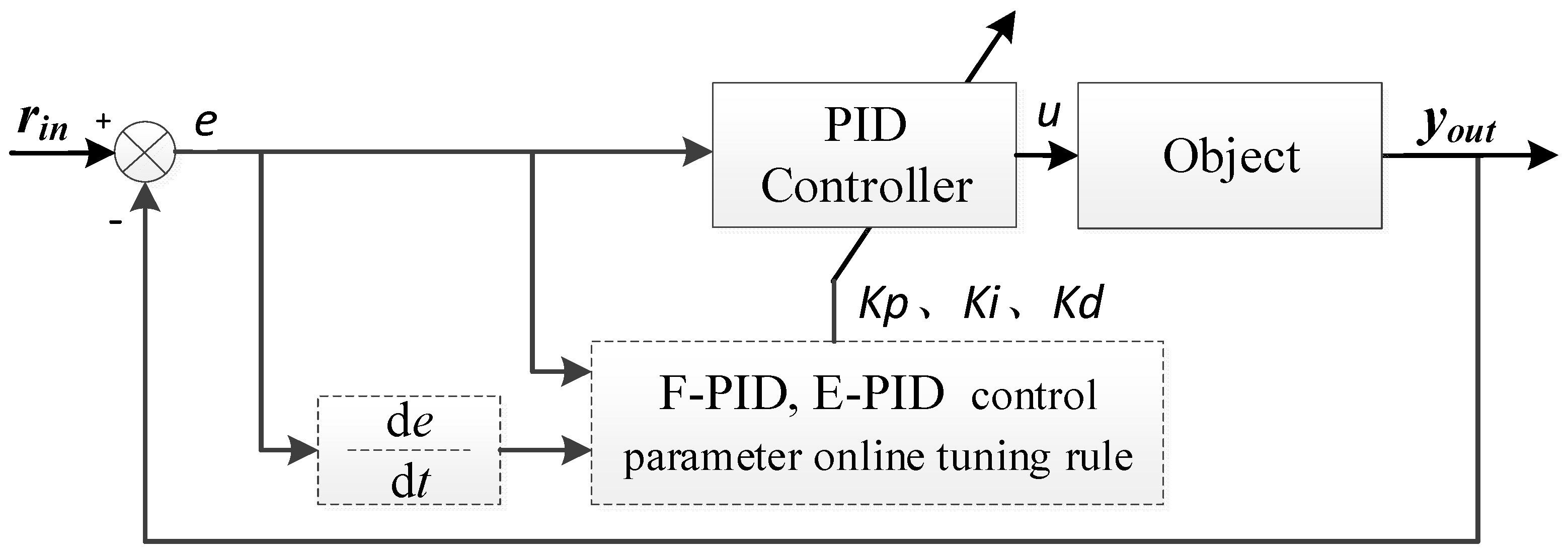
First of all, the structure of a classical PID control system is shown in Figure 1. At time t, according to system input and output, system error (e and de/dt) can be calculated. According to e and d e / d t , the PID controller will calculate the amount of control u as the input of the controlled object. Control parameters K p , K i , K d have been set to a fixed value before the system is started. Under the influence of u, the output of the controlled object will be updated, which is the system output at time t + 1. The above process is an adjustment cycle.
Definition 1.
Adjustment cycle (AC). 1 AC is only one control process at one fixed simulation time (e.g., t = 3 ). In each AC, system errors e r r o r ( t ) and d e r r o r ( t ) , updated parameters k p ( t ) , k i ( t ) , k d ( t ) , control amount u(t), and updated system output y o u t ( k ) will be updated once.
Definition 2.
Simulation cycle (SC). 1 SC is an independent control process, which is from the start time of the control process at time t = 1 to the end time (e.g., max simulation time m a x _ t = 3000 ) of the control process (before the end time, the system will usually reach steady-state and remain stable). 1 SC is composed of n AC.
The model of a classical PID controller can be defined as Equation (1):
u ( t ) = K p · ( e ( t ) + 1 K i e ( t ) d t + K d d e ( t ) d t )
The model of an AI-CC controller can be defined as Equation (2):
u ( t ) = K p ( t ) · ( e ( t ) + 1 K i ( t ) e ( t ) d t + K d ( t ) d e ( t ) d t )
K p ( t ) , K i ( t ) ,   a n d   K d ( t ) are the control parameters that will be online-tuned in each adjustment cycle by the AI-CC methods proposed in this study.
In each adjustment cycle at time t , the output of the controller is u ( t ) = u ( t 1 ) + Δ u ( t ) . The updated u ( t ) is calculated according to the incremental PID method, which is expressed as Equation (3):
Δ u ( t ) = k p ( t ) ( e ( t ) e ( t 1 ) ) + k i ( t ) e ( t ) + k d ( t ) ( e ( t ) 2 e ( t 1 ) + e ( t 2 ) )
The output of the control system is y ( t ) , which can be calculated according to the method of digital PID for discrete systems. Firstly, the transfer function of the controlled object is discretized to a ( i ) and b ( j ) . Secondly, y ( t ) is calculated as Equation (4).
y ( t ) = a ( 2 ) y ( t 1 ) a ( 3 ) y ( t 2 ) a ( 4 ) y ( t 3 ) + b ( 2 ) u ( t 1 ) + b ( 3 ) u ( t 2 ) + b ( 4 ) u ( t 3 )
The pseudocode for the PID control method can be presented as Algorithm 1:
Algorithm 1 PID (proportion integration differentiation) control method
  • Begin
  •           Initialize PID control system;
  •           While ( t m a x _ t )  do:
  •                     Simulation time updated: t = t + 1 ;
  •                     System input r i n ( t )  is updated;
  •                     Calculate Δu(t) and u(t) according to Equation (3);
  •                     Calculate yout(t) according to Equation (4);
  •                     Calculate e ( t ) = y ( t ) r i n ( t ) ;
  •           End while
  • End

2.2. E-PID and F-PID Models (Existing Methods)

E-PID and F-PID are typical systems for AI-CC parameter online-tuning with the intelligence of expert and fuzzy rules. The structure of the E-PID and F-PID control systems are shown in Figure 2.
Compared with classical PID, the features and differences of E-PID and F-PID are as follows: According to the control parameter online-tuning rule, the control parameters K p , K i , K d of the PID controller will be updated in each adjustment cycle.
Definition of F-PID: If the control parameter online-tuning rule is the fuzzy calculation algorithm, the AI-CC system is called a fuzzy-reasoning-based method for parameter online tuning, which can be abbreviated as F-PID.
The online-tuned control parameters of F-PID are calculated as Equations (5)–(7), where R K p F , R K i F , R K d F are outputs of fuzzy computing.
K p ( t ) = R K p F ( e ( t ) , e c ( t ) )
K i ( t ) = R K p F ( e ( t ) , e c ( t ) )
K d ( t ) = R K p F ( e ( t ) , e c ( t ) )
Definition of E-PID: If the control parameter online-tuning rule is the expert system algorithm, the AI-CC system is called an expert-rule-based parameter online-tuning control method, which can be abbreviated as E-PID.
The principle of the E-PID model is similar to that of the F-PID model: the control parameters of E-PID are calculated as Equations (8)–(10), –which means the parameters of E-PID can be obtained directly from the E-PID rule table.
K p ( t ) = R K p E ( e ( t ) , e c ( t ) )
K i ( t ) = R K p E ( e ( t ) , e c ( t ) )
K d ( t ) = R K p E ( e ( t ) , e c ( t ) )
The pseudocode of E-PID and F-PID control methods can be presented as Algorithm 2:
Algorithm 2 E-PID (Expert system based PID) and F-PID (Fuzzy calculation based PID) control methods
  • Begin
  •         Initialize X-PID control system model;
  •         Input Expert Rules’ Table (or Fuzzy Rules);
  •         While ( t m a x _ t )  do:
  •               Simulation time updated: t = t + 1 ;
  •               System input r i n ( t )  is updated;
  •               Calculate error(t) and derror(t);
  •               Query R K p E , R K i E , R K d E or R K p F , R K i F , R K d F according to Epxert rule table (or Fuzzy rules);
  •               Kp(t), Ki(t), Kd(t) are adjusted according to Equations (5)–(7) or Equations (8)–(10);
  •               Calculate Δu(t) and u(t) according to Equation (3);
  •               Calculate yout(t) according to Equation (4);
  •         End while
  • End

2.3. Application of E-PID and F-PID (Existing Application)

E-PID and F-PID are widely used in many applications because of its simple structure. E-PID was applied to a servo system by F. Kang, and the experimental results showed that E-PID could obtain an excellent control effect [23]. F-PID was applied to robot arm motion control by Ji, Y.L. [24]. F-PID has also been used to realize depth control for ROV (Remote Operated Vehicle) in a nuclear power plant.
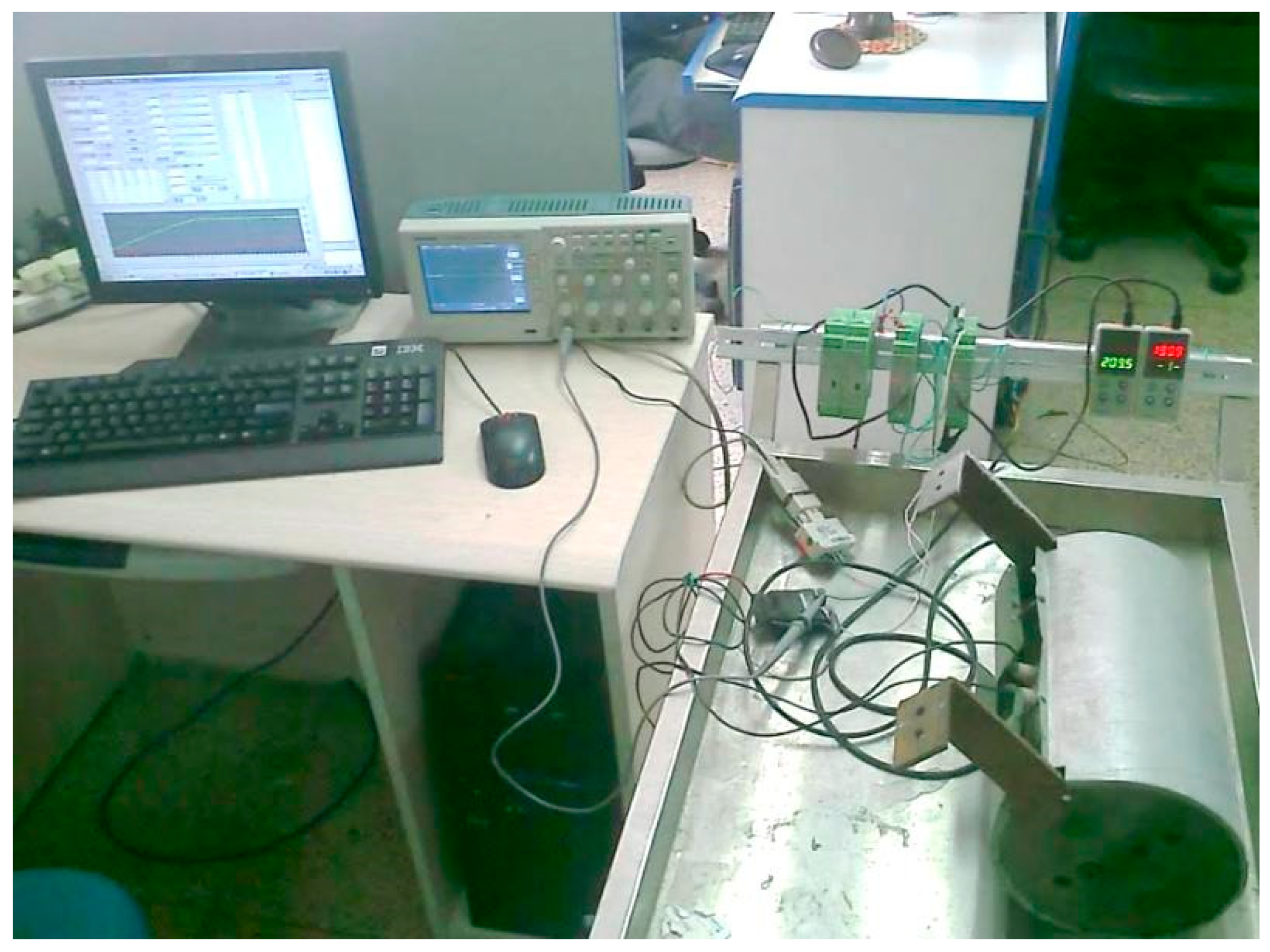
As to an existing practical application of the E-PID and F-PID system, a heating control system of an oil production process is shown in Figure 3. (1) The three small green devices in the middle-right of Figure 3. are PID controllers. The small white devices on the right side are display and setting devices, which are connected to the sensors in the heating object and the PID controller. The computer is connected to the PID controller by an RS-485 data cable, which is designed to read the temperature of the controlled heating equipment and adjust the control parameters K p , K i , K d in each adjustment cycle. The cylindrical device on the right is the heating device; the input of this heating device is connected to the output of the PID controller to get the power voltage, which is monitored by the oscilloscope in the middle-left Figure 3.

3. EA-PID and FA-PID Models (Improved Methods)

The problems of E-PID and F-PID are as follows: The online-tuned parameters of E-PID and F-PID are set as fixed absolute values according to the expert rule table in E-PID and the fuzzy calculation formula in F-PID. Although K p , K i , K d can be updated in each adjustment cycle, the intelligence and performance features of E-PID and F-PID methods are limited.
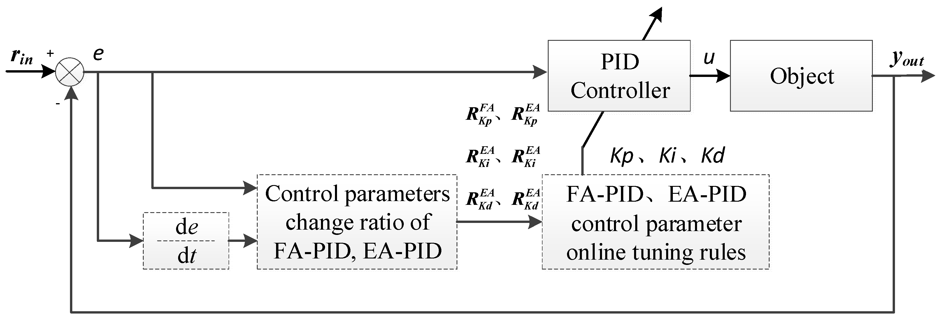
In order to solve the above problems, EA-PID and FA-PID methods are proposed in this study. In EA-PID and FA-PID methods, the parameters are tuned by the change ratio instead of the absolute values in each adjustment cycle.
Definition 3.
EA-PID: In this study, EA-PID is an improved intelligent PID control method based on E-PID. Compared with E-PID, the ERT of E-PID is replaced by Change Ratio Table (CRT) in EA-PID. In EA-PID, the adjusted 𝐾𝑝(𝑡),𝐾𝑖(𝑡), and 𝐾𝑑(𝑡) at time 𝑡 are the multiplied result of change ratio 𝑅𝐾𝑝(𝑡), 𝑅𝐾𝑖(𝑡), and 𝑅𝐾𝑑(𝑡) at time 𝑡 and 𝐾𝑝(𝑡 − 1),𝐾𝑖(𝑡 − 1),𝐾𝑑(𝑡 − 1) at time 𝑡 − 1, respectively.
Definition 4.
FA-PID: In this study, FA-PID is an improved intelligent PID control method based on F-PID. In FA-PID method, control parameters at time 𝑡 are adjusted according to the result of multiplying change ratio and parameters at time 𝑡 – 1, while the control parameters at time 𝑡 are adjusted according to the result of fuzzy calculation.
The structure of the EA-PID and FA-PID control systems are shown in Figure 4.
Definition 5.
Change ratio: The change ratio R ( t ) is a proportion between the control parameters at time t and t 1 . The new control parameter is calculated as K ( t ) = K ( t 1 ) · R ( t ) .

3.1. FA-PID Model

3.1.1. Improve F-PID to FA-PID

In FA-PID, R K p F A ( e ( k ) , e c ( k ) ) is the change ratio for K p at time k , which is the output of fuzzy calculation. The online-tuned control parameters of FA-PID at time t are calculated as Equations (11)–(13):
K p ( t ) = R K p F A ( e ( t ) , e c ( t ) ) · K p ( t 1 )
K i ( t ) = R K i F A ( e ( t ) , e c ( t ) ) · K i ( t 1 )
K d ( t ) = R K d F A ( e ( t ) , e c ( t ) ) · K d ( t 1 )

3.1.2. Design of Fuzzy Controller

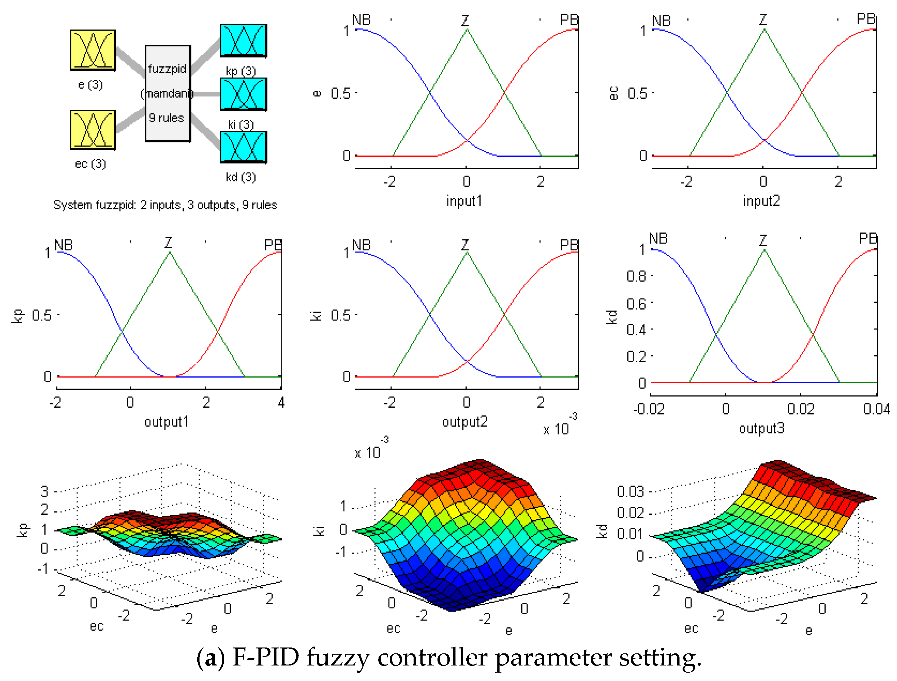
The fuzzy controller of F-PID and FA-PID is designed and shown in Figure 5. F-PID is designed as Figure 5a, and FA-PID is designed as Figure 5b.
A centroid is adopted as the method of defuzzification, which returns the center of gravity of the fuzzy set along the x-axis. The formula of the centroid is expressed as Equation (14):
x C e n t r o i d = i = 1 n μ ( x i ) . x i i = 1 n μ ( x i )

3.2. EA-PID Model

3.2.1. Improve E-PID to EA-PID:

Change ratios for updating K p , K i , K d of EA-PID, given by expert experience, can be designed, as in Table 1. For example, R h h is one case of a change value when e ( t ) is very large and e c ( t ) is very large. E h i g n and E l o w are the boundary values.
R K d E A ( e ( t ) , e c ( t ) ) is the change ratio at time t. The control parameters of EA-PID are calculated as Equations (15)–(17):
K p ( t ) = R K p E A ( e ( t ) , e c ( t ) ) · K p ( t 1 )
K i ( t ) = R K i E A ( e ( t ) , e c ( t ) ) · K i ( t 1 )
K d ( t ) = R K d E A ( e ( t ) , e c ( t ) ) · K d ( t 1 )

3.2.2. Design of an Expert Rule Table

The design of the rule table of the EA-PID algorithm is shown in Table 2, Table 3 and Table 4, which is similar to the rule table of the E-PID algorithm.

3.3. Implementation of EA-PID and FA-PID

In E-PID and F-PID methods, the values of the updated K p ( t ) , K i ( t ) , K d ( t ) are queried directly according to Equations (5)–(7) and Equations (8)–(10), respectively.
In EA-PID and FA-PID methods, the change ratios R p ( t ) , R i ( t ) , R d ( t ) are queried first. Then, the value of the updated K p ( t ) , K i ( t ) , K d ( t ) are calculated as K p ( t 1 ) · R p ( t ) , K i ( t 1 ) · R i ( t ) , K d ( t 1 ) · R d ( t ) . Details are shown in Equations (11)–(13) and Equations (15)–(17) for each method, respectively.
The control system and AI-CC algorithms of EA-PID or FA-PID can be designed as Algorithm 3:
Algorithm 3 EA-PID and FA-PID (which are defined in Definition 3 to 4) control methods
  • Begin
  •         Initialize XA-PID control system model;
  •         Input Expert rule table or Fuzzy rules;
  •         While ( t m a x _ t )  do:
  •               Simulation time updated: t = t + 1 ;
  •               System input r i n ( t )  is updated;
  •               Calculate error(t) and derror(t);
  •               Query R K p E A , R K i E A , R K d E A or R K p F A , R K i F A , R K d F A according to Expert rule table (or Fuzzy Rules);
  •               Adjustd parameters (online tuning) like K p ( t ) = K p ( t 1 ) R K p E ( t )  are calculated according to Equations (11)–(13) or Equations (15)–(17);
  •               Calculate Δu(t) and u(t) according to Equation (3);
  •               Calculate yout(t) according to Equation (4);
  •         End while
  • End

3.4. Comparison of E-PID, F-PID, EA-PID, and FA-PID

All the comparative results of F-PID, E-PID, FA-PID, and EA-PID methods are listed in Table 5.

4. WNN-PID Model (Improved Method)

4.1. WNN-PID Model

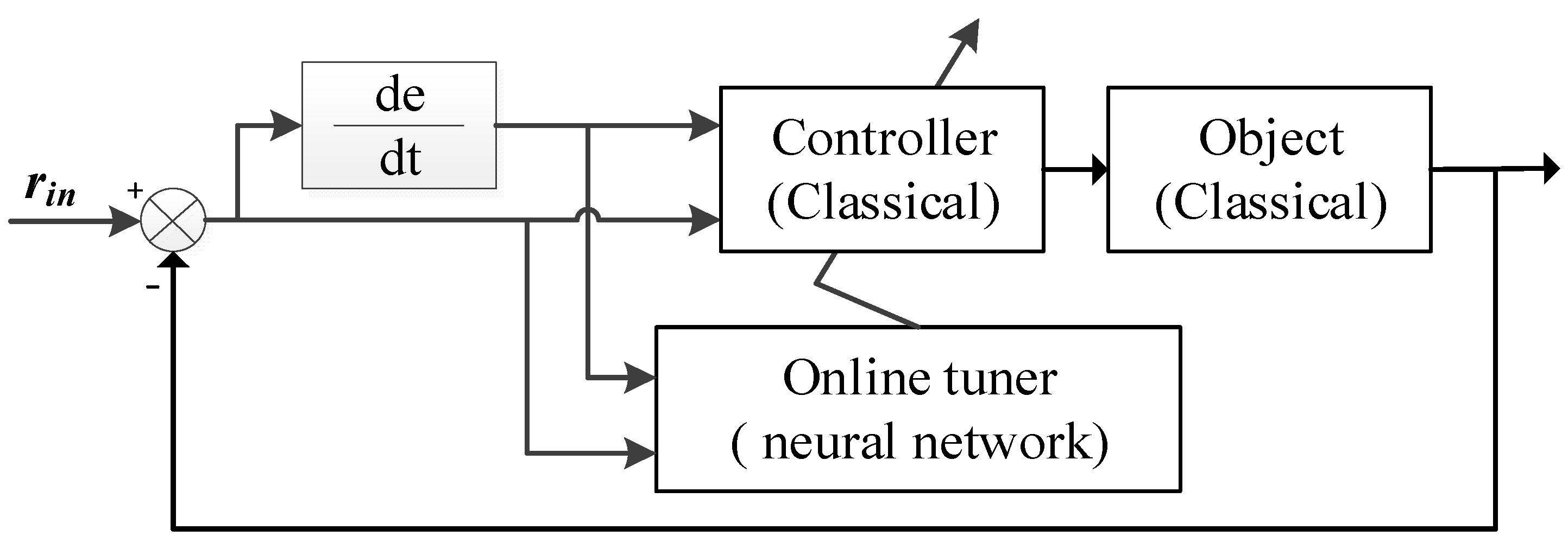
The structure of the neural-network-based AI-CC system is shown in Figure 6. The difference between Figure 2 (E-PID and F-PID), Figure 4 (EA-PID and FA-PID), and Figure 6 is, in Figure 6, the parameters of the classic controller is tuned online by a neural network (online tuner).
BPNN-PID, RBFNN-PID, and WNN-PID are neural-network-based AI-CC methods. F-PID, FA-PID, E-PID, and EA-PID are reasoning-based AI-CC methods.
The algorithms of NN-PID (BPNN-PID, RBFNN-PID, or the proposed WNN-PID) can be designed as Algorithm 4:
Algorithm 4 NN-PID(neural network based proportion integration differentiation) control method
  • Begin
  •           Initialize NN-PID control system model;
  •           Initialize NN weights Wmn(t) and offsets bl(t);
  •           While ( t m a x _ t )  do:
  •                    Simulation time updated: t = t + 1 ;
  •                    System input r i n ( t )  is updated;
  •                    Calculate error(t) and derror(t);
  •                    Wmn(t) and bl(t) are trained and updated according to Equations (28)–(37);
  •                    Kp(t), Ki(t), Kd(t) are adjusted according to NN forward calculation as Equations (20)–(27);
  •                    Calculate Δu(t) and u(t) according to Equation (3);
  •                    Calculate yout(t) according to Equation (4);
  •           End while
  • End
According to existing BPNN-PID and RBFNN-PID, the WNN-PID method is proposed as an online tuner in this study. Moreover, BPNN-PID and RBFNN-PID are selected as comparative algorithms to verify the advantages of the WNN-PID method.
The key to the NN-based parameter online-tuning algorithm is that finding the minimum mean of square error of system outputs is the training target of the neural network tuner. The target function can be expressed as Equation (18).
min E ( t ) = 1 2 ( r i n ( t ) y o u t ( t ) ) 2
An alternative target function can be expressed as Equation (19). According to the simulation results, the different target functions will affect the results in numerical differences, but this does not affect the results and order of comparative simulations. Hence, both of the target functions can be adopted; all the NNs should apply the same target functions. In this study, the mean square error of Equation (18) is adopted as the target function for comparison.
min E ( t ) = | r i n ( t ) y o u t ( t ) |
Control parameters K p ( t ) , K i ( t ) , K d ( t ) are the result of the forward propagation of NNs according to Equations (20)–(27).
{ net 1 ( 1 ) ( t ) = r in ( t ) net 2 ( 1 ) ( t ) = y out ( t 1 ) net 3 ( 1 ) ( t ) = error ( t )
{ K p ( t ) = O 1 ( 3 ) ( t ) K i ( t ) = O 2 ( 3 ) ( t ) K d ( t ) = O 3 ( 3 ) ( t )
O j ( 2 ) ( t ) = Ψ ab ( n e t j ( 2 ) ( t ) b j ( t ) a j ( t ) )
n e t k ( 3 ) ( t ) = j = 1 Q w j k ( 3 ) ( t ) · O j ( 2 ) ( t )
O k ( 3 ) ( t ) = g ( n e t k ( 3 ) ( t ) )
g ( x ) = = e x e x + e x
Ψ ab ( t ) = cos ( 1.75 t ) · e t 2 2
Ψ a , b ( t ) = 1.75 · sin ( 1.75 t ) · e t 2 2 t · cos ( 1.75 t ) · e t 2 2
Ψ ab ( t ) is the scale transformation function of the hidden layers of WNN. The selection of Ψ ab ( t ) must satisfy the framework condition. O j ( 2 ) ( t ) is the output of the hidden layer, O k ( 3 ) ( t ) is the output of the output layer.

4.2. Online Tuning Algorithm of WNN-PID

Common training algorithms are the gradient descent method, Newton’s method, the quasi-Newton method, and the conjugate gradient method. Among the above, the gradient descent method is the earliest, simplest, and most commonly used method. Hence, the gradient descent method is adopted as the training algorithm for BPNN-PID, RBFNN-PID, and WNN-PID methods.
The gradient descent method in the training algorithm can be designed as follows:   w j k ( 3 ) and w i j ( 2 ) are neural network weights. Δ a j ( t ) and Δ b j ( t ) are the scale parameters of the activation function in the hidden layer.   w j k ( 3 ) , w i j ( 2 ) , Δ a j ( t ) and Δ b j ( t ) are changed to Equations (28)–(31).
Δ w j k ( 3 ) ( t ) = α Δ w j k ( 3 ) ( t 1 ) η E ( t ) w j k ( 3 ) ( t )
Δ w i j ( 2 ) ( t ) = α Δ w i j ( 2 ) ( t 1 ) η E ( t ) w i j ( 2 ) ( t )
Δ a j ( t ) = α Δ a j ( t 1 ) η E ( t ) a j ( t )
Δ b j ( t ) = α Δ b j ( t 1 ) η E ( t ) b j ( t )
Details of the above differentiation formulas are given in Equations (32)–(37):
E ( t ) w j k ( 3 ) ( t ) = e r r o r ( t ) sgn ( y ( t ) Δ u ( t ) ) Δ u ( t ) o k ( 3 ) ( t ) g ( n e t k ( 3 ) ( t ) ) o j ( 2 ) ( t )
E ( t ) w i j ( 2 ) ( t ) = k = 1 L δ k ( 3 ) ( t ) w j k ( 3 ) ( t ) ψ a , b ( n e t j ( 2 ) ( t ) b j ( t ) a j ( t ) ) 1 a j ( t ) o i ( 1 ) ( t )
E ( t ) a j ( t ) = k = 1 L δ k ( 3 ) ( t ) w j k ( 3 ) ( t ) ψ a , b ( n e t j ( 2 ) ( t 10 . ) b j ( t ) a j ( t ) ) ( n e t j ( 2 ) ( t ) b j ( t ) a j 2 ( t ) )
E ( t ) a j ( t ) = k = 1 L δ k ( 3 ) ( t ) w j k ( 3 ) ( t ) ψ a , b ( n e t j ( 2 ) ( t ) b j ( t ) a j ( t ) ) ( n e t j ( 2 ) ( t ) b j ( t ) a j 2 ( t ) )
δ k ( 3 ) ( t ) = e r r o r ( t ) sgn ( y ( t ) u ( t ) ) u ( t ) o k ( 3 ) ( t ) g ( n e t k ( 3 ) ( t ) )
g ( x ) = e x e x + e x , g ( x ) = 2 ( e x + e x ) 2

5. Simulation

5.1. Design and Result Analysis of the Simulations

5.1.1. Simulation of EA-PID and FA-PID

Designs of the EA-PID and FA-PID simulations are based on E-PID and F-PID; designs of E-PID and F-PID simulations are based on the digital incremental PID discussed before. The change value R K p E ( t ) is replaced by the change ratio R K p F A ( t ) in the EA-PID method, and the change value R K p F ( t ) is replaced by the change ratio R K p F A ( t ) in the EA-PID method.
Simulation parameters for the above 4 methods (E-PID, F-PID, EA-PID, and FA-PID) should be set similarly.
Basic configuration:
(1) In each AC, K p ( k ) , K i ( k ) , K d ( k ) parameters are tuned once. (2) The incremental digital PID algorithm is adopted as the controller model. (3) Second-order with delay is used as the controlled object model, which can be expressed as s y s ( s ) = 200 s 2 + 30 s + 1 · e s . (4) Sampling period (interval between each AC) is set as t s = 1 , which means that one program loop corresponds to one sample period. (5) The initial value of control parameters are set as K p ( 0 ) = 1 , k i ( 0 ) = 0.1 , K d ( 0 ) = 0 , which are verified to keep the system running steadily. (6) System input is set as r i n ( k ) 1 for step response.
  • Anti-interference Configuration 1 for the saturation test.
(1) The max simulation time (max number of AC) is set as max _ k = 8000 in order to ensure that the system can be stabilized, and the interference can maximize the effect. (2) The start time of interference is at d _ k = 2000 (after the output reaches steady-state). (3) The interference duration is set as I   _ k = 6000 in order to test the features of saturation and convergence of the system output. (4) Interference intensity (amplitude or strength of disturbance) is set as d s t _   u ( k ) = 0.5 , which is added to the output of the PID controller. In summary: from simulation time 2000 to 6000, the control amount (output of PID controller) is changed to u ( k ) + d s t _   u ( k ) .
Simulation 1 is a saturation test that is based on basic configuration and Anti-interference Configuration 1. The results of the above 4 methods (E-PID, F-PID, EA-PID, and FA-PID) are shown in Figure 7.
2.
Anti-interference Configuration 2 for the unsaturation experiment.
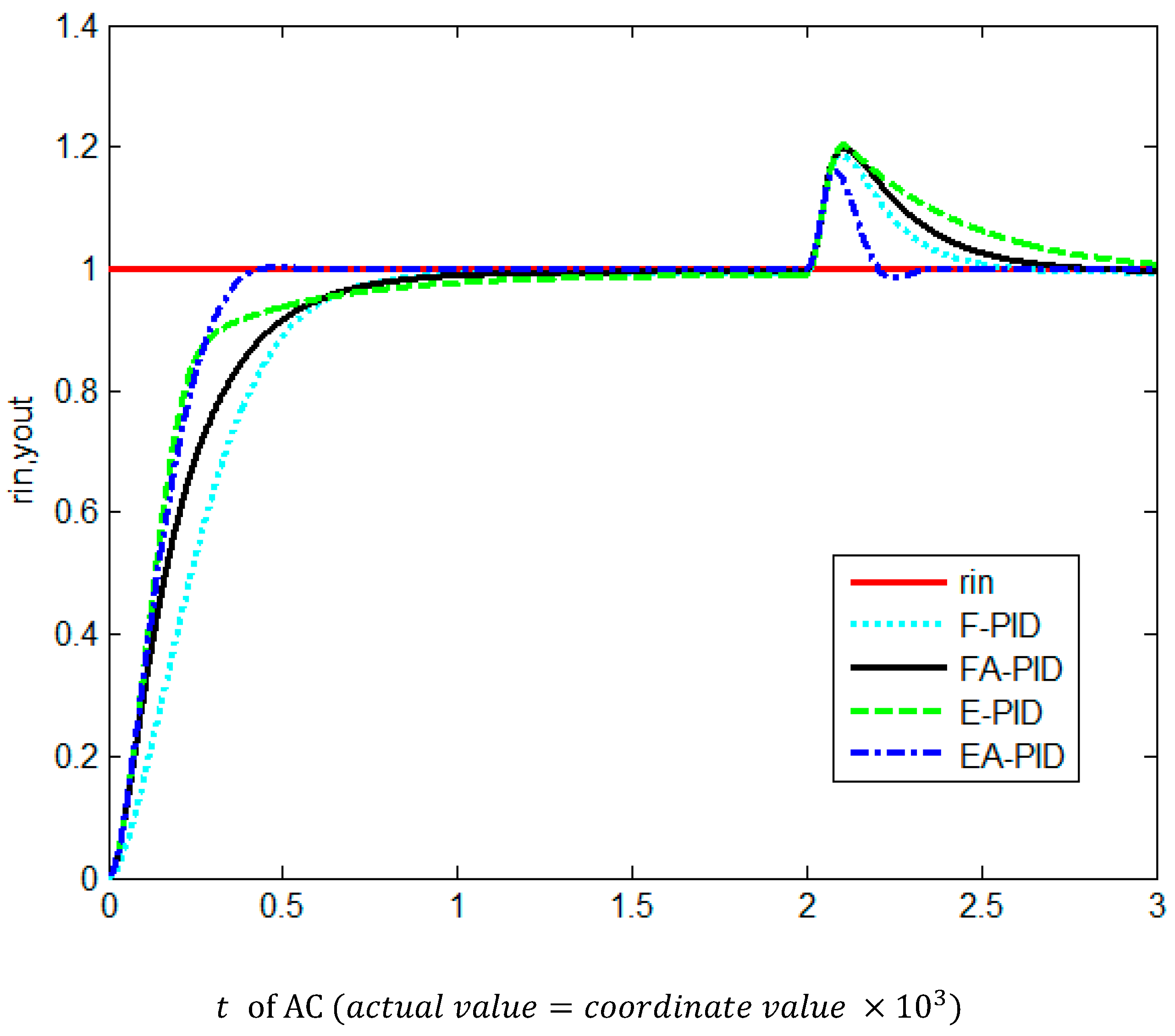
(1) The max simulation time is set as max _ k = 3000 . (2) The start time of interference is at d _ k = 2000 . (3) The interference duration is set as I   _ k = 10 . (4) Interference intensity is set as d s t _   u ( k ) = 0.5 , which is added to the output of the PID controller. In summary: from simulation time 2000 to 2010, the control amount (output of PID controller) is changed to u ( k ) + d s t _   u ( k ) .
Simulation 2 is an unsaturation experiment that is based on basic configuration and Anti-interference Configuration 2. The results of the above 4 methods (E-PID, F-PID, EA-PID, and FA-PID) are shown in Figure 8.
The above simulation results show that
  • The control speed of EA-PID is the best: The rising curve (especially when AC is at 0 to 500) in Figure 7 and Figure 8 shows that E-PID and EA-PID are faster than F-PID and FA-PID. EA-PID has the fastest speed to reach a steady state (settling time of EA-PID is the smallest value). The speed of FA-PID is faster than F-PID (shorter rise time and steady time). Only EA-PID has overshot.
  • The steady-state error of EA-PID is the smallest. The steady-state error of FA-PID is smaller than F-PID, when AC is at 0 to 1500 in Figure 7 and Figure 8.
  • EA-PID has the best ability of anti-interference, FA-PID has the second-best ability of anti-interference, E-PID is saturated under the influence of continuous interference, and F-PID is the worst performer (unstable, does not converge) when AC is at 2000 to 10,000 in Figure 7.
  • The anti-interference ability and recovery speed of EA-PID are the best. The recovery curve (when AC is at 2010 to 2300) in Figure 8 shows that the recovery time of EA-PID is the shortest. The maximum values of system output in Simulation 1 (Figure 7) prove that the control system is unsaturation in Simulation 2 (Figure 8) because the amplitude of system output in Simulation 1 (with longer time of interference) is larger than in Simulation 2.
In conclusion, most control performances of EA-PID are the best. Most control performances of FA-PID are better than F-PID. More simulation details of Figure 8 are listed in Table 6.
In Table 6, data in columns of rise time T r and settling time T s show the features of control speed. Data in the overshoot column show the overadjustment ability. Data in the steady-state error column show the tracking ability of the control system. The best values are in bold and underlined in Table 6.

5.1.2. Simulation of BPNN-PID, RBFNN-PID, and WNN-PID

Simulations of BPNN-PID, RBFNN-PID, and WNN-PID are designed together with the same parameters and methods in order to compare their performance.
Firstly, the same designs of all the above three NN-PID systems are as follows:
(1) e and e c are inputs of BPNN, RBFNN, and WNN [25]. (2) The hidden layers of BPNN, RBFNN, and WNN have 20 neurons. (3) The learning efficiency of BPNN, RBFNN, and WNN is set to η = 0.2 , and the coefficient of inertia of BPNN, RBFNN, and WNN is set to α = 0.3 . (4) The sample size of training is the same as the size of the simulation time: max _ k = 3000 . (5) Three groups of repeated simulations are designed to get the statistic features of BPNN-PID, RBFNN-PID, and WNN-PID; this is similar to the methods of cross-validation [26,27]. In each simulation group, the simulations are repeated 30 times. (6) The null hypothesis is that the difference in simulation results, such as rising time, settling time, and steady-state error, is more than 10%. The alternative hypothesis is that the difference in simulation results is less than 10%.
Secondly, the same configurations of all the above simulations are as follows:
(1) In each AC (see Definition 1), parameters should be tuned once. (2) The incremental digital PID algorithm is adopted as the controller model. (3) Second-order with delay is used as the controlled object model, which can be expressed as s y s ( s ) = 200 s 2 + 30 s + 1 · e τ s . (4) Sampling period (AC interval) is set as t s = 1 , which means that one program loop corresponds to one sample period. (5) Max simulation time is set as max _ k = 3000 , which is designed to be large enough to ensure that the system can be stabilized. (6) System input is set as r i n ( k ) 1 for step response. (7) In order to make the experimental results more stable and convincing, each SC will be repeated 10 times.
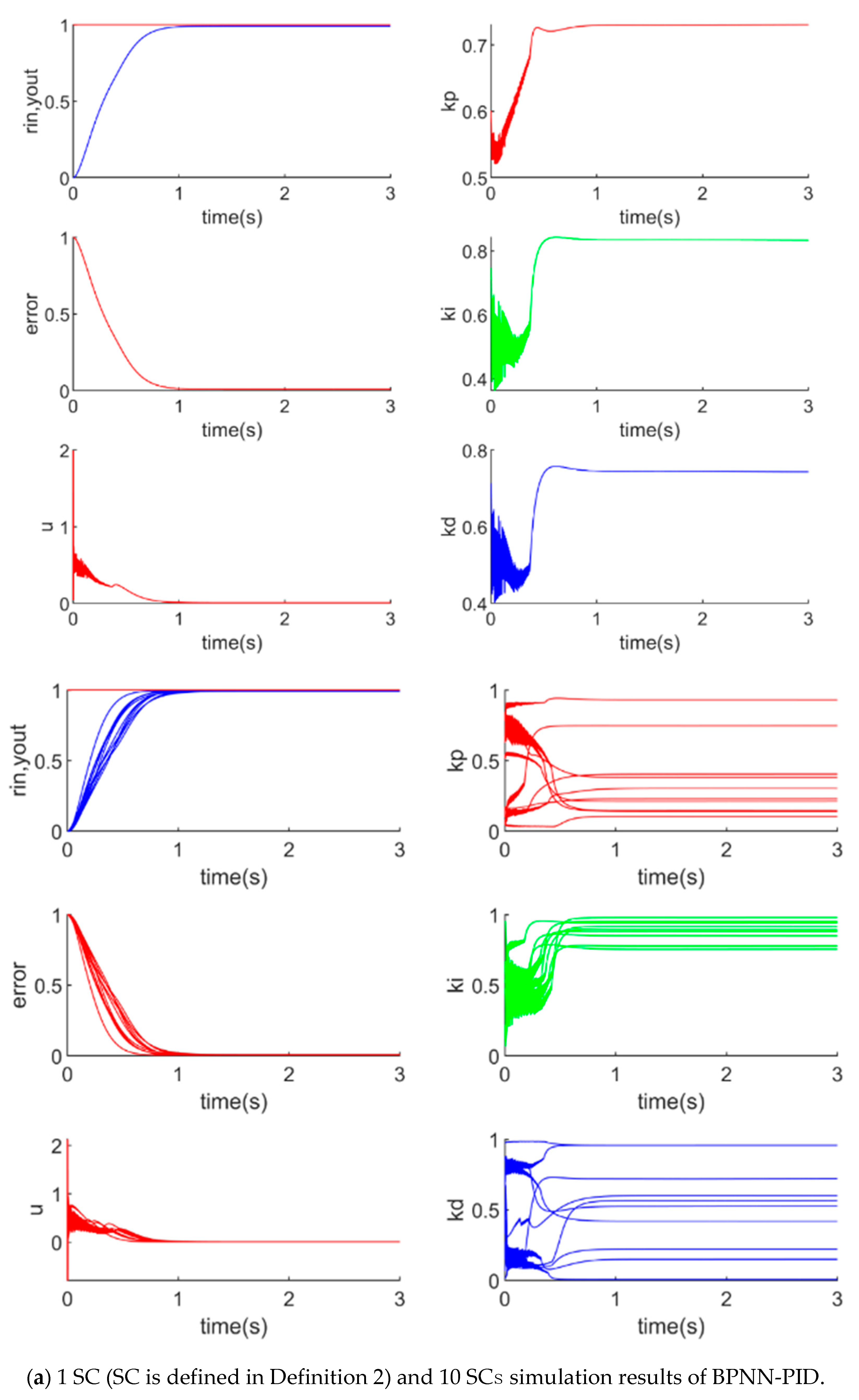
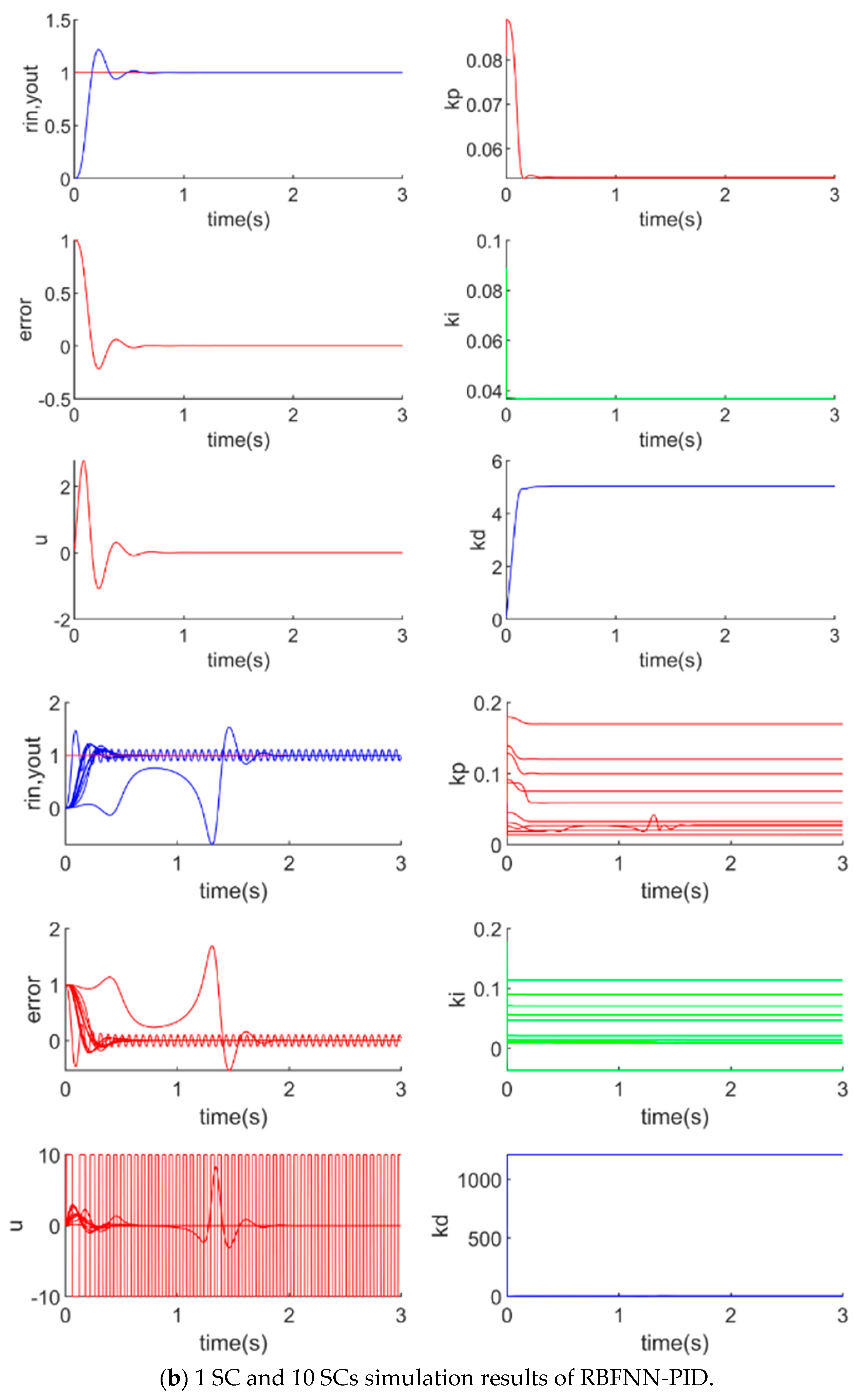
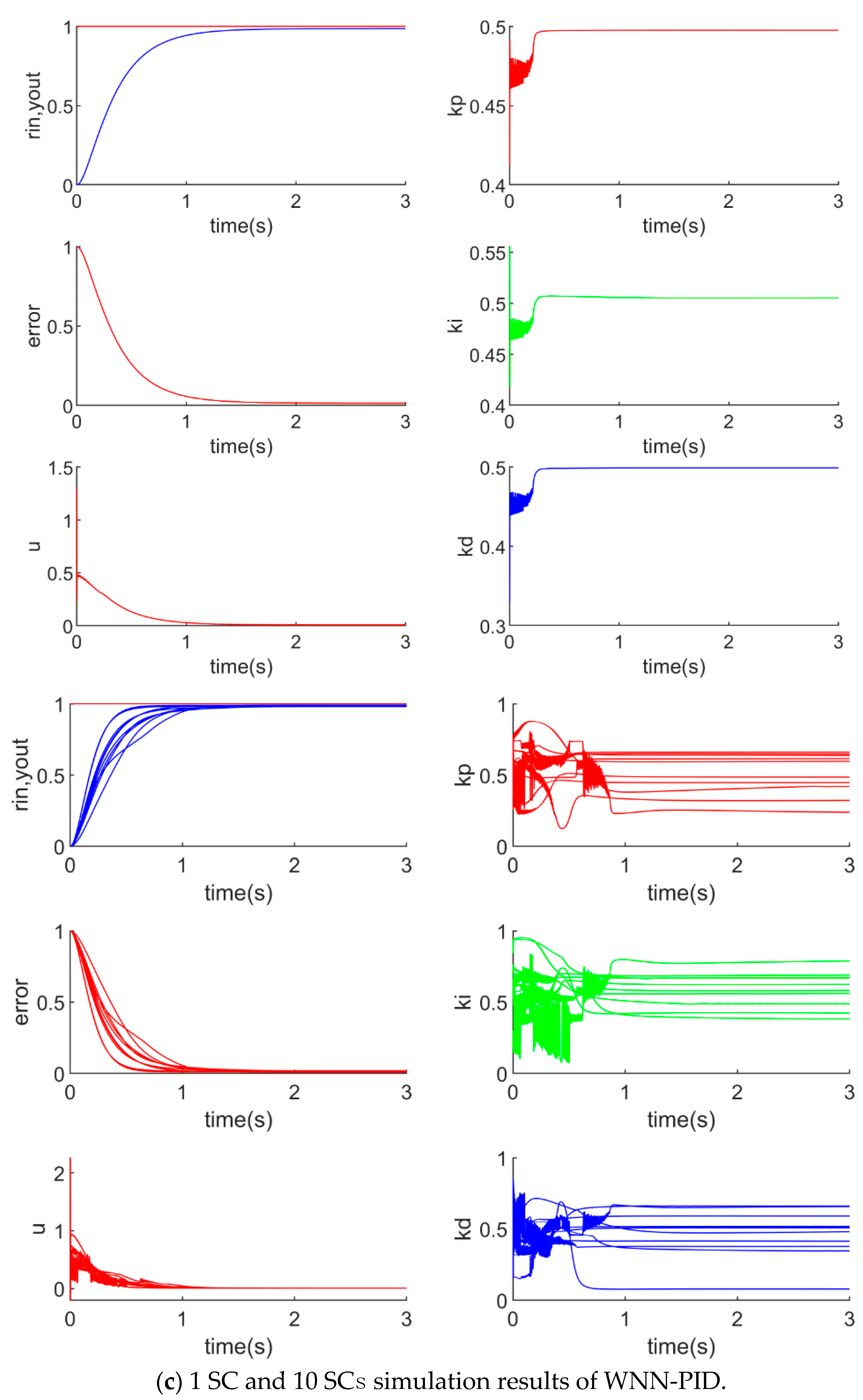
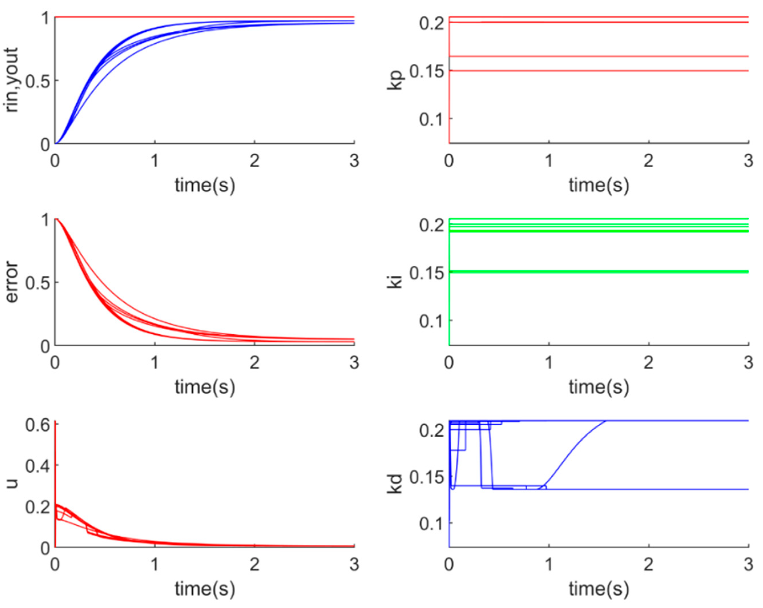
The simulation results of the 10 repeated SC of BPNN-PID, RBFNN-PID, and WNN-PID are drawn in Figure 9. Curve of system input, output, error, output of controller, and parameters of K p , K i , K d simulation time are plotted.
In Figure 9, each SC is different from the others because the results of the initialization of the neural networks are different. As a result of different initialized weights and bias, the output of K p , K i , K d , u , y o u t , e r r o r are different in different SCs.
The above results show that (1) all the NN-PID methods are verified as feasible: the output curves can approach system input and keep stable; (2) stability of WNN-PID and BPNN-PID are better than RBFNN-PID: unstable cases only happened in RBFNN-PID simulations. The unstable problem will be solved by stability guarantee methods in the following section of this study.
The results of repeated 30 SCs, (each SC has 3000 ACs, m a x _ k = 3000 ), of BPNN-PID, RBFNN-PID, and WNN-PID are shown in Table 7.
Table 7 shows that (1) the control speed of WNN-PID is faster than BPNN-PID according to rise time ( T r ) and time of settling time ( T s ). Some of the control speeds of RBFNN-PID are faster than WNN-PID and BPNN-PID, but some of the control speeds of RBFNN-PID are unstable. (2) The steady-state error of BPNN-PID is the smallest among all NN-PID methods.
Three additional groups of statistical tests are implemented. In each group of statistical tests, simulations are repeated 30 times. The average results of the above three groups of simulations are shown in Table 8, which shows that the above conclusions have the same statistical characteristics. The difference in simulation results, such as rising time, settling time, and steady-state error, is smaller than 10%

5.2. Comparison and Analysis of all Simulations

5.2.1. Analysis of Dynamic and Steady-State

The performance features of the above seven AI-CC methods (F-PID, FA-PID, E-PID, EA-PID BPNNPID, RBFNN-PID, and WNN-PID) are summarized. Data in columns of rising time and settling time show the features of control speed. Data in columns of steady-state error show the capability with output-tracking input of the system. In Table 9, EA-PID is focused on a comparison with all X-PID because all the features of EA-PID are the best. FA-PID is focused on a comparison with F-PID because FA-PID is improved in comparison to F-PID. WNN-PID is focused on a comparison with BPNN-PID because WNN-PID is improved in comparison to BPNN-PID. RBFNN-PID is not compared to BPNN-PID and WNN-PID because RBFNN-PID is not stable and a performance discussion of an unstable method is worthless.
Comparative results in Table 9 show that
  • Most features of EA-PID are the best because all the EA-PID result data (line 2) in Table 9 have the smallest values. Therefore, the improvement of EA-PID is successful.
  • FA-PID is better than F-PID because all the FA-PID result data (line 4) in Table 9 are smaller values than F-PID (line 3). Therefore, an improvement from F-PID to FA-PID is successful.
  • Most speed features of WNN-PID (line 7) are better than BPNN-PID (line 5), but the steady-state error feature of WNN-PID is not. RBFNN-PID (line 6) did not participate in the comparison because it is unstable.

5.2.2. Analysis of Anti-Interference

An anti-interference analysis is as important as a stability analysis. Robust simulations are designed as follows:
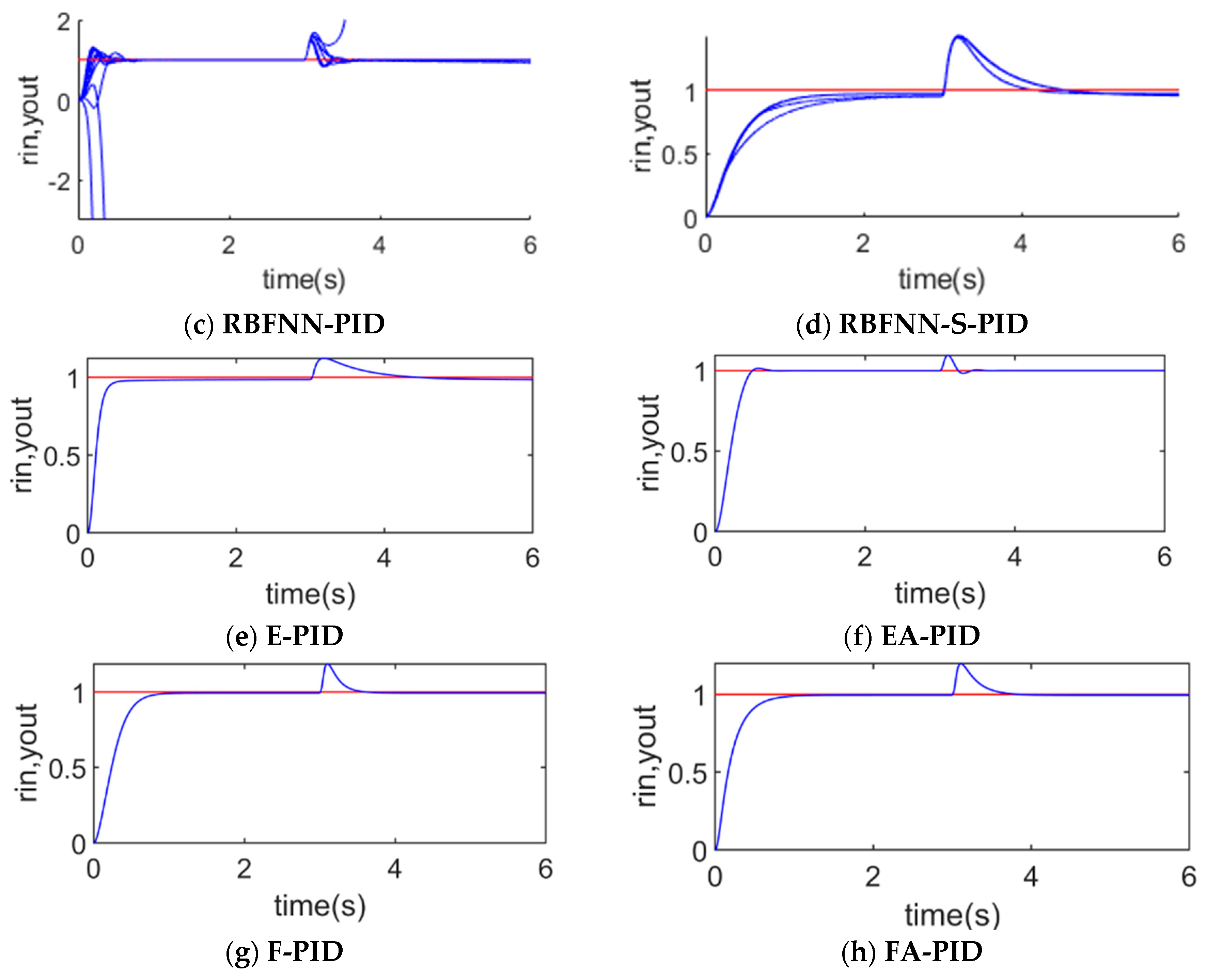
  • Start time of interference (IST) is set after the adjustment time T s (when the system output reaches 90% of system input). For most AI-CC methods, IST is set to 2000. In RBFNN-S-PID method, IST is set to 3000 because T s of RBFNN-S-PID >2000. Duration time of interference (IDT) is set to 100 ACs.
  • The maximum simulation time is set to be long enough to ensure that the recovery process from interference can be clearly observed.
  • All the other simulation parameters are set to be the same value as in the previous sections.
The simulation results plotted in Figure 10 show that most AI-CC systems have an acceptable anti-interference ability except RBFNN-PID. Some curves in the RBFNN-PID plots are not convergent (unable to reach steady-state after receiving interference). However, this problem is solved in the RBFNN-S-PID system by adding the stability guarantee algorithm, which is proposed in the previous section. The comparative details such as control speed etc. will be listed and discussed in the conclusion chapter.

6. Theoretical Analysis of Stability

6.1. Basis of Theoretical Analysis

From the above discussion, there are two types of AI-CC: (1) E-PID, EA-PID, F-PID, and FA-PID, composed of expert or fuzzy intelligence methods and the classical PID control method; (2) BPNN-PID, RBFNN-PID, and WNN-PID, which are the other type of AI-CC, composed of neural network intelligent methods and the classical PID control method.
All the above two types of AI-CC methods are based on the classical PID method, so all the classical theories for the PID control method can be used for system analysis, such as stability and nonlinear features.
The scope of research on controlled objects is limited to the scope of application of the classical PID control method. The linear time-invariant and approximate linear time-invariant systems will be discussed in this study because the PID control methods are widely and maturely used for linear time-invariant practical application systems. Stability analysis methods for high-order systems, delay systems, and inertial systems are discussed. A specific stability analysis case of a second-order delay system is provided.
According to the classical PID theories, theoretical analysis and simulation of AI-CC can also be applied to multiorder systems with delay linear time-invariant and approximate linear time-invariant systems.

6.2. Theoretical Analysis of Stability

The open-loop transfer function of the AI-CC system is expressed as G O p e n ( s ) = G C t r ( s ) · G O b j ( s ) , where G C t r ( s ) represents the transfer function of the PID controller, and G O b j ( s ) represents the transfer function of the controlled object. The closed-loop transfer function of the AI-CC system is expressed as G C l o s e ( s ) . All the above transfer functions can be expressed as Equations (38)–(41):
G C t r ( s ) = K p + K i · s + K d · 1 s
G O b j ( s ) = K τ σ s 2 + ( τ + σ ) s + 1 · e τ s
G O p e n ( s ) = G C t r ( s ) · G O b j ( s )
G C l o s e ( s ) = G O p e n ( s ) 1 + G O p e n ( s )
Assume that G O b j ( s ) is expressed as two parts: G 1 ( s ) = e t s is the delay section and G 2 ( s ) = M ( s ) N ( s ) is the system model. Therefore, the closed-loop system is G c l o s e ( s ) = M ( s ) · e τ x N ( s ) + M ( s ) · e τ x and the frequency characteristic of the open loop system can be expressed as G o p e n ( j ω ) = M ( j ω ) N ( j ω ) · e j ω t . When G 2 is expressed as G 2 ( j ω ) = A ( ω ) · e j θ ( ω ) , G O b j ( s ) can be expressed as G O b j ( s ) = A ( ω ) · e j [ θ ( ω ) ω t ] .
The equivalent criterion of the Nyquist stability criterion is as follows:
When L ( ω ) = 0 dB , if φ ( ω ) > π , the system is stable.
When   φ ( ω ) = π , if L ( ω ) < 0 dB , the system is stable.
Therefore, the stability of the updated control system (tuned online by AI-CC methods) can be judged according to the following steps, which is defined as the judging method for stability (abbreviated as AI-CC-S method) in this study:
  • In order to ensure the real-time stability of the system, only the stable parameters (which are tuned by AI-CC methods and judged to make the system stable) will be accepted;
  • All the unstable parameters will be rejected. In this case, the previous stable parameters are retained and used continuously.

6.3. Verification of Stability

Verifications for the above theoretical analysis of stability were implemented in the following steps:
  • The unstable RBFNN-PID method is selected as a research case.
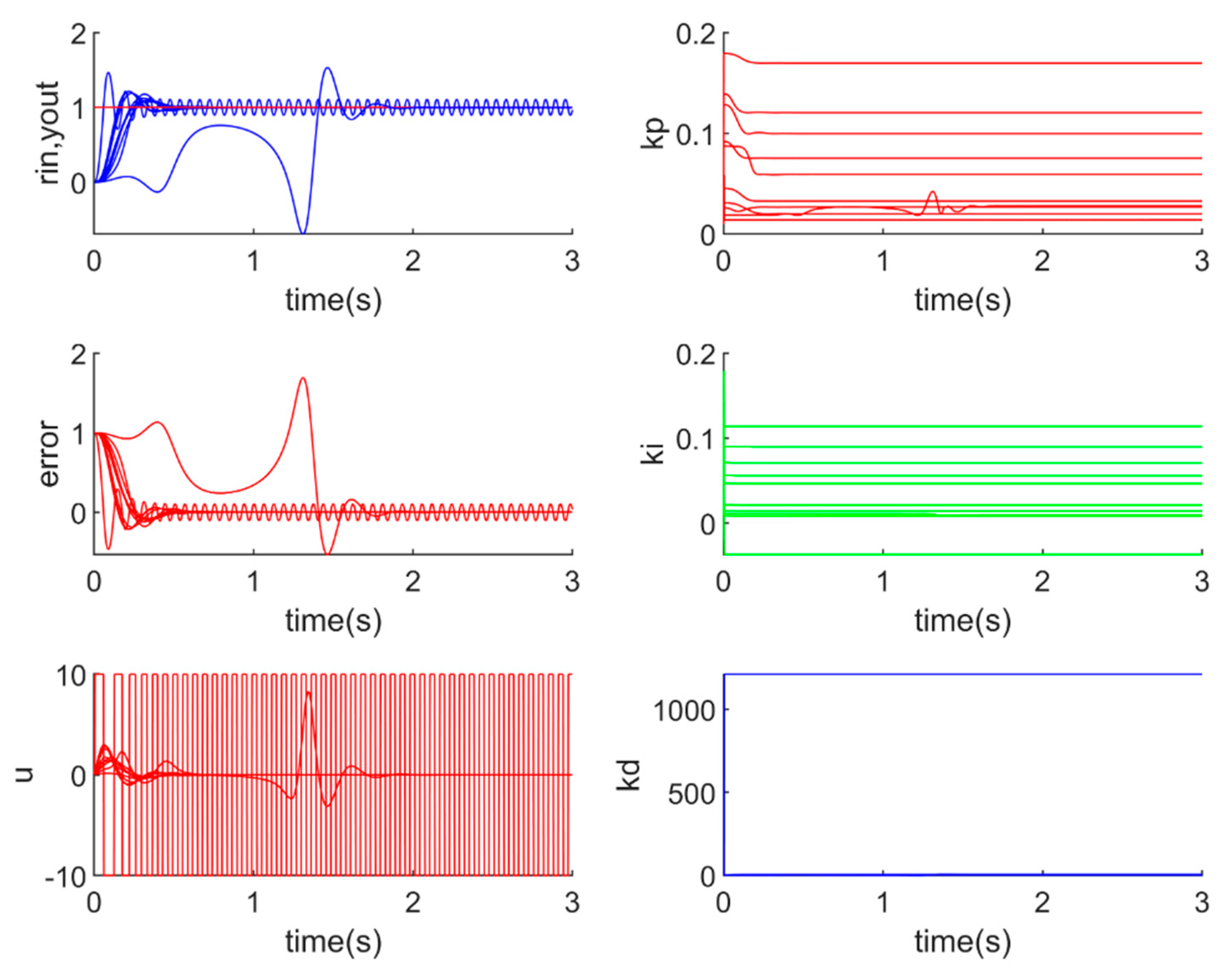
RBFNN-PID is another AI-CC system that is very unstable. Some of simulation results of RBFNN-PID are not convergent (the control results are unstable). The unstable results of RBFNN-PID are shown in Figure 11.
2.
AI-CC-S method is proposed
The AI-CC-S method is based on the equivalent criterion of the Nyquist stability criterion. All the control parameters that are adjusted by the AI-CC method should be judged according to the AI-CC-S method.
For example, if the controlled object model can be drawn as G O b j ( s ) = 200 s 2 + 30 s + 1 · e s , the controller model is G C t r ( s ) =   k p + k i s + k d · s = k d · s 2 + k p · s + k i s   ,   and the current time is t. The current parameters at time t are as follows: K p ( t ) = 2 ,   K i ( t ) = 0.2 , and   K d ( t ) = 0.2 , which are pretested to make the system run steadily.
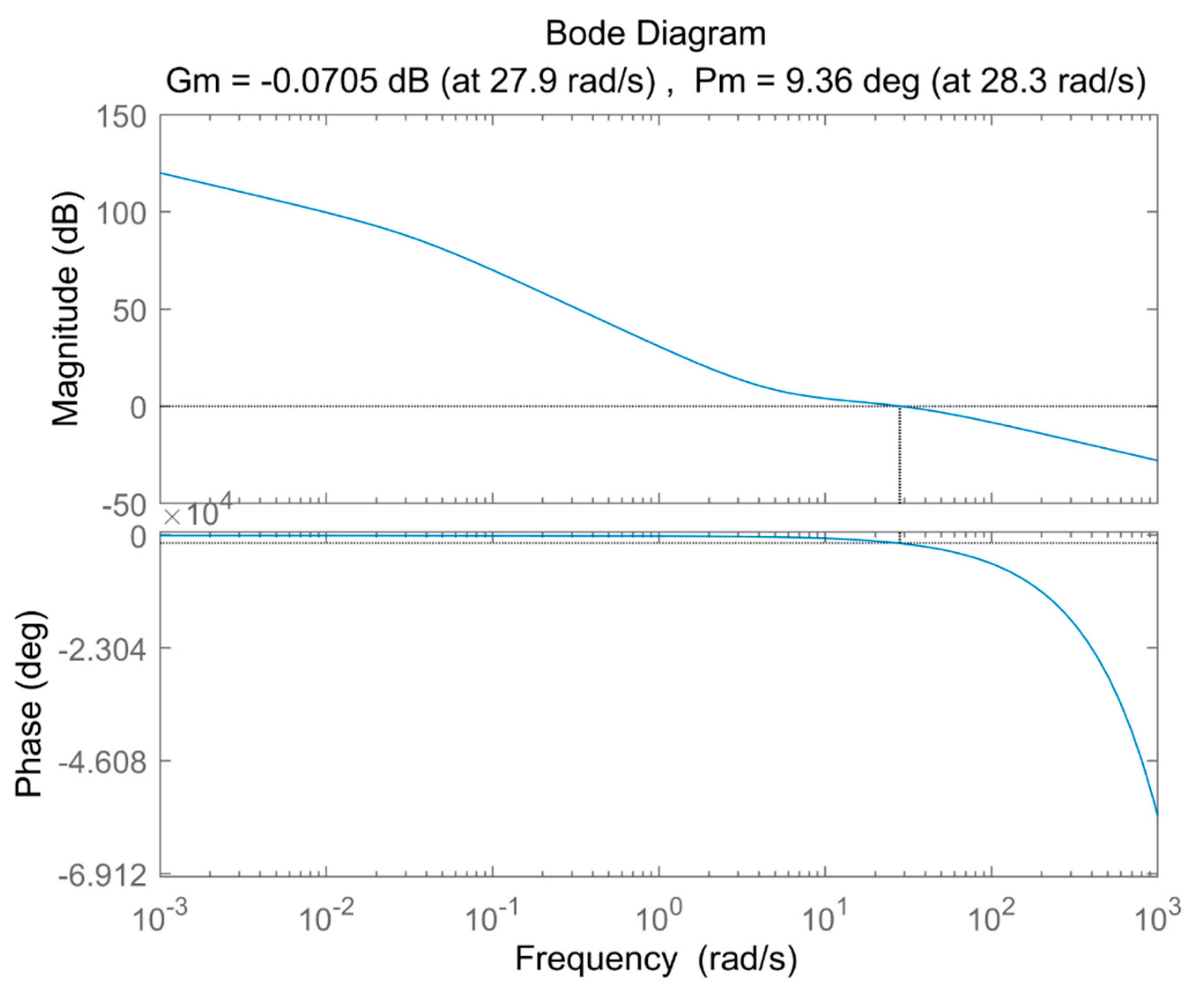
As the open-loop transfer function is G O p e n ( s ) , the amplitude margin can be calculated as G m = 20 · l o g 10 ( g m ) = 0.156 dB < 0 , and the phase margin can be calculated as P m = p m = 9.36 deg > π .
In each AC, amplitude and phase are calculated, the pseudocode is provided as follows, which can be implemented by different programming languages:
sys=tf(200,[1,30,1],’inputdelay’,1);
sys_pid=tf([kd2bc,kp2bc,ki2bc],[1,0]);
sys_open=sys*sys_pid;
[bode_mag,bode_phase,bode_w]=bode(sys_open);
[bode_gm,bode_pm,bode_wcg,bode_wcp]=margin(bode_mag,bode_phase,bode_w);
		
The bode plots of the control system with the latest K p ( t ) ,   K i ( t ) , K d ( t ) can be plotted, as in Figure 12. According to the above theoretical analysis, the current online-tuned parameters K p ( t ) ,   K i ( t ) , K d ( t ) . can make the system work steadily, so the current online-tuned parameters K p ( t ) ,   K i ( t ) , K d ( t ) can be adopted (not abandoned) for the PID controller.
3.
RBFNN-S-PID is proposed
RBFNN-S-PID is a method of RBFNN-PID composed with the AI-CC-S method. The effect of the improved RBFNN-S-PID method is shown in Figure 13.
Comparing Figure 11 with Figure 13, the RBFNN-S-PID system is much more stable: (1) All the RBFNN-S-PID results are convergent (finally stabilized); (2) RBFNN-S-PID has fewer disadvantages.
Throughout the online-tuning process, all updated parameters are judged. RBFNN-PID is unstable, but RBFNN-S-PID with the AI-CC-S method is stable. From the above theoretical analysis and simulation, the stability problem is solved.

7. Conclusions

In this study, three AI-CC methods (EA-PID, FA-PID, and WNN-PID) are proposed, and theoretical analysis for the stability of the above methods and stability guarantee methods are provided. Then, problems of manual-based methods are solved, and the performance of existing AI-CC methods is improved.
Comparative simulation results among E-PID, EA-PID, F-PID, FA-PID, BPNN-PID, RBFNN-PID, and WNN-PID methods are summarized in Table 10.
Comparative indicators are designed as follows: the control speed characteristic is measured by the Tr and Ts indicators. The capability of output-tracking input is measured by steady-state error. Contents of parameter configuration work, workload, and operating time are estimated, hence the intelligence level of the AI-CC system and the ability requirements for engineers can be evaluated.
According to Table 10, the conclusions of this study can be summarized as follows:
  • All AI-CC methods completed the control parameter online-tuning process (100% stable and convergence) except RBFNN-PID. The unstable problem of RBFNN-PID can be solved by the stability guarantee algorithm proposed in this study.
  • The control speed of EA-PID is the fastest (average T r = 94 and average T s = 293 are the smallest values). FA-PID (average T r = 102, average T s = 469) is better than F-PID (average T r = 158, average T s = 519). WNN-PID (average T r = 155, min Tr = 106, min T s = 468) is better than BPNN-PID (average T r = 192, min T r = 146, min T s = 602).
  • Stability of EA-PID is the best (average steady-state error = 0.000977 is the smallest value). FA-PID (average steady-state error = 0.004536) is better than F-PID (average steady-state error = 0.006044).
  • The robust (anti-interference) feature of most AI-CC methods is acceptable except RBFNN-PID: the problem of RBFNN-PID can be solved by adding the stability guarantee algorithm; other AI-CC systems can recover steady-state after interference. EA-PID has the fastest speed of recovery (average recovery time is 75, which is the smallest value).
  • The stability guarantee algorithm is effective for all AI-CC methods. Most AI-CC methods are stable (100% convergence) except RBFNN-PID, but RBFNN-S-PID (RBFNN-PID with stability guarantee algorithm) is stable. Therefore, the AI-CC method with the stability guarantee algorithm proposed in this study can be widely applied.
  • Parameter configuration work for engineers: E-PID and F-PID methods require precise configuration for parameters. E-PID determines parameters by querying the rule table. EA-PID and FA-PID methods decide parameters by querying an improved rule table and making calculations. For the above XNN-PID, engineers need to set the initial control parameters by experience or use the default values and design some parameters, like the number of hidden layers, the number of neurons in each layer, and the choice of the performance function. Then, the system will optimize and tune parameters in the online running process.
In the future, (1) variations of the industrial applications of PID systems will be upgraded to EA-PID, FA-PID, and WNN-PID systems in order to verify their practicability and feasibility in reality and the industrial environment. (2) Performance in factors such as faster control speed and lower steady-state error will be improved by adopting deep learning and predictive methods, namely, AI methods to AI-CC methods. (3) Performance between the simulated system and a real one will be compared, and results will be presented.

Author Contributions

Conceptualization, J.L.; methodology, J.L.; software, J.L.; validation, T.L. and J.L.; writing-original draft preparation, J.C. and F.Z.; writing-review and editing, T.L., J.C., J.L., and F.Z.; supervision, T.L. and J.C. All authors have read and agreed to the published version of the manuscript.

Funding

Reform and innovation project of undergraduate teaching of beijing in 2019 (No.202). Philosophy and Social Science Foundation of Beijing (16JDYJB028). Reserve subject leader project of capital university of economics.

Conflicts of Interest

The authors declare no conflict of interest.

References

  1. Åström, K.J.; Hägglund, T. The future of PID control. Control Eng. Pract. 2001, 9, 1163–1175. [Google Scholar] [CrossRef]
  2. Pritesh, S.; Agashe, S. Review of fractional PID controller. Mechatronics 2016, 38, 29–41. [Google Scholar]
  3. Hang, C.C.; Astrom, K.J.; Wang, Q.G. Relay feedback auto-tuning of process controllers—A tutorial review. J. Process. Control 2002, 12, 143–162. [Google Scholar] [CrossRef]
  4. Berner, J.; Hägglund, T.; Åström, K.J. Asymmetric relay autotuning—Practical features for industrial use. Control Eng. Pract. 2016, 54, 231–245. [Google Scholar] [CrossRef]
  5. Soltesz, K.; Mercader, P.; Banos, A. An automatic tuner with short experiment and probabilistic plant parameterization. Int. J. Robust Nonlinear Control 2017, 27, 1857–1873. [Google Scholar] [CrossRef] [Green Version]
  6. Carlucho, I.; de Paula, M.; Villar, S.A.; Acosta, G.G. Incremental q-learning strategy for adaptive pid control of mobile robots. Expert Syst. Appl. 2017, 80, 183–199. [Google Scholar] [CrossRef]
  7. Cortes, P.; Kazmierkowski, M.P.; Kennel, R.M.; Quevedo, D.E.; Rodriguez, J. Predictive control in power electronics and drives. IEEE Trans. Ind. Electron. 2008, 55, 4312–4324. [Google Scholar] [CrossRef]
  8. Howe, R.; Faber, H.; Casey, B. Occupational health and safety-a key engineering design consideration for botanical resources australia pty ltd. In I International Symposium on Pyrethrum, The Natural Insecticide: Scientific and Industrial Developments in the Renewal of a 1073; ISHS: Leuven, Belgium, 2011; pp. 79–84. [Google Scholar]
  9. Mnih, V.; Kavukcuoglu, K.; Silver, D.; Rusu, A.A.; Veness, J.; Bellemare, M.G.; Petersen, S. Human-level control through deep reinforcement learning. Nature 2015, 518, 529–533. [Google Scholar] [CrossRef] [PubMed]
  10. Vassilyev, S.N.; Kelina, A.Y.; Kudinov, Y.I.; Pashchenko, F.F. Intelligent control systems. Procedia Comput. Sci. 2017, 103, 623–628. [Google Scholar] [CrossRef]
  11. Delean, B. Computerized Driverless Vehicles and Traffic Control System. U.S. Patent No. 8,090,489, 3 January 2012. [Google Scholar]
  12. Schmidhuber, J. Deep learning in neural networks: An overview. Neural Netw. 2015, 61, 85–117. [Google Scholar] [CrossRef] [PubMed] [Green Version]
  13. Goodfellow, I.; Bengio, Y.; Courville, A. Deep Learning; MIT Press: Cambridge, MA, USA, 2016. [Google Scholar]
  14. Sutton, R.S.; Barto, A.G. Reinforcement Learning: An Introduction; MIT Press: Cambridge, MA, USA, 2018. [Google Scholar]
  15. Tzafestas, S.; Papanikolopoulos, N.P. Incremental fuzzy expert PID control. IEEE Trans. Ind. Electron. 1990, 37, 365–371. [Google Scholar] [CrossRef]
  16. Mayne, D.Q. Model predictive control: Recent developments and future promise. Automatica 2014, 50, 2967–2986. [Google Scholar] [CrossRef]
  17. Borrelli, F.; Bemporad, A.; Morari, M. Predictive Control for Linear and Hybrid Systems; Cambridge University Press: Cambridge, UK, 2017. [Google Scholar]
  18. Krogh, A.; Vedelsby, J. Neural network ensembles, cross validation, and active learning. In Advances in Neural Information Processing Systems; MIT Press: Cambridge, MA, USA, 1995; pp. 231–238. [Google Scholar]
  19. Bellman, R.E. Adaptive Control Processes: A Guided Tour; Princeton University Press: Princeton, NJ, USA, 2015; Volume 2045. [Google Scholar]
  20. Zhao, W.B.B.; Zhenfan, L.T. Neural network based online self-learning adaptive PID control. In Proceedings of the 3rd World Congress on Intelligent Control and Automation, Hefei, China, 26 June–2 July 2000; IEEE: Piscataway, NJ, USA, 2000; Volume 2, pp. 908–910. [Google Scholar]
  21. Sharifian, M.B.B.; Mirlo, A.; Tavoosi, J.; Sabahi, M. Self-adaptive RBF neural network PID controller in linear elevator. In Proceedings of the 2011 International Conference on Electrical Machines and Systems, Beijing, China, 20–23 August 2011; IEEE: Piscataway, NJ, USA, 2011; pp. 1–4. [Google Scholar]
  22. Chen, H.Y.; Liang, J.W. Piezoelectric-actuated drop-on-demand droplet generator control using adaptive wavelet neural network controller. J. Process Control 2014, 24, 578–585. [Google Scholar] [CrossRef]
  23. Kang, F.; Liang, Y.B. Research on modeling and simulation of expert pid controlled servo system based on matlab/s-function. In Applied Mechanics and Materials; Trans Tech Publ: Stafa-Zurich, Switzerland, 2013; Volume 347, pp. 604–609. [Google Scholar]
  24. Ji, Y.L.; Sun, Y.L.; Wen, F. Robot Arm Motion Control Based on Trapezoidal Fuzzy PID Algorithm. Basic Clin. Pharmacol. Toxicol. 2020, 126, 193–194. [Google Scholar]
  25. González-Briones, A.; Prieto, J.; de la Prieta, F.; Herrera-Viedma, E.; Corchado, J.M. Energy optimization using a case-based reasoning strategy. Sensors 2018, 18, 865. [Google Scholar] [CrossRef] [PubMed] [Green Version]
  26. González-Briones, A.; Chamoso, P.; Yoe, H.; Corchado, J.M. GreenVMAS: Virtual organization based platform for heating greenhouses using waste energy from power plants. Sensors 2018, 18, 861. [Google Scholar] [CrossRef] [PubMed] [Green Version]
  27. Sergio, A.; Carvalho, S.; Marco, R.E.G.O. On the Use of Compact Approaches in Evolution Strategies. ADCAIJ Adv. Distrib. Comput. Artif. Intell. J. 2014, 3, 13–23. [Google Scholar]
Figure 1. System structure of classical proportion integration differentiation (PID) control systems.
Processes 08 01042 g001
Figure 2. System structure of E-PID (proportion integration differentiation controller based on expert system)and F-PID (proportion integration differentiation controller based on fuzzy calculation)systems.
Processes 08 01042 g002
Figure 3. Heating control system with E-PID (expert system based proportion integration differentiation controller) and F-PID (fuzzy calculation based proportion integration differentiation controller) methods.
Processes 08 01042 g003
Figure 4. System structure of EA-PID (Definition 3) and FA-PID (Definition 4) methods.
Processes 08 01042 g004
Figure 5. Design of fuzzy controller: (a) F-PID fuzzy controller parameter setting; (b) FA-PID fuzzy controller parameter setting.
Processes 08 01042 g005aProcesses 08 01042 g005b
Figure 6. Structure of neural-network-based intelligent control system.
Processes 08 01042 g006
Figure 7. Simulation results of saturation tests of four AI-CC systems.
Processes 08 01042 g007
Figure 8. Results of the situation of unsaturation of four AI-CC systems.
Processes 08 01042 g008
Figure 9. 1 SC and 10 SCs simulations for each algorithm: (a) 1 SC and 10 SCs simulation results of BPNN-PID; (b) 1 SC and 10 SCs simulation results of RBFNN-PID; (c) 1 SC and 10 SCs simulation results of WNN-PID.
Processes 08 01042 g009aProcesses 08 01042 g009bProcesses 08 01042 g009c
Figure 10. Comparison for robust (anti-interference) analysis: (a) BPNN-PID; (b) WNN-PID; (c) RBFNN-PID; (d) RBFNN-S-PID; (e) E-PID; (f) EA-PID; (g) F-PID; (h) FA-PID.
Processes 08 01042 g010aProcesses 08 01042 g010b
Figure 11. 10 SCs simulation for unstable RBFNN-PID systems.
Processes 08 01042 g011
Figure 12. Result of Bode plot.
Processes 08 01042 g012
Figure 13. 10 SCs simulation for unstable RBFNN-PID-S systems.
Processes 08 01042 g013
Table 1. Expert rule table.
| e | E h i g h E l o w | e | < E h i g h 0 | e | < E l o w
| e c | E C h i g h R h h R m h R l h
E C l o w | e c | < E C h i g h R h m R m m R l m
0 | e c | < E C l o w R h l R m l R l l
Table 2. Expert rule table of EA-PID for parameter K p .
R K p E A ( e ( k ) , e c ( k ) ) | e | E h i g h E l o w | e | < E h i g h 0 | e | < E l o w
| e c | E C h i g h 10.9980.998
E C l o w | e c | < E C h i g h 1.00211
0 | e c | < E C l o w 1.0041.0021
Table 3. Expert rule table of EA-PID for parameter K i .
R K p E A ( e ( k ) , e c ( k ) ) | e | E h i g h E l o w | e | < E h i g h 0 | e | < E l o w
| e c | E C h i g h 10.9980.998
E C l o w | e c | < E C h i g h 1.00211
0 | e c | < E C l o w 1.0041.0021
Table 4. Expert rule table of EA-PID for parameter K d .
R K p E A ( e ( k ) , e c ( k ) ) | e | E h i g h E l o w | e | < E h i g h 0 | e | < E l o w
| e c | E C h i g h 1.0021.0021.002
E C l o w | e c | < E C h i g h 111
0 | e c | < E C l o w 0.9980.9980.998
Table 5. Comparison between F-PID, E-PID, FA-PID, and EA-PID methods.
E-PIDEA-PIDF-PIDFA-PID
Online-tuning principlesnew PID parameters are obtained directly from the rule tablenew PID parameters at time k are calculated by old PID parameters at time k 1 with change ratio from the rule tablenew PID parameters are obtained directly from fuzzy computing new PID parameters at time k are calculated by old PID parameters at time k 1 with a change ratio from fuzzy computing
Online tuning calculationsexpert rule tableexpert rule tablefuzzy computingfuzzy computing
Output calculationsPID parameters: R K p E ( e ( k ) , e c ( k ) ) Change ratio for PID parameters: R K p E A ( e ( k ) , e c ( k ) ) PID parameters: R K p F ( e ( k ) , e c ( k ) ) Change ratio for PID parameters: R K p F A ( e ( k ) , e c ( k ) )
Tuning results K p ( t ) = R K p E ( t ) K p ( t ) = K p ( t 1 ) · R K p E ( t ) K p ( k ) = R K p F ( k ) . K p ( t ) = K p ( t 1 ) · R K p F A ( t )
Table 6. Comparison of simulation results of control system output.
Comparison→
Method↓
Rise Time TrSettling Time TsOvershootSteady-State ErrorDeviation from Steady-StateRecovery Time
E-PIDfastest (180)fast (600)Nolargest (1.0%)worst (20.3%)slowest (1000)
EA-PIDfast (200)fastest (330)Yes (0.2%)smallest (0.1%)best (16.1%)fastest (275)
F-PIDslowest (340)slowest (630)Nolarge (0.6%)good (18.7%)fast (515)
FA-PIDslow (260)slow (610)Nosmall (0.5%)bad (19.7%)slow (700)
Table 7. Rise time, settling time, steady-state error statistic of 30 simulations.
Comparison→
SC Number↓
BPNN
-PID
Tr
BPNN
-PID
Ts
BPNN
-PID
St-Err
RBFNN
-PID
Tr
RBFNN
-PID
Ts
RBFNN
-PID
St-Err
WNN
-PID
Tr
WNN
-PID
Ts
WNN
-PID
St-Err
120212570.0099551073000.0045371738900.012301
22289790.0075761022650.0042081739590.013048
32629720.0072281322720.00258625711160.01006
302609630.00708123112120.01884725912280.080704
minimum1325120.00662996 (unstable)221 (unstable)0.000567110 (improved)495 (improved)0.006963
mean2309260.007537152 (unstable)372 (unstable)0.026832166 (improved)849 (improved)0.018646
maximum50219690.013868846 (unstable)1212 (unstable)0.694877259 (improved)1370 (improved)0.080704 (improved)
Table 8. Average results of the above three groups of simulations.
Comparison→
SC Number↓
BPNN
-PID
T r
BPNN
-PID
St-Err
RBFNN
-PID
T r
RBFNN
-PID
T s
RBFNN-PID
St-Err
WNN
-PID
T r
WNN
-PID
T s
WNN
-PID
St-Err
Group 1217.60.007525148.7422.30.050000177.6877.30.020540
Group 2228.90.007318108.2302.50.003189173.1893.30.016462
Group 3213.30.007746160.1407.70.050725157.3789.10.01
Table 9. Comparison of different intelligent control systems.
Comparative Item→
Method↓
Mean of Rise TimeMean of Settling TimeMean of Steady-State ErrorMinimum of Rise TimeMinimum of Settling TimeMinimum of Steady-State Error
E-PID943260.008839943260.008839
(Fastest)(Fastest)
EA-PID942930.000977942930.000977
(Fastest)(Fastest)(smallest)(Fastest)(Fastest)(smallest)
F-PID1585190.0060441585190.006044
FA-PID1024690.0045361024690.004536
(improved)(improved)(improved)(improved)(improved)(improved)
BPNN-PID1928040.0080341466020.006708
RBFNN-PID1343870.00416972220.001666
(Unstable)(Unstable)(Unstable)(Unstable)(Unstable)(Unstable)
WNN-PID1558260.0160761064680.00741
(improved)(improved)(improved)
Table 10. Comparison of different intelligent control systems.
Method→
Comparative Item↓
E-PIDEA-PIDF-PIDFA-PIDBPNN-PIDRBFNN-PIDWNN-PID
Stable (Convergence)All stableAll stableAll stableAll stableAll stable90% stable
(100% stable in RBFNN-S-PID)
All stable
Control Speed
(means of T r and T s )
[minimum of T r and T s ]
(94,326)
[same as ↑]
Fastest
(94,293)
[same as ↑]
(158,519)
[same as ↑]
Better than F-PID (102,469)
[same as ↑]
(192,804)
[146,602]
Not be compared because unstableSome are better than BPNN-PID
(155,826)
[106,468]
Steady-state error (means)(0.008839)Best
(0.000977)
(0.006044)Better than F-PID
(0.004536)
(0.008034)Not be compared because unstable(0.007410)
Anti-interference (means of recover time)(781)Best
(75)
(301)(468)(1135)Not be compared because unstable(2037)
Stability analysis
(Convergence)
Stable: 100% convergenceStable: 100% convergenceStable: 100% convergenceStable: 100% convergenceStable: 100% convergenceUnstable, RBFNN-S-PID is stableStable: 100% convergence
Parameters configuration
work for engineers
Fill in expert rule table for K p i d E Expert rule table for R p i d E A and Any stable K p i d Fuzzy and defuzzy rules for K p i d F Fuzzy rules for R p i d F A and Any stable K p i d design and train neural networkdesign and train neural networkdesign and train neural network