Article

Numerical Investigation on the Sieving Performance of Elliptical Vibrating Screen

1
College of Mechanical Engineering and Automation, Huaqiao University, Xiamen 361021, China
2
Fujian Key Laboratory of Digital Equipment, Fujian University of Technology, Fuzhou 350118, China
*
Author to whom correspondence should be addressed.
Processes 2020, 8(9), 1151; https://doi.org/10.3390/pr8091151
Submission received: 11 July 2020 / Revised: 7 September 2020 / Accepted: 11 September 2020 / Published: 14 September 2020
(This article belongs to the Section Process Control and Monitoring)

Abstract

:
Screening techniques have been widely deployed in industrial production for the size-separation of granular materials such as coal. The elliptical vibrating screen has been regarded as an excellent screening apparatus in terms of its high screening efficiency and large processing capacity. However, its fundamental mechanisms and operational principles remain poorly understood. In this paper, the sieving process of an elliptical vibrating screen was numerically simulated based on the discrete element method (DEM), and an approach coupling the DEM and the finite element method (DEM–FEM) was introduced to further explore the collision impact of materials on the screen deck. The screening time, screening efficiency, maximum stress and maximum deformation were examined for the evaluation of sieving performance. The effects of six parameters—length of the semi-major axis, length ratio between two semi-axes, vibration frequency, inclination angle, vibration direction angle and vibration direction—on different sieving results were systematically investigated in univariate and multivariate experiments. Additionally, the relationships among the four performance indexes were discussed and the relational functions were obtained. The conclusions and methodologies presented in this work could be of great significance for the design and improvement of elliptical vibrating screens.

1. Introduction

Particulate and granular materials such as coal, cereals and tablets are ubiquitous in natural environments and industrial engineering. As a dominant fossil fuel, coal accounts for 30% of all natural energy resources [1]. In China, the coal industry has developed rapidly, with China’s production and consumption of coal respectively accounting for about 46% and 49% of world production [2]. However, the traditional utilization of coal materials has encountered a serious problem in the form of air pollutant emissions and solid waste generation. Accordingly, clean coal technology was introduced for the reduction of pollution issues, and screening is an indispensable technique for coal processing. The vibrating screen is considered an effective screening apparatus, usually classifying granular materials according to their size, and has been extensively adopted in mineral production. In accordance with the motion trajectory of the screen deck, vibrating screens can be classified into three typical types: linear vibrating screens, elliptical vibrating screens and circular vibrating screens [3]. Screening efficiency and processing capacity are the two crucial indexes for the evaluation of sieving performance. A vibrating screen with high screening efficiency can prevent the need for reprocessing work, and a large processing capacity is conducive to the reduction of energy expenditure.
The complicated dynamics of granular materials have sparked intense interest among researchers. Scholars have devoted extensive efforts to exploring the motion behaviors and the fluid-like characteristics of particles; however, observing and recording massive particles can be difficult and time-consuming. The discrete element method (DEM), a numerical modeling method originally proposed by P. A. Cundall, has been adopted for investigating the mechanical behavior of granular assemblies [4]. The significant improvement of DEM in recent years was encouraged by the development of advanced computational technologies and algorithms, which greatly boosted the wide applications of DEM in various fields, including agriculture [5], the mineral industry [6] and chemical engineering [7]. Moreover, the method was gradually applied for the exploration of more complicated phenomena such as multi-phase flow [8,9].
In recent years, an increasing number of researchers commenced numerical investigations of the sieving process of vibrating screens based on DEM. Wang et al. studied the effect of screen length on the screening efficiency of vibrating screens under various parameter conditions [10]. Cleary et al. investigated the particle flow and separation performance of a banana screen [11,12]. Jahani et al. addressed the impact of several operational parameters on the performance of an inclined vibrating pilot-scale screen using the LIGGGHTS code [13]. Wang et al. presented the relationships between vibration parameters and several evaluation indexes [14]. Jafari et al. explored the influence of different parameters on the screening efficiency and wearing status [15]. Some other structural factors, such as particle shape [16] and aperture shape [17], have also been discussed. Additionally, the optimal combination of operating parameters also has been a hot research topic. One of the most efficient and time-saving methods is the Taguchi orthogonal design, a widespread experimental technique, introduced for the parameter optimization of linear and circular vibrating screens [14,18]. The reliability of DEM simulation has been effectively verified by the corresponding physical experiments [19,20,21].
The elliptical vibrating screen integrates the merits of linear vibrating screens and circular vibrating screens; its screening efficiency and ability to transport materials largely outweigh those of the other two kinds of screen [22]. Nevertheless, previous studies have mainly concentrated on linear and circular vibrating screens, whereas the operational mechanisms of elliptical vibrating screens have not yet received an effective demonstration. Meanwhile, most studies have been mainly devoted to the improvement of screening efficiency, whereas the significance of processing capacity has been ignored. Therefore, an in-depth analysis on the sieving performance of elliptical vibrating screens should be carried out.
In this work, the sieving processes of an elliptical vibrating screen with various technical parameters was numerically simulated based on DEM. Moreover, noting that the screen mesh is traditionally made of metal, which easily suffers from plastic deformation or even serious damage due to the continuous impact of the feeding material, DEM was extended and coupled with the finite element method (FEM) to further analyze the fatigue phenomena of the screen deck. The effects of sieving parameters on the performance indexes were discussed in single-factor experiments and orthogonal experiments.

2. Sieving Characteristics

2.1. Kinetic Analysis of the Screen

Apart from the vibration trace, a vibrating screen can also be classified by the number of excitation shafts. The structure of a twin-shaft elliptical vibrating screen is rather sophisticated, but the functional components consist mainly of the screen box, vibration exciters and supporting springs, as illustrated in Figure 1. Each excitation shaft is installed with a set of eccentric blocks, and both shafts are powered by a pair of synchronous gears rotating in opposite directions with the same angular speed ω and maintaining a relatively stable difference between the phase angles φ 1 and φ 2 of the eccentric blocks. In contrast with the twin-shaft linear vibrating screen, the masses m 1 and m 2 of the eccentric blocks on the revolving shafts of the elliptical vibrating screen are divergent. When this kind of screening equipment is activated, a centrifugal force is generated, causing the screen box to move with an elliptical trajectory.
Though the operation principle of the vibration of the screen box is complicated, the ultimate objective invariably comes down to the realization of an ideal vibration trajectory. The simplified elliptical trace of the screen deck can be described by
{ x = A x cos ( ω t + φ x ) y = A y cos ( ω t + φ y )
where x and y are the horizontal and vertical displacement, A x and A y are the amplitudes of simple harmonic motions, ω is the angular velocity, t is time, and φ x and φ y are the initial phase angles. Particularly, it is a right elliptical trace with clockwise motion when the initial phase difference φ y φ x = π / 2 , whereas it becomes a right elliptical trace with anticlockwise motion when φ y φ x = π / 2 . In both conditions, A x and A y are respectively equal to the semi-major axis a and the semi-minor axis b . Taking the right elliptical trace with clockwise motion, for example, then Equation (1) is translated as follows:
{ x = a · cos ω t y = b · sin ω t
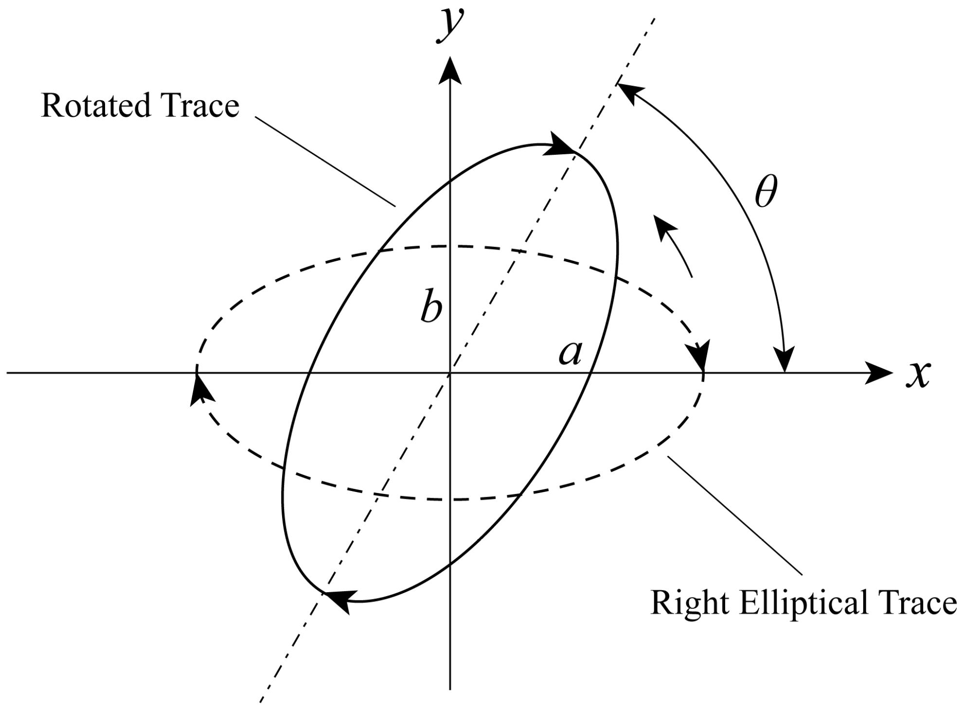
As illustrated in Figure 2, in order to directly express the equations of elliptical vibration with the given parameters a and b , any elliptical trace can be calculated by spinning the right ellipse counter-clockwise around the origin for θ degrees.
To summarize, the elliptical vibration trace can be expressed uniformly by
{ x = A x · sin ( ω t + φ x ) y = A y · sin ( ω t + φ y )
where the horizontal and vertical amplitudes A x and A y of the two kinds of traces with opposite directions hold
{ A x = ( a cos θ ) 2 + ( b sin θ ) 2 A y = ( a sin θ ) 2 + ( b cos θ ) 2
and the only disparity between both vibration modes rests with the initial phase angles, which are respectively represented by Equation (5) for the clockwise mode and Equation (6) for the anticlockwise mode.
{ φ x 0 = arctan ( a b · cot θ ) φ y 0 = arctan ( a b tan θ )
{ φ x 1 = arctan ( b a tan θ ) φ y 1 = arctan ( b a cot θ )
Therefore, the velocity and acceleration of the screen deck can be respectively calculated by Equations (7) and (8), which is described as follows:
{ v x = A x ω cos ( ω t + φ x ) v y = A y ω cos ( ω t + φ y )
{ a x = A x ω 2 sin ( ω t + φ x ) a y = A y ω 2 sin ( ω t + φ y )

2.2. Motion Analysis of Particle

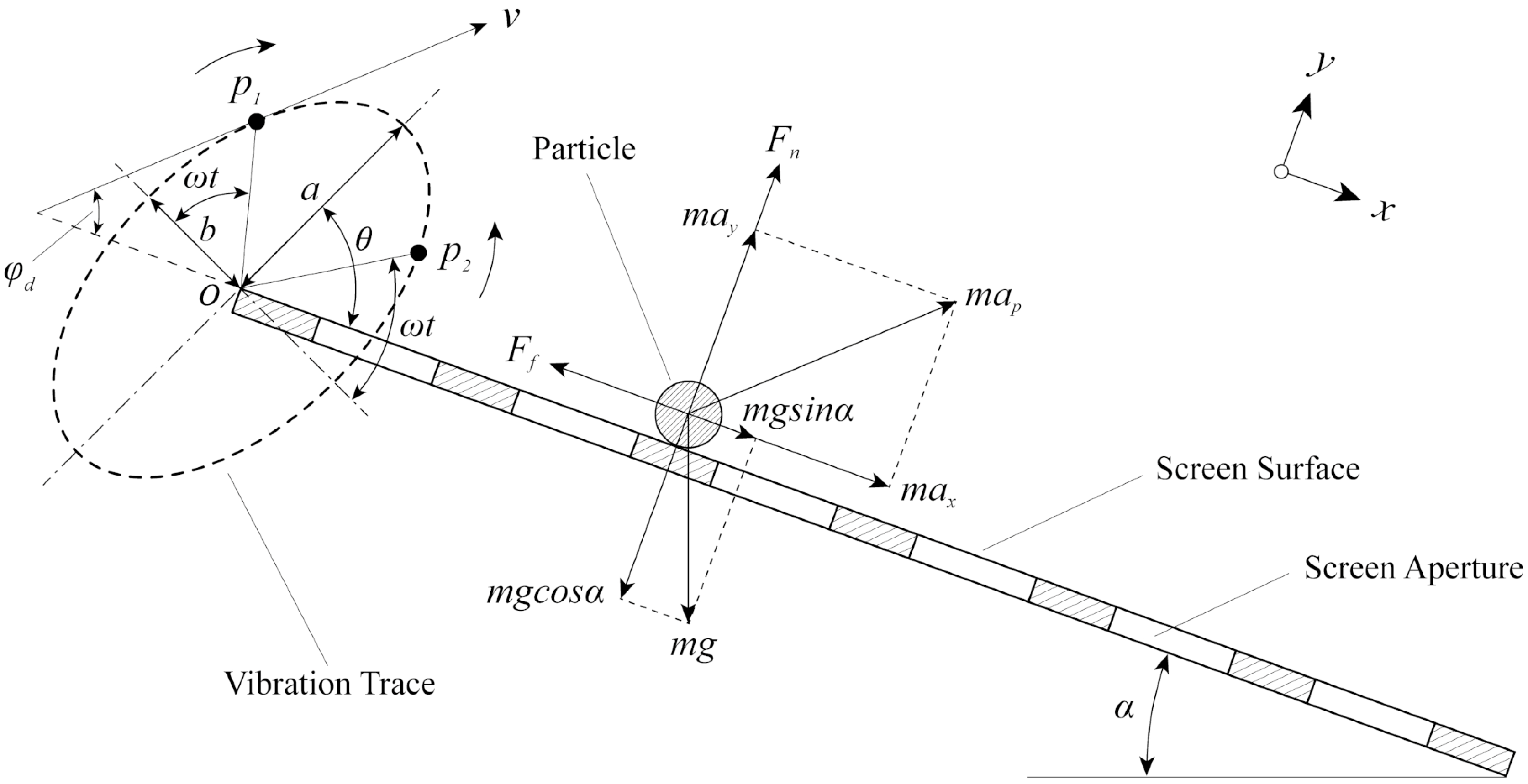
The vibration characteristics of the screen deck and the forces acting on an individual particle are exhibited in Figure 3, where α denotes the inclination angle of screen deck, a and b are respectively the length of semi-major axis and the semi-minor axis of the elliptical trace, θ is the vibration direction angle, ω is the angular velocity, t is time, and p 1 and p 2 are the virtual positions of screen which move along the clockwise and the anticlockwise trace, respectively.
When the screen deck stays exactly at the point p 1 during the vibrating motion, the equilibrium equations of forces acting on the particle which collides with the screen surface give
{ m a x = m g sin α F f m a y = F n m g cos α
where m is the mass of particle, g is the gravitational acceleration, F f is the frictional force between the particle and screen surface, and F n is the positive pressure. φ d is the throwing angle between the throwing direction and the screen surface. Notably, the throwing angle of the elliptical vibration system changes all the time, which is quite different from that of the linear vibration system. Assuming that the particle collides with the screen plane and is about to leave at the time t d , the prerequisite for this particle to be thrown away from the surface is F n = 0 , hence the equation in the perpendicular direction of screen deck can be simplified as:
A y ω 2 sin ( ω t d + φ y ) = g cos α
where ω t d is the rotated angle of the screen as the particle leaves. Hence, the theoretical throwing intensity K v [23], which is usually adopted for the design of vibration machinery, can be calculated by
K v = A y ω 2 g cos α = 4 π 2 f 2 ( a sin θ ) 2 + ( b cos θ ) 2 g cos α
where f is the vibration frequency. When K v = 1 , the particle maintains close contact with the screen deck in the form of sliding. If K v > 1 , this signifies that the particle has sufficient energy to be ejected from the screen surface. After a period of the parabolic motion caused by the ejection function of the screen deck, the particle dashes on the screen surface again at the time t d e . Assuming that Δ x is the horizontal displacement of the throwing process, then the total rotating angle during a period of throwing can be obtained as follows:
θ d = ω ( t d e t d )
Consequently, the theoretical average velocity v ¯ d x of a particle along the length direction of screen deck can be calculated by
v ¯ d x = Δ x 2 π / ω = A x ω 2 π [ sin ( ω t d + φ x ) ( 1 cos θ d ) + cos ( ω t d + φ x ) ( θ d sin θ d ) ] + θ d 4 π K v A x ω tan α
and by substituting ω = 2 π f into Equation (13), the average velocity v ¯ d x can be reformulated as:
v ¯ d x = A x f [ sin ( 2 π t d f + φ x ) ( 1 cos θ d ) + cos ( 2 π t d f + φ x ) ( θ d sin θ d ) + θ d tan α 2 K v ]
Theoretically, a smaller velocity of the particle results in a greater chance of colliding with the screen surface, which then increases the opportunities for penetration. Nevertheless, the retention time of particles on screen surface rises simultaneously as the collision frequency increases, and eventually brings about the lower processing efficiency. According to Equations (11) and (14), the throwing condition and traveling velocity of particle are mainly determined by the length of the semi-major axis a , length of the semi-minor axis b , vibration frequency f , inclination angle α , vibration direction angle θ and the vibration direction of the screen deck.

3. Numerical Experiments

3.1. DEM Description

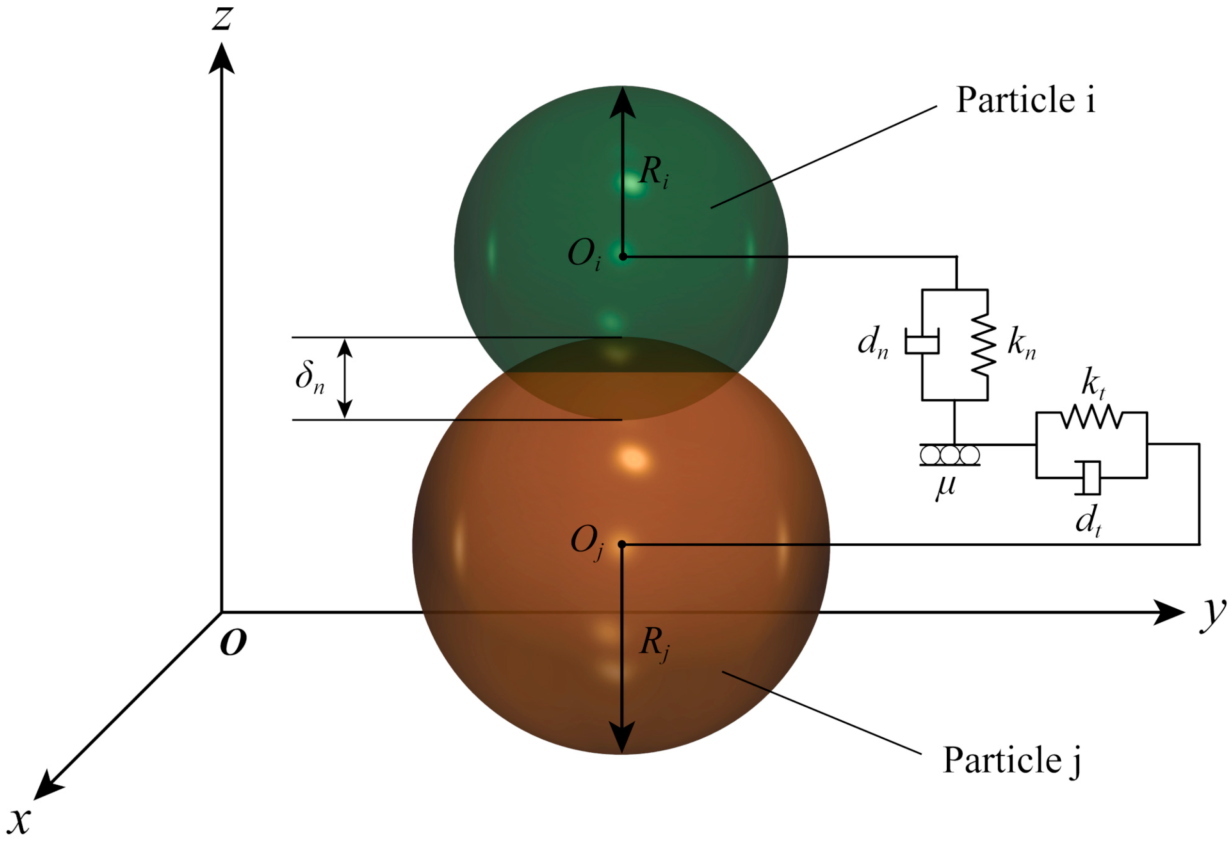
The contact model is the foundation of the DEM simulation, and directly determines the motion characteristics of the granular medium. The screening process of a vibrating screen is an exceedingly complicated phenomenon, which involves a large number of particles, thus a proper and efficient contact model could be beneficial for the successful execution of numerical experiments. As illustrated in Figure 4, the Hertz–Mindlin (no-slip) contact model was adopted in the present work. Both the particle–particle and particle–wall interactions were calculated based on this model, which fundamentally simplifies the contact forces between two particles into the springs (with normal stiffness k n and tangential stiffness k t ), dampers (with normal damping d n and tangential damping d t ) and a slider (with friction coefficient μ ). The normal force component is established based on the elastic theory of Hertz, and the no-slip tangential force is solved by Mindlin and Deresiewicz (hence the name Hertz–Mindlin) [24].
Taking the particle i for example, the Newton–Euler equations governing translational and rotational motion [25] are respectively defined by
m i d v i d t = j = 1 n i ( F c n , i j + F c t , i j + F d n , i j + F d t , i j ) + m i g
I i d ω i d t = j = 1 n i ( T t , i j + T r , i j )
where m i , I i , v i and ω i are respectively the mass, the moment of inertia, the translational velocity and the angular velocity of particle i , n i is the number of particles which contact with particle i , g is the gravitational acceleration, F c n , i j and F c t , i j are respectively the normal spring force and tangential spring force, F d n , i j and F d t , i j are respectively the normal damping force and tangential damping force, and T r , i j and T t , i j are the torques triggered by rolling friction and tangential forces, respectively. The specific calculation method of the forces and torques mentioned above can be found in [26].

3.2. Simulation Model

In order to reduce the complexity of the elliptical vibrating screen, realize the similar function of the actual machine and collect particle data conveniently, a simplified three-dimensional prototype, illustrated in Figure 5, was established for the DEM simulation of the sieving process. The geometric model of the vibrating screen is mainly composed of a virtual feed end, a movable screen deck, a stationary screen box and a recycle bin. For a better understanding of the penetration behavior of particles in different areas, the screen deck was evenly divided into five sections along the length direction.
The relative parameters of the granular material and geometric model are listed in Table 1 in detail. As discussed previously, the sieving performance of a vibrating screen is mainly determined by the motion characteristics of the screen deck. Therefore, six technical parameters of the elliptical vibration mode—the length of semi-major axis a , the length ratio between two semi-axes b / a , the vibration frequency f , the inclination angle α , the vibration direction angle θ and the vibration direction δ —of the screen deck were adjustable, whereas other factors remained constant in all the following experiments. In particular, the vibration direction δ of the screen deck is the sole discrete variable compared with the other five, and only contains two properties: the clockwise mode and the anticlockwise mode, represented by 0 and 1, respectively.
The particle shape, one of the inherent properties of feeding materials, also has an influence on the sieving results of the vibrating screen. However, the granular shape is immeasurable and hard to systematically investigate because modeling all the irregular shapes of mineral grains is impossible. Meanwhile, previous studies conducted by Lala Zhao et al. [18] and Xiaoyue Wang et al. [16] proved that the spherical and non-spherical particles exhibit similar influencing trends on sieving results by examining several kinds of non-spherical particles. Therefore, the particle shape is not taken into account in the present work—the particles used in the experiments are all spherical.
The material properties and collision coefficients, which are critical for keeping the modeling results as close to the reality as possible, are listed in Table 2 in detail. The particle properties are the same as sand, and the wall refers to all the steel components, including the screen deck, the screen box and the recycle bin. According to the given conditions, the sieving process of elliptical vibrating screen was numerically simulated based on the principle of DEM.
As exhibited in Figure 6, raw material denotes the unscreened particles on the screen surface, fine product refers to the screened material on the bottom of screen box, and overflowed material on the recycle bin is the crude product. During the sieving process, raw materials are continuously generated from the feed end and fall toward the screen surface under the action of gravity. In the beginning, a group of mixed and disorderly particles are stacked together in the left end of the screen, and then gradually diffuse, layer and travel along the length direction of screen deck under the influence of vibration. An individual particle, after experiencing several collisions with other particles, the screen surface or the inside walls of the screen box, would either pass through the screen mesh and finally reach the bottom of the screen box, or be transported to the discharge end and eventually overflow to the recycle bin with the particle swarm.
The feasibility of a particle being capable of passing through the screen aperture depends on both the particle diameter d and the aperture size l , hence the relative size k d of particles was introduced, which can be described by
k d = d l
and then an undersized particle refers to a particle of which the relative diameter k d is smaller than 1, which is contrary to the oversized particles. Ideally, the recycle bin is full of oversized particles, whereas the crude product is universally composed of partial undersized particles on account of the limitations of sieving performance.

3.3. Performance Evaluation

Generally, a productive screening machine is operated with high product quality and a large processing capacity. Therefore, the screening efficiency η and the screening time t were introduced for evaluating the product quality and processing capacity of a vibrating screen, respectively.
In theory, the faster the traveling speed of the granular flow, the shorter the time investment in the screening task. However, the sieving process is usually accompanied by the aperture-blocking phenomenon caused by near-aperture materials (particles of which the relative size k d 1 ) which are unfavorable in the industrial production since they reduce the effective area of screening. Therefore, it is invalid to judge the accomplishment of the sieving process according to whether there are particles on the screen surface or not. In this work, the moment when the total particles remaining on the screen surface weighed 5 % of the mass of all the input materials (after the material feeding is over) was adopted to determine the finishing time of the screening process. The screening time of an entire sieving process can indirectly reflect the processing capacity of a vibrating screen, namely, a higher processing capacity contributes to a lower screening time. Consequently, under identical conditions of material feeding, the consuming time for finishing a screening process is an effective criterion to assess the processing performance of a vibrating screen and to conduct comparisons among various schemes of technical parameters.
The screening efficiency [19,27] of particles of which the relative size k d is smaller than the target separation size k s ( 0 < k s 1 ) is determined by
η = ( m S 1 m S 2 m L 1 m L 2 ) × 100 %
where m S 1 denotes the mass of particles of which the k d value is smaller than k s in the fine product and m L 1 represents the contrary, and m S 2 denotes the mass of particles of which the k d value is larger than k s in overall feeding material and m L 2 represents the contrary. Notably, the statistics and calculation of the particle masses mentioned above are based on the finishing moment of the sieving process.
In addition, the screen mesh can easily suffer from metal fatigue and damage phenomena, which affect not only the screening results, but also the other contributors to the screening results. Therefore, the effects on the screen deck by granular materials were taken into consideration in this work. The evaluation indexes and calculation approach are not presented here, but are described along with the ensuing discussion of the sieving process.

4. Results and Discussion

4.1. Sieving Process

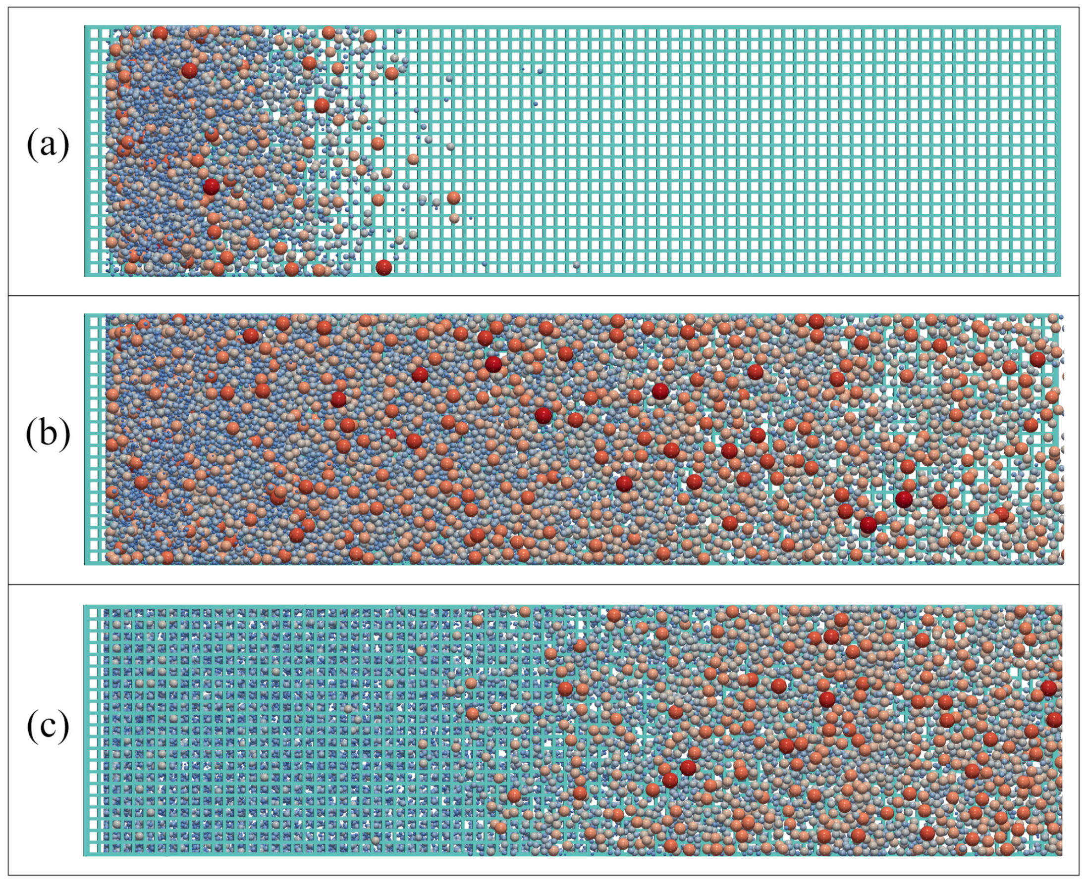
The entire process of screening was analyzed with a selected numerical experiment, the simulation condition was listed as follows: a = 1.8 mm , b / a = 0.5 , f = 25 Hz , α = 15 ° , θ = 40 ° and δ = 0 . As illustrated in Figure 7, the sieving process of the vibrating screen can be divided into three representative stages. In the beginning, the granular materials rapidly enter the screening area, a certain number of particles pass through the screen apertures directly while others rush toward the discharge end (Figure 7a). With the continuous feeding of raw materials, the screen cloth is covered with the raw materials for a period (Figure 7b). When the feeding process is finished, the number of particles remaining on the screen surface gradually dwindles, which means the sieving process is about to end (Figure 7c).
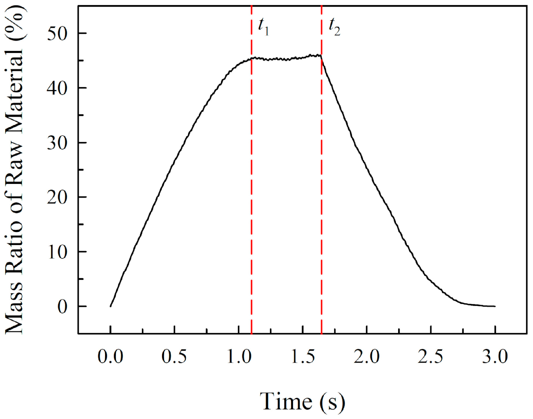
The time-dependent variation of the mass ratio between the raw material on the screen surface and the total feeding material is illustrated in Figure 8. As time goes by, the mass ratio increases dramatically at first, then fluctuates within a small range from the time t 1 to t 2 , and eventually exhibits a constant downtrend because the raw material stops being fed into the system. The period [ t 1 , t 2 ] signifies that the sieving process is in a stage of dynamic balance, which corresponds to Figure 7b. In the steady screening period, the mass of the raw material distributed on the screen surface is at its maximum, and the chance of collisions between the particles and the screen deck is also at a relative maximum value.
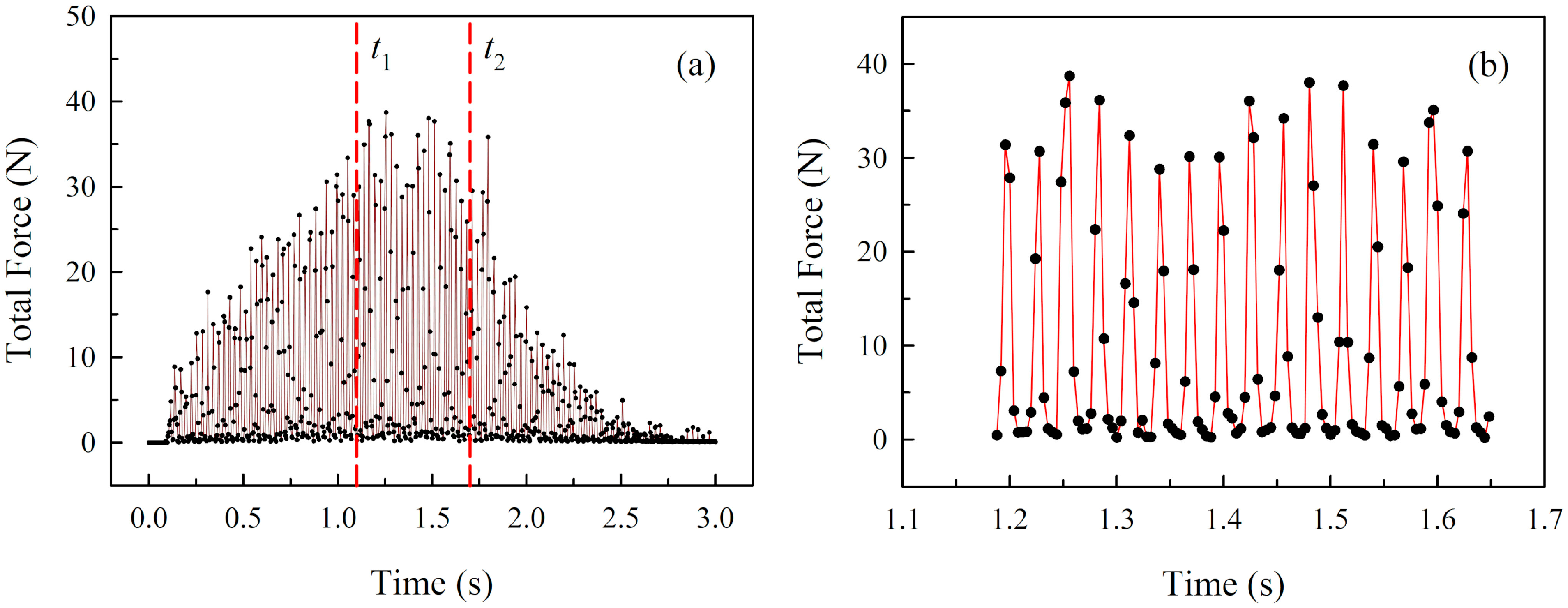
The time-dependent variations of the total impact force exerted by materials on the screen deck are illustrated in Figure 9. Apparently, the tendency of the total force during the entire sieving process shares a general similarity with that of the mass ratio, illustrated in Figure 8. Meanwhile, it can be found that the total force fluctuates within a certain range during the steady screening period, the impact force reaches the positive peak value in a period of elliptical vibration when the majority of particles are in contact with the screen deck (Figure 10a), and the impact force is at a negative peak value, which is basically equivalent to zero, since the particles have been ejected from the screen surface (Figure 10b).
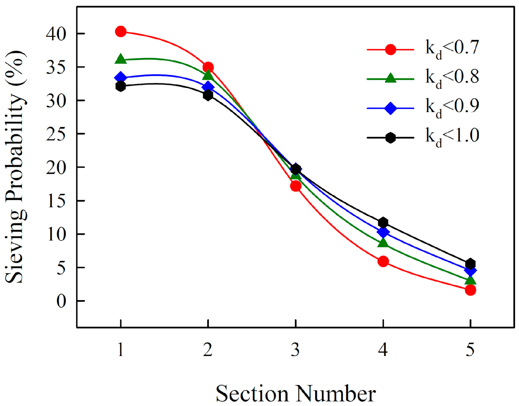
Moreover, the screening capacity of different areas on the screen deck was investigated, and the calculation results are illustrated in Figure 11, where the sieving probability p s i is expressed by
p s i = m i m s
where m i denotes the mass of the particles ( k d < k s ) which passed through the screen apertures in the i -th deck section and m s represents all the particles ( k d < k s ) in the fine product. Here, the target separation sizes 0.7, 0.8, 0.9 and 1.0 were adopted for investigation. Apparently, the sieving probabilities declined along with the movement direction of granular materials, which indicates that the passage behavior of particles is inclined to occur in the screening area closest to the input end. Additionally, the finer particles are more well-represented than the larger particles in terms of the screening capacity in the first two sections, but the trend is the opposite in the rest of the sections, where the larger particles occupy a dominant position during screening. Therefore, it can be concluded that the smaller particles possess a higher passage speed than the larger.
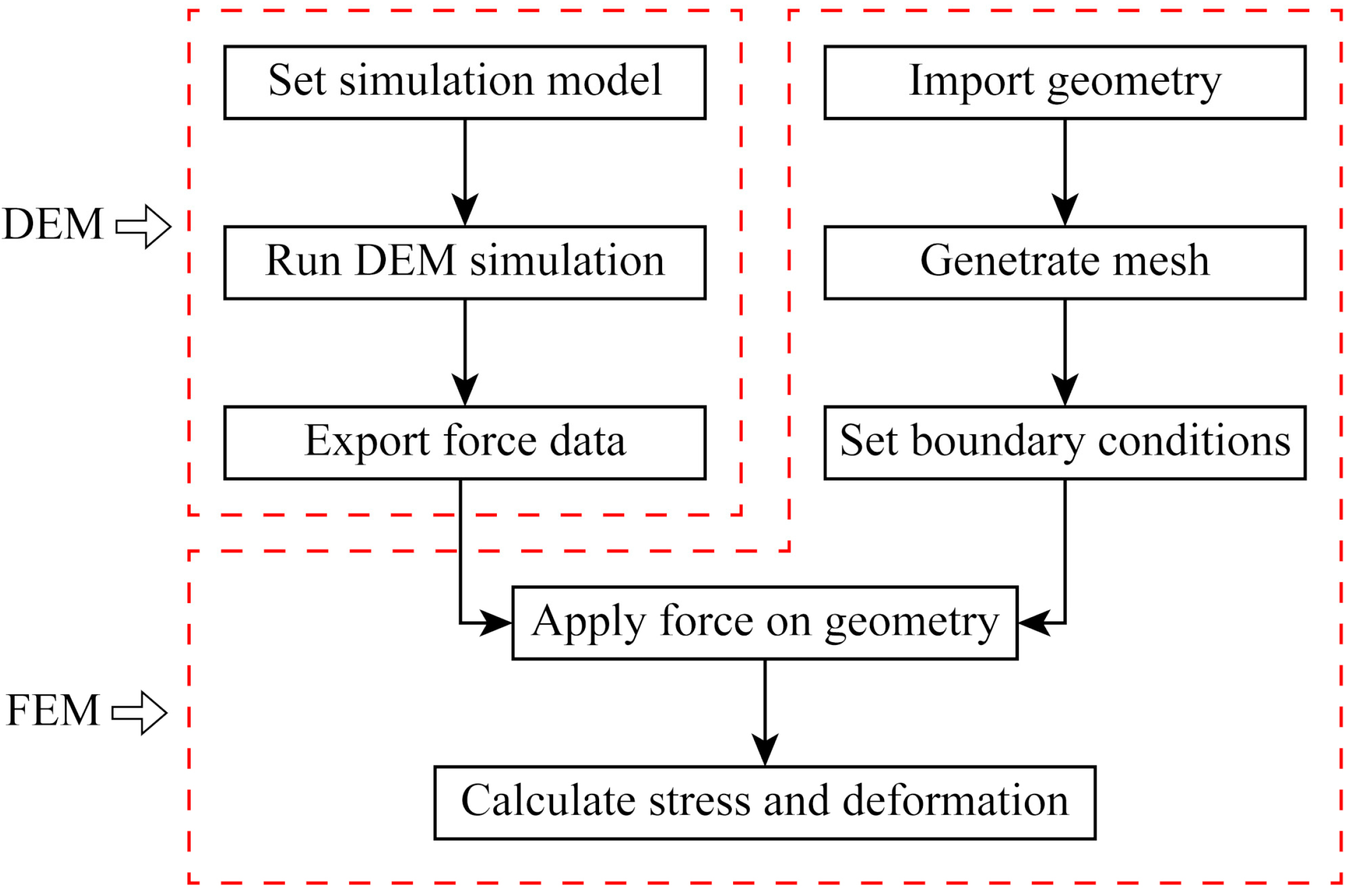
The DEM simulation proved to be capable of revealing the screening phenomenon of a vibrating screen, but the metal fatigue of the screen deck, one of the primary causes of worsened screening performance, remains poorly understood. However, it is impractical to simply conduct static analysis on screen deck by means of the finite element method (FEM), seeing that the position of the force application varies over time during the sieving process. In the present work, a DEM–FEM technique was introduced to solve this problem, and the coupled framework is illustrated in Figure 12.
When the DEM simulation of a sieving process was finished, the forces applied upon the screen surface by granular materials were exported by orienting and transposing them to the initial geometric position of the screen deck, then the prepared force data were loaded on the meshed simulation model for further analysis. As demonstrated above, raw materials experience repeated collisions and ejections on the screen surface over time, thus a specific moment cannot exactly reflect the actual impact suffered by the screen deck. In the present work, the average force data from a certain period were extracted for calculation of the equivalent stress and the total deformation of the screen deck. As illustrated in Figure 13, the distribution of stress and deformation was mainly affected by the movement of raw materials. The maximum impact is invariably concentrated on the input area of the granular materials before the materials have stopped being fed into the system, and then gradually spreads to the discharge end. Considering that the total force reaches the maximum value in the steady screening period (Figure 9b), in which the collision impact of particles on the screen deck is the strongest, the stress and deformation situations of this stage were investigated in this work.
According to Figure 14, the side edge of the material input field bears the highest stress, whereas the maximum deformation occurs in the middle of the material input field—thus, the maximum impact values of stress and deformation can be obtained. Consequently, it is of great importance to improve the assembly between the screen deck and the screen box in order to reduce the concentration of stress, and to add support beams in the material input area in order to ease the degree of deformation.

4.2. Univariate Analysis

In order to investigate the influencing mechanism of sieving parameters on the four previously presented performance indexes of the elliptical vibrating screen (the screening time of material processing, the screening efficiency of undersized materials, the maximum stress and maximum deformation suffered by screen deck) single-factor experiments were carried out for the univariate analysis of each parameter. The initial experimental conditions were listed as follows: a = 2.5 mm , b / a = 0.5 , f = 25 Hz , α = 15 ° and θ = 40 ° . The values of an individual parameter were adjustable, whereas those of other parameters remained constant in the following univariate experiments. Particularly, the vibration direction δ of the screen deck was analyzed with the other five parameters, because this factor only includes two properties, namely, the clockwise vibration mode and the anticlockwise vibration mode.
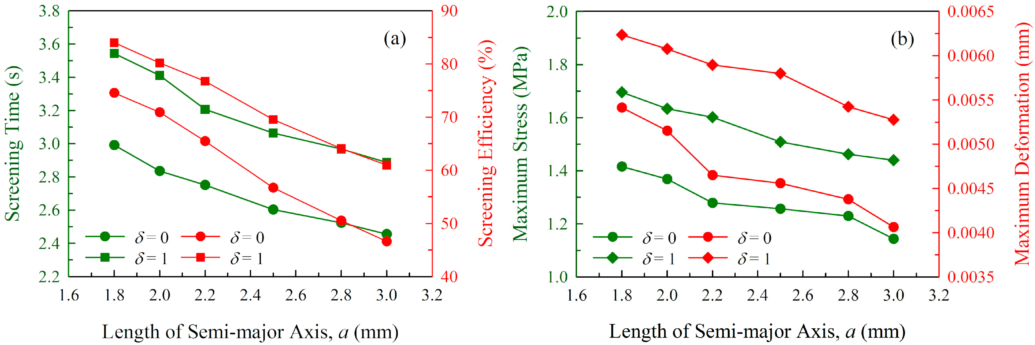
For the length of semi-major axis a , of which the value was adjusted to 1.8, 2, 2.2, 2.5, 2.8 and 3 mm in the univariate experiments, the influencing principles on performance indexes are illustrated in Figure 15. The screening time under clockwise vibration and anticlockwise vibration respectively decreased from 2.992 s and 3.544 s to 2.456 s and 2.888 s. The screening efficiency dropped from 74.590% to 46.629% in the clockwise mode and from 84.026% to 60.982% in the anticlockwise mode. The maximum stress and deformation in the clockwise mode respectively declined from 1.416 MPa and 0.00542 mm to 1.144 MPa and 0.00407 mm, and those under the anticlockwise mode respectively declined from 1.696 MPa and 0.00624 mm to 1.440 MPa and 0.00528 mm. Evidently, all the four performance indexes exhibited continuous downward trends with the increase of the semi-major axis from 1.8 to 3 mm, and each index under the anticlockwise vibration conditions was steadily larger than that under the clockwise vibration conditions.
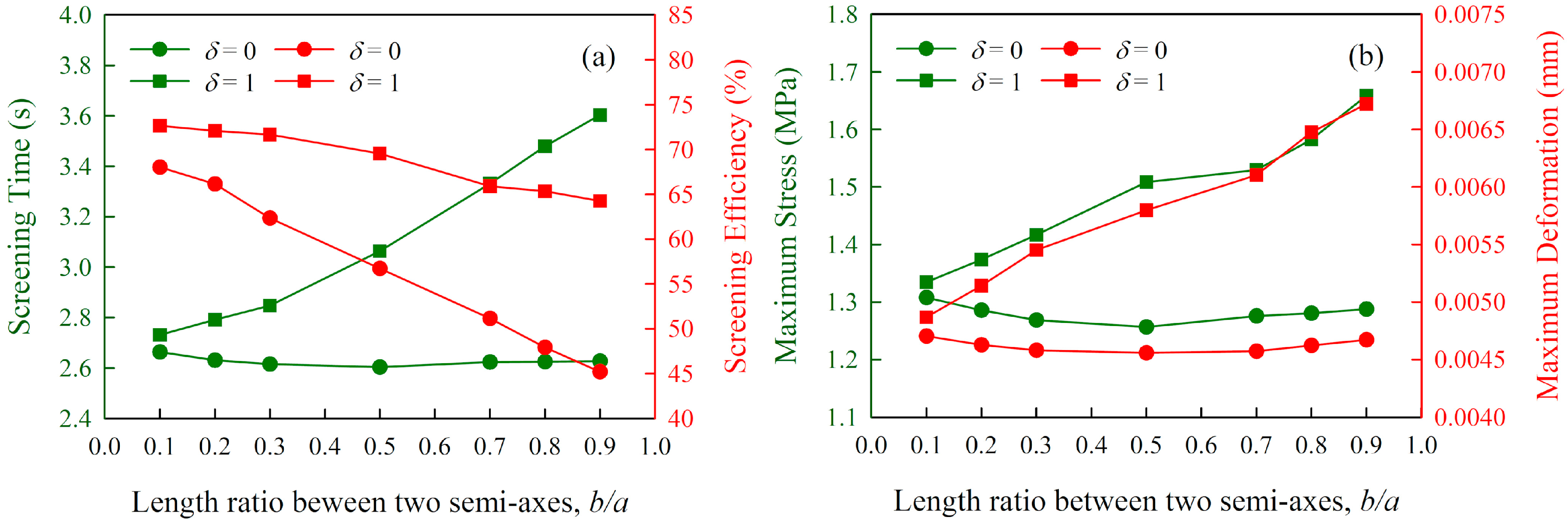
For the length ratio between two semi-axes b / a , of which the value was adjusted to 0.1, 0.2, 0.3, 0.5, 0.7, 0.8 and 0.9 in univariate experiments, the influences on performance indexes are illustrated in Figure 16. The screening time under clockwise vibration conditions showed a modest decline from 2.664 s to 2.604 s when b / a = 0.5 and then increased slightly to 2.628 s, whereas that under anticlockwise vibration conditions exhibited a substantial growth from 2.732 s to 3.604 s. The screening efficiency dropped from 68.043% to 45.221% with the clockwise vibration and from 72.661% to 64.259% with the anticlockwise vibration. The maximum stress and deformation in the clockwise mode decreased from 1.308 MPa and 0.00471 mm to 1.257 MPa and 0.00456 mm at b / a = 0.5 and then increased slightly to 1.288 MPa and 0.00467 mm, respectively, whereas those in the anticlockwise mode exhibit sharp increased from 1.335 MPa and 0.00487 mm to 1.659 MPa and 0.00672 mm, respectively. Evidently, there are significant differences in the screening results produced by the two vibration directions, and each performance index under the anticlockwise vibration conditions was constantly larger than that under the clockwise vibration conditions.
For the vibration frequency f , of which the value was adjusted to 18, 20, 22, 25, 28, 30 and 35 Hz in univariate experiments, the influences on performance indexes are illustrated in Figure 17. The screening time under the clockwise vibration and the anticlockwise vibration conditions decreased from 3.456 s and 3.544 s to 2.360 s and 2.820 s, respectively. The screening efficiency dropped from 82.496% to 37.173% in the clockwise mode and from 87.135% to 46.386% in the anticlockwise mode. The maximum stress and deformation in the clockwise mode respectively declined from 1.585 MPa and 0.00624 mm to 1.076 MPa and 0.00387 mm, and those in the anticlockwise mode respectively declined from 1.650 MPa and 0.00690 mm to 1.169 MPa and 0.00405 mm. Evidently, all four performance indexes exhibited constant downward trends with the increase of the vibration frequency from 18 to 35 Hz, and each index under the anticlockwise vibration conditions was steadily larger than that under the clockwise vibration conditions.
For the inclination angle α , of which the value was adjusted to 10, 12.5, 15, 17.5, 20, 22.5 and 25 degrees in univariate experiments, the influences on performance indexes are illustrated in Figure 18. The screening time under the clockwise vibration and the anticlockwise vibration mode decreased from 2.952 s and 4.044 s to 2.240 s and 2.324 s, respectively. The screening efficiency dropped from 67.808% to 36.924% in the clockwise mode and from 80.892% to 43.474% in the anticlockwise mode. The maximum stress and deformation in the clockwise mode respectively declined from 1.593 MPa and 0.00570 mm to 0.821 MPa and 0.00360 mm, and those in the anticlockwise mode respectively declined from 2.172 MPa and 0.00813 mm to 0.956 MPa and 0.00363 mm. Evidently, all four performance indexes exhibited constant downward trends with the increase in the inclination angle from 10 to 25 degrees, and each index under the anticlockwise vibration conditions was steadily larger than that under the clockwise vibration conditions.
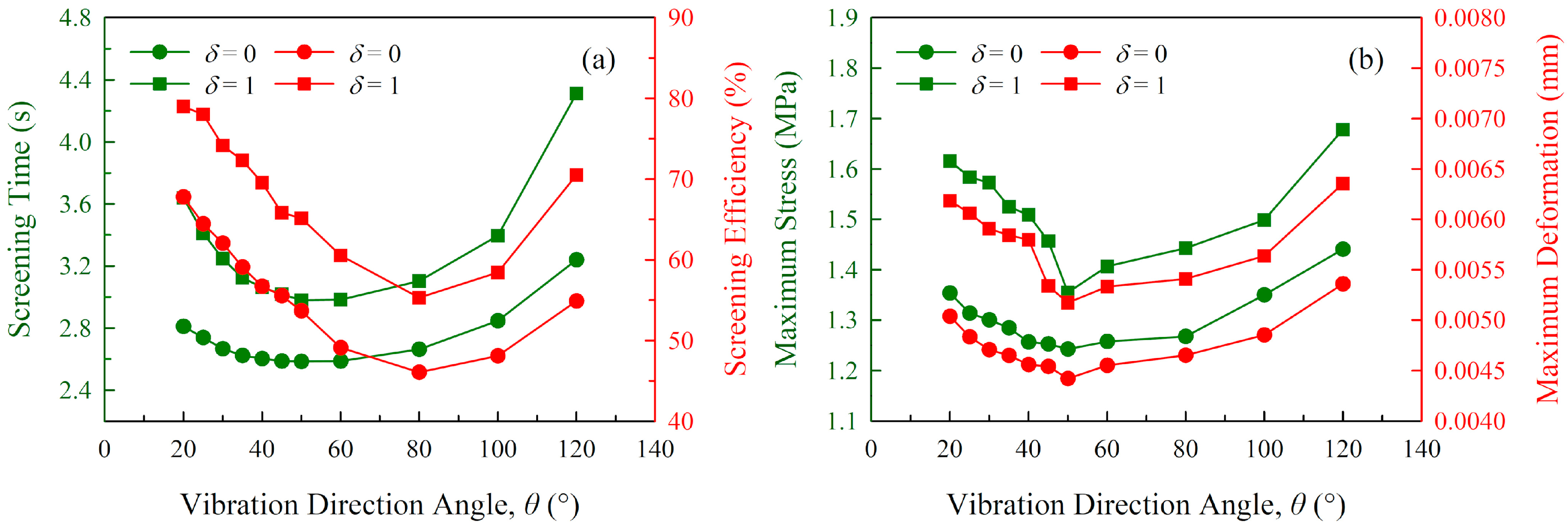
For the vibration direction angle θ , of which the value was adjusted to 20, 25, 30, 35, 40, 45, 50, 60, 80, 100 and 120 degrees in univariate experiments, the influences on performance indexes are illustrated in Figure 19. The screening time under clockwise vibration decreased modestly from 2.812 s to 2.588 s when θ = 50 ° and then constantly ascended to 3.24 s. Meanwhile, the screening time under anticlockwise vibration conditions exhibited a modest decline from 3.640 s to 2.980 s when θ = 50 ° and then increased drastically to 4.312 s. The screening efficiency under clockwise vibration conditions decreased from 67.812% to 46.077% when θ = 80 ° and then constantly rose to 54.898%. Meanwhile, the screening efficiency under anticlockwise vibration conditions decreased from 79.010% to 55.334% when θ = 80 ° and then constantly rose to 70.554%. The maximum stress and deformation in the clockwise mode decreased firstly from 1.354 MPa and 0.00504 mm to 1.243 MPa and 0.00442 mm when θ = 50 ° and then increased constantly to 1.441 MPa and 0.00536 mm, respectively, whereas those in the anticlockwise mode decreased firstly from 1.616 MPa and 0.00618 mm to 1.355 MPa and 0.00518 mm when θ = 50 ° , and then increased constantly to 1.678 MPa and 0.00636 mm, respectively. Obviously, there are negative peak values of the four performance indexes as the vibration direction angle increases from 20 to 120 degrees, whether the vibration direction angle is an acute angle or obtuse angle determines the influencing trend of screening efficiency, and θ = 50 ° is the separation point of the influencing trends for screening time and maximum impact of the screen deck. Meanwhile, each performance index under anticlockwise vibration conditions is constantly larger than that under clockwise vibration conditions.

4.3. Multivariate Analysis

Though the laws influencing the technical parameters affecting multiple screening indexes have been acquired by univariate analysis, the relative importance of these six parameters remains to be addressed. For this reason, the integrated effects of six operational parameters were further investigated based on the Taguchi orthogonal method. Considering that the vibration direction of the screen deck includes only two properties, a mixed-level orthogonal experiment was designed, with values listed in Table 3. Notably, the values 0 and 1 of the vibration direction δ denote the clockwise vibration and the anticlockwise vibration, respectively.
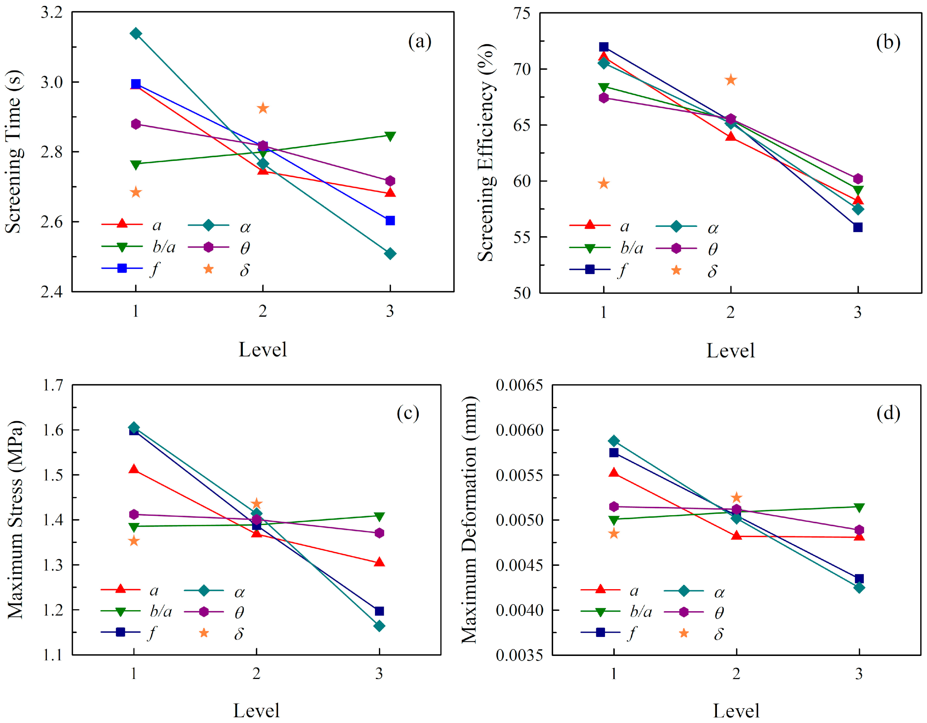
Eighteen groups of experiments were strictly implemented based on the orthogonal table. All the screening conditions and the corresponding results are summarized in Table 4, where t is the consuming time of screening process, η is the screening efficiency of undersized materials, σ max is the maximum stress and ε max is the maximum deformation. For the orthogonal experiment, range analysis is an effective method and is widely accepted for analyzing the orthogonal results. Different levels of a factor give rise to various results, and the range value of the factor is determined by the difference between the minimum result of a level and the maximum result of another level. The given factors can be ranked according to the magnitudes of range values, and a factor with a larger range value indicates that this factor has a greater effect on the result index. In light of its merits, range analysis was adopted in this work in order to evaluate the relative importance of sieving parameters on four performance indexes. The analysis results are illustrated in Figure 20.
Figure 20a displays the range analysis of screening time. The time investment of the screening process decreases with the increasing of the values of semi-major axis a , vibration frequency f , inclination angle α and vibration direction angle θ , while showing a modest growth with the increase of the length ratio between the two semi-axes b / a , and the anticlockwise mode spends more time for screening than the clockwise mode. According to the difference in the range values, the relative importance of the six influencing factors can be ranked from high to low as α > f > a > δ > θ > b / a . The inclination angle has the most significant influence on the screening time, whereas the length ratio between two semi-axes has the least.
Figure 20b exhibits the range analysis of screening efficiency. Evidently, the screening efficiency of undersized particles displays a downtrend with the increasing value of semi-major axis a , the length ratio between two semi-axes b / a , the vibration frequency f , the inclination angle α and the vibration direction angle θ , and the anticlockwise mode is likely to achieve higher screening efficiency than the clockwise mode. According to the difference in the range values, the relative importance of the six influencing factors can be ranked from high to low as f > α > a > δ > b / a > θ . The vibration frequency shows the greatest impact on screening efficiency, and the minimal influence is exerted by the vibration direction angle.
As for the maximum stress and deformation, of which the range analysis is respectively illustrated in Figure 20c,d, the results of both indexes share the similar feature that the impact applied on the screen deck decreases with the increasing value of the semi-major axis a , the vibration frequency f , the inclination angle α and the vibration direction angle θ , while increasing slightly with the growth of the length ratio between the two semi-axes b / a , and the anticlockwise mode leads to greater stress and deformation than the clockwise mode. According to the difference in the range values, the relative importance of the six influencing factors can be ranked from high to low as α > f > a > δ > θ > b / a , which is consistent with that of the screening time.
In general, the screening time has a negative correlation with the processing capacity, the screening efficiency directly reflects the quality of the screened product, and the stress concentration and plastic deformation are related to the metal fatigue of the screen deck. According to the optimization requirements of four performance indexes, the corresponding optimal schemes of sieving parameters were selected and are listed in Table 5. Notably, the parameter schemes of screening time, maximum stress and maximum deformation are exactly identical.

4.4. Relationship of Performance Indexes

In the bi-objective problem, the relationship between two variables can be measured by the Pearson correlation coefficient R , which is described by
R ( x , y ) = i = 1 n ( x i x ¯ ) ( y i y ¯ ) i = 1 n ( x i x ¯ ) 2 i = 1 n ( y i y ¯ ) 2
where x i and y i are the two variable values of the i -th sample, and x ¯ and y ¯ are the corresponding average values of a total of n groups of samples.
The relationships of the screening results obtained from the univariate experiments and multivariate experiments are illustrated in Figure 21, where the correlation coefficient R is calculated by Equation (20). According to the R values, it is clear that there is a strong positive correlation between each of the two performance indexes, which poses a tough challenge for the multi-index optimization of vibrating screens. Specifically, the screening time has the most minimal correlation with the screening efficiency (Figure 21a), and the maximum stress has the strongest correlation with the maximum deformation (Figure 21d), because the collision impact of the screen deck is only determined by the forces applied by granular materials. Meanwhile, the screening time has relatively strong correlations with the maximum stress and maximum deformation due to the Pearson R values both being larger than 0.9. Thus, it can be inferred that the processing performance of the vibrating screen has a great influence on the metal fatigue of the screen deck. A poor transportation capacity results in an excessive accumulation of particles on the material inputting field, the total impact force exerted by particles is then correspondingly increased, and thus eventually contributes to the large stress and deformation of the screen deck. Furthermore, the sample data are linearly fitted, and the regression functions are presented for a trade-off in terms of a performance optimization task with multiple indexes.

5. Conclusions

In this work, the screening processes of an elliptical vibrating screen under various parameter conditions were numerically investigated based on DEM, and the metal fatigue phenomena were further explored according to the DEM–FEM coupling approach. Six technical parameters of the screen deck—the length of the semi-major axis a , the length ratio between the two semi-axes b / a , the vibration frequency f , the inclination angle α , the vibration direction angle θ and the vibration direction δ —were employed as the target research variables in all simulation experiments, and the screening time, screening efficiency, maximum stress and maximum deformation served for the evaluation of sieving performance. The following conclusions can be drawn from the research contents:
(1)
DEM simulation is an effective approach in modeling the entire screening process related to massive granular materials and is conducive for lightening the data-collecting burden in experiments. Moreover, the stress and deformation distribution of a screen deck can be observed intuitively by coupling DEM with FEM. The analysis results indicate that the maximum stress mainly occurs in the side edges of the material input area, whereas the maximum deformation is concentrated in the middle of the material input area, which provides an optimization direction for reducing the fatigue and damage of screen decks.
(2)
The single-factor experiments and univariate analysis were conducted, and the results have clearly demonstrated the influence of six technical parameters. Meanwhile, Taguchi orthogonal experiments were designed in order to reveal the relative importance of sieving parameters and the optimal parameter scheme for each performance index. The results indicate that the importance of these parameters for screening efficiency is ranked as f > α > a > δ > b / a > θ , whereas that for screening time, maximum stress and maximum deformation are identically ranked as α > f > a > δ > θ > b / a . The optimal parameter scheme for maximizing the screening efficiency is: a = 2.2 mm , b / a = 0.25 , f = 20 Hz , α = 15 ° , θ = 30 ° and δ = 1 , whereas that for minimizing the screening time, maximum stress and maximum deformation is: a = 2.8 mm , b / a = 0.25 , f = 25 Hz , α = 20 ° , θ = 50 ° and δ = 0 .
(3)
The four performance indexes including the screening time, screening efficiency, maximum stress and maximum deformation are closely related to each other. More specifically, a poor processing capability directly promotes the retention time of particles on the screen surface; thus, when the materials receive more adequate passage opportunities, then the screening efficiency is enhanced. However, continuously feeding materials have no sufficient energy to eject and travel through the screen deck, but tend to accumulate in the material input field; thus, the time investment of the entire screening process and the impact force are correspondingly increased. The strong positive correlations among screening results are technically unavoidable due to the design of elliptical vibrating screens, therefore the relational functions were presented for a trade-off in terms of a multi-index optimization problem.

Author Contributions

Z.C. performed the numerical experiments, analyzed the modeling results and wrote the manuscript; X.T. proposed the research topic and supervised the entire project; Z.L. offered assistance and suggestions in the conduct of the experiments. All authors have read and agreed to the published version of the manuscript.

Funding

The research work is financially supported by National Natural Science Foundation of China (No. 51775113), Natural Science Foundation of Fujian Province (No. 2017J01675), 51st Scientific Research Fund Program of Fujian University of Technology (No. GY-Z160139), Key Research Platform of NC Equipment and Technology in Fujian Province (No. 2014H2002), and Subsidized Project for Postgraduates’ Innovative Fund in Scientific Research of Huaqiao University (No. 17013080007).

Acknowledgments

The authors would like to acknowledge the computer resources provided by Huaqiao University, and sincerely appreciate all the researchers involved for their meticulous efforts in this work.

Conflicts of Interest

The authors declare no conflict of interest.

References

  1. Jiang, H.; Zhao, Y.; Duan, C.; Zhang, C.; Diao, H.; Wang, Z.; Fan, X. Properties of technological factors on screening performance of coal in an equal-thickness screen with variable amplitude. Fuel 2017, 188, 511–521. [Google Scholar] [CrossRef]
  2. Liu, J.; Liu, H.; Yao, X.-L.; Liu, Y. Evaluating the sustainability impact of consolidation policy in China’s coal mining industry: A data envelopment analysis. J. Clean. Prod. 2016, 112, 2969–2976. [Google Scholar] [CrossRef]
  3. Dong, H.; Liu, C.; Zhao, Y.; Zhao, L. Influence of vibration mode on the screening process. Int. J. Min. Sci. Technol. 2013, 23, 95–98. [Google Scholar] [CrossRef]
  4. Cundall, P.A.; Strack, O.D.L. A discrete numerical model for granular assemblies. Géotechnique 1979, 29, 47–65. [Google Scholar] [CrossRef]
  5. Horabik, J.; Molenda, M. Parameters and contact models for DEM simulations of agricultural granular materials: A review. Biosyst. Eng. 2016, 147, 206–225. [Google Scholar] [CrossRef]
  6. Qiu, X. DEM Simulations in Mining and Mineral Processing. In Proceedings of the 7th International Conference on Discrete Element Methods; Springer: Singapore, 2017; pp. 37–43. [Google Scholar] [CrossRef]
  7. Deen, N.G.; Van Sint Annaland, M.; Van der Hoef, M.A.; Kuipers, J.A.M. Review of discrete particle modeling of fluidized beds. Chem. Eng. Sci. 2007, 62, 28–44. [Google Scholar] [CrossRef]
  8. Eppinger, T.; Seidler, K.; Kraume, M. DEM-CFD simulations of fixed bed reactors with small tube to particle diameter ratios. Chem. Eng. J. 2011, 166, 324–331. [Google Scholar] [CrossRef]
  9. Chu, K.W.; Wang, B.; Yu, A.B.; Vince, A. CFD-DEM modelling of multiphase flow in dense medium cyclones. Powder Technol. 2009, 193, 235–247. [Google Scholar] [CrossRef]
  10. Wang, G.; Tong, X. Screening efficiency and screen length of a linear vibrating screen using DEM 3D simulation. Min. Sci. Technol. 2011, 21, 451–455. [Google Scholar] [CrossRef]
  11. Cleary, P.W.; Sinnott, M.D.; Morrison, R.D. Separation performance of double deck banana screens—Part 1: Flow and separation for different accelerations. Miner. Eng. 2009, 22, 1218–1229. [Google Scholar] [CrossRef]
  12. Cleary, P.W.; Sinnott, M.D.; Morrison, R.D. Separation performance of double deck banana screens—Part 2: Quantitative predictions. Miner. Eng. 2009, 22, 1230–1244. [Google Scholar] [CrossRef]
  13. Jahani, M.; Farzanegan, A.; Noaparast, M. Investigation of screening performance of banana screens using LIGGGHTS DEM solver. Powder Technol. 2015, 283, 32–47. [Google Scholar] [CrossRef]
  14. Wang, Z.; Liu, C.; Wu, J.; Jiang, H.; Zhao, Y. Impact of screening coals on screen surface and multi-index optimization for coal cleaning production. J. Clean. Prod. 2018, 187, 562–575. [Google Scholar] [CrossRef]
  15. Jafari, A.; Saljooghi Nezhad, V. Employing DEM to study the impact of different parameters on the screening efficiency and mesh wear. Powder Technol. 2016, 297, 126–143. [Google Scholar] [CrossRef]
  16. Wang, X.; Li, Z.; Tong, X.; Ge, X. The influence of particle shape on screening: Case studies regarding DEM simulations. Eng. Comput. 2018, 35, 1512–1527. [Google Scholar] [CrossRef]
  17. Dong, K.; Esfandiary, A.H.; Yu, A.B. Discrete particle simulation of particle flow and separation on a vibrating screen: Effect of aperture shape. Powder Technol. 2017, 314, 195–202. [Google Scholar] [CrossRef]
  18. Zhao, L.; Zhao, Y.; Bao, C.; Hou, Q.; Yu, A. Optimisation of a circularly vibrating screen based on DEM simulation and Taguchi orthogonal experimental design. Powder Technol. 2017, 310, 307–317. [Google Scholar] [CrossRef]
  19. Li, Z.; Tong, X.; Zhou, B.; Wang, X. Modeling and parameter optimization for the design of vibrating screens. Miner. Eng. 2015, 83, 149–155. [Google Scholar] [CrossRef]
  20. Combarros, M.; Feise, H.J.; Zetzener, H.; Kwade, A. Segregation of particulate solids: Experiments and DEM simulations. Particuology 2014, 12, 25–32. [Google Scholar] [CrossRef]
  21. Delaney, G.W.; Cleary, P.W.; Hilden, M.; Morrison, R.D. Testing the validity of the spherical DEM model in simulating real granular screening processes. Chem. Eng. Sci. 2012, 68, 215–226. [Google Scholar] [CrossRef]
  22. Yin, Z.; Zhang, H.; Han, T. Simulation of particle flow on an elliptical vibrating screen using the discrete element method. Powder Technol. 2016, 302, 443–454. [Google Scholar] [CrossRef]
  23. Wen, B.; Zhang, H.; Liu, S.; He, Q.; Zhao, C. Theory and Techniques of Vibrating Machinery and Their Applications; Science Press: Bejing, China, 2010. [Google Scholar]
  24. Di Renzo, A.; Di Maio, F.P. Comparison of contact-force models for the simulation of collisions in DEM-based granular flow codes. Chem. Eng. Sci. 2004, 59, 525–541. [Google Scholar] [CrossRef]
  25. Chen, J.; Furuichi, M.; Nishiura, D. Discrete Element Simulation and Validation of a Mixing Process of Granular Materials. Materials 2020, 13, 1208. [Google Scholar] [CrossRef] [PubMed] [Green Version]
  26. Zhou, Y.C.; Wright, B.D.; Yang, R.Y.; Xu, B.H.; Yu, A.B. Rolling friction in the dynamic simulation of sandpile formation. Phys. A Stat. Mech. Appl. 1999, 269, 536–553. [Google Scholar] [CrossRef]
  27. Xiao, J.; Tong, X. Characteristics and efficiency of a new vibrating screen with a swing trace. Particuology 2013, 11, 601–606. [Google Scholar] [CrossRef]
Figure 1. Mechanical model of twin-shaft elliptical vibrating screen.
Processes 08 01151 g001
Figure 2. Schematic illustration of the computing method of any elliptical trace.
Processes 08 01151 g002
Figure 3. Kinetic analysis of a particle on the screen surface.
Processes 08 01151 g003
Figure 4. Hertz–Mindlin (no-slip) contact model.
Processes 08 01151 g004
Figure 5. A simplified geometric model of the vibrating screen (dimensions in mm).
Processes 08 01151 g005
Figure 6. Numerical simulation of the sieving process.
Processes 08 01151 g006
Figure 7. Sieving process of the vibrating screen: (a) the beginning stage; (b) the steady stage; (c) the finishing stage.
Processes 08 01151 g007
Figure 8. The mass ratio of raw materials on the screen surface versus time.
Processes 08 01151 g008
Figure 9. Time-dependent variations of total impact force during (a) the entire screening process and (b) the steady screening period.
Processes 08 01151 g009
Figure 10. Motion behavior of the granular materials in the steady screening period (the velocity directions of particles are represented by arrows): (a) the collision of particles; (b) the throwing of particles.
Processes 08 01151 g010
Figure 11. Sieving probabilities of the five sections.
Processes 08 01151 g011
Figure 12. Computational framework of the discrete element method–finite element method (DEM–FEM) coupling method.
Processes 08 01151 g012
Figure 13. Distribution of (a) the equivalent stress (MPa) and (b) the total deformation (mm) suffered by a screen deck during the sieving process.
Processes 08 01151 g013aProcesses 08 01151 g013b
Figure 14. Distribution of (a) the equivalent stress (MPa) and (b) the total deformation (mm) suffered by a screen deck in the steady screening period.
Processes 08 01151 g014
Figure 15. Experimental results pertaining to the length of the semi-major axis: (a) screening time and screening efficiency; (b) maximum stress and maximum deformation.
Processes 08 01151 g015
Figure 16. Experimental results pertaining to the length ratio between two semi-axes: (a) screening time and screening efficiency; (b) maximum stress and maximum deformation.
Processes 08 01151 g016
Figure 17. Experimental results pertaining to the vibration frequency: (a) screening time and screening efficiency; (b) maximum stress and maximum deformation.
Processes 08 01151 g017
Figure 18. Experimental results pertaining to the inclination angle: (a) screening time and screening efficiency; (b) maximum stress and maximum deformation.
Processes 08 01151 g018
Figure 19. Experimental results pertaining to the vibration direction angle: (a) screening time and screening efficiency; (b) maximum stress and maximum deformation.
Processes 08 01151 g019
Figure 20. Range analysis of the orthogonal experiment results: (a) screening time; (b) screening efficiency; (c) maximum stress; (d) maximum deformation.
Processes 08 01151 g020
Figure 21. Relationship of each of the two performance indexes: (a) screening time and screening efficiency; (b) screening time and maximum stress; (c) screening time and maximum deformation; (d) maximum stress and maximum deformation.
Processes 08 01151 g021
Table 1. Relative parameters of the simulation model.
Granular ParameterValue
Particle shapeSpherical
Particle size (mm)Mean: 2.5, 5 (Std Dev: 0.55)
Mass of all feeding particles (kg)2
Feeding rate (kg/s)1.2
Feeding height (mm)80
Geometric ParameterValue
Screen length (mm)600
Screen width (mm)150
Screen thickness (mm)2
Aperture size (mm)5 (square)
Perforating ratio (%)49.58
Vibration trajectoryElliptical
Length of semi-major axis, a ( m m ) 1.8–3
Length ratio of semi-minor axis, b / a 0.1–0.9
Vibration frequency, f ( H z ) 18–35
Inclination angle, α ( ° ) 10–25
Vibration direction angle, θ ( ° ) 20–120
Vibration direction, δ 0 (clockwise), 1 (anticlockwise)
Table 2. Material properties and collision coefficients.
Material PropertiesParticleWall
Poisson’s Ratio0.30.29
Shear Modulus (MPa)237992
Density (kg/m3)26787861
Collision PropertiesParticle–ParticleParticle–Wall
Coefficient of Restitution0.10.2
Coefficient of Static Friction0.5450.5
Coefficient of Rolling Friction0.010.01
Table 3. Factors and levels applied in the orthogonal experiments.
LevelFactor
a ( mm ) b / a f ( Hz ) α ( ° ) θ ( ° ) δ
12.20.252015300
22.50.522.517.5401
32.80.75252050
Table 4. Parameters and results of the orthogonal experiments.
No. a ( mm ) b / a f ( Hz ) α ( ° ) θ ( ° ) δ t ( s ) η ( % ) σ max ( MPa ) ε max ( mm )
12.20.2520153003.68489.9182.1050.00763
22.20.522.517.54002.73270.7571.4080.00506
32.20.7525205002.41644.0991.0540.00397
42.50.252017.54002.75272.1001.5620.00536
52.50.522.5205002.41649.7291.2660.00417
62.50.7525153002.67251.9901.2920.00456
72.80.2522.5155002.59659.6671.2090.00443
82.80.52517.53002.44451.4261.0990.00408
92.80.7520204002.44848.3311.1850.00439
102.20.2525204012.49664.5801.0760.00401
112.20.520155013.40484.0141.8530.00678
122.20.7522.517.53013.20073.0411.5710.00566
132.50.2522.5203012.56870.6021.1030.00421
142.50.525154013.09269.2101.4040.00509
152.50.752017.55012.96869.8091.5840.00555
162.80.252517.55012.50053.8991.2600.00441
172.80.520203012.71267.6851.3030.00476
182.80.7522.5154013.38468.3911.7700.00679
Table 5. Optimal parameter schemes for the performance indexes.
Performance Index a ( mm ) b / a f ( Hz ) α ( ° ) θ ( ° ) δ
Screening time2.80.252520500
Screening efficiency2.20.252015301
Maximum stress2.80.252520500
Maximum deformation2.80.252520500