1. Introduction
In China, the renewable energy represented by wind energy and photovoltaic is mainly distributed in the western region of China, while the load is mainly distributed in the southeast region. As the channel of energy transmission, LCC-HVDCs can significantly improve the utilization efficiency and consumption level of renewable energy. LCC-HVDCs has obvious advantages in operation stability, transmission capacity, and transmission distance, and thus it plays an important role in the selection of energy transmission mode. In East and Southeast China, power grid structure with multi-infeed LCC-HVDCs has been formed. Due to the heavy load density at the receiving end, the electrical distances between some DC dropping points are relatively close, and therefore the stability of the system has been greatly challenged.
Since thyristors does not have the ability of self-closed thyristors, which are used as the commutation elements, LCC-HVDCs often occur commutation failures due to alternating current (AC) system faults at the receiving end. In China, when three continuous commutation failures occur, protection of DC blocking will work. For example, in September 2015, commutation failures caused by AC line faults have occurred in East China power grid. The bipolar DC blocking of Jinsu HVDC network occurred, and the loss of power grid was 4.90 GW and the lowest frequency dropped to 49.85 Hz, which seriously worsened the safe operation level of the power grid.
When commutation failures occur, the var required by the converter station at the receiving end increases sharply, and the bus voltage at the inverter side decreases sharply at the same time, which leads to a significant reduction in the var support provided by capacitors in the system. The lack of var support will cause the expansion of the fault and the collapse of voltage in serious cases. Many measures have been taken to prevent commutation failures. The mechanism and influencing factors of commutation failure were analyzed in detail in the literature [
1,
2], and the main cause of commutation failure was summarized as a too small extinction angle under the operation state. In order to effectively improve the safe operation level, the power grid topology was improved to carry out the commutation failure predictive control [
3]; a new topology based on fixed capacitor and controllable capacitor commutation converter is proposed in [
4]; another widely used measure is adding dynamic var compensation equipment such as static var compensator (SVC), static var generator (SVG), and synchronous condensers at the receiving end [
5,
6], which can meet the var demand of converter station and improve the voltage recovery speed; some valuable studies calculate the voltage security region to guarantee the voltage stability margin under N-1 faults [
7,
8,
9] proposes a novel method to discriminate the critical commutation failure region of multi-infeed HVDCs system and the critical failure impedance boundaries on topology diagram can be therefore delimited by examining each bus in the AC system; some other valuable works in the literature [
10,
11] have studied the influence of electrical distance on the stability of LCC-HVDC. The above research greatly improves the stability and security of power system operation and the commutation failure is effectively restrained.
From the perspective of analytical tools, electromagnetic transient simulation (EGTS) [
12] and electromechanical transient simulation (EHTS) are most commonly used [
13]. The former is limited by the speed and scale of simulation, while the latter is seriously inaccurate due to the neglect of negative sequence components. When the fault type is asymmetric, it will produce great errors, resulting in more or less dynamic var reserve capacity obtained by simulation. When the value of dynamic var reserve is small, it is difficult to meet the var demand of the system under fault, resulting in the further expansion of the fault range; when the value of dynamic var reserve is too large, due to the high cost of dynamic var equipment, it will bring great economic waste. Intrinsically, obtaining dynamic var capacity of SCs in hybrid AC/DC networks is the computation of optimal power flow considering the constraints of transient stability (TSCOPF). In [
14], the trajectory sensitivity analysis is introduced to simplify and solve TSCOPF problems. As shown in
Table 1, many scholars have used different methods to solve it.
However, some challenges still remain.
(1) The differential algebraic equations describing the transient characteristics of hybrid AC/DC power grid have strong rigidity [
19], which is reflected by waveform in the simulation, resulting in dramatic changes and many burrs in the simulation waveform; when the step searching algorithm is used to determine the voltage security region boundary, a large error will occur.
(2) The large-scale TSCOPF problem has the characteristics of high nonlinearity and dimension, which also contains integer variables. How to efficiently solve large-scale TSCOPF problem is still a problem. The traditional method to solve TSCOPF problem is trajectory sensitivity analysis. However, due to the large scale of hybrid AC/DC power grid, it is difficult to realize the online solution considering that the dispatching time scale of China power grid is generally 5–15 min [
20,
21,
22].
(3) Since the DC subsystem has complex control links, the state equations describing these control links are often discontinuous, which will lead to state jump or non-convergence.
Therefore, in order to solve these challenges, a novel method to obtain dynamic var reserve in hybrid AC/DC networks is presented in this paper. The main contribution of this paper is listed as follows:
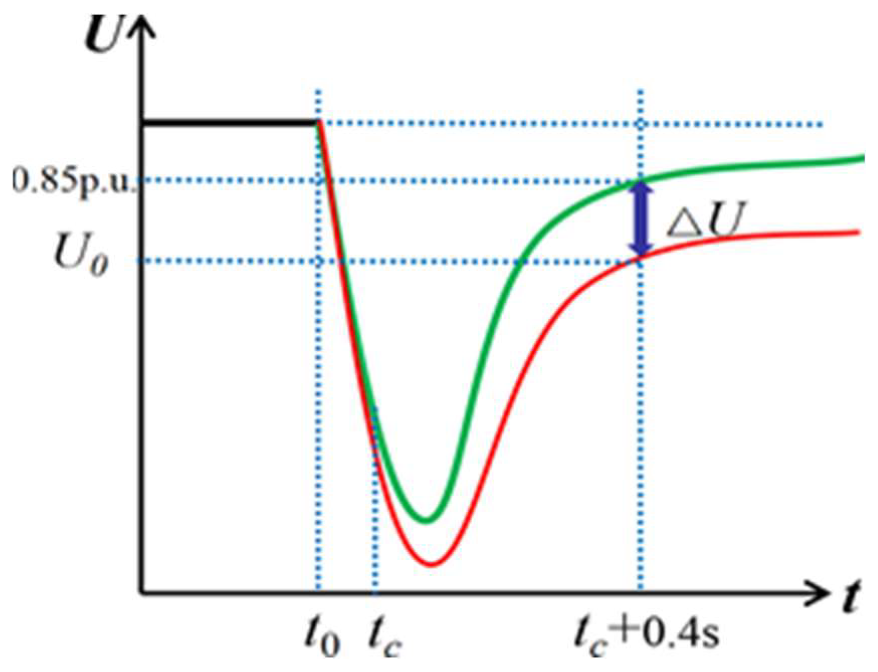
(1) The voltage sag area under fault is selected as the index to judge the fault severity, and the influence of different short circuit ratio and electrical distance of HVDC subsystem on voltage are analyzed clearly;
(2) With the help of data fitting method, the original voltage waveform with strong rigidity and many burrs is replaced by an approximately smooth voltage curve, and then the voltage stability boundary and dynamic var reserve capacity are determined by the step search algorithm. The proposed method is efficient and feasible, and is more convenient to be applied in engineering practice compared with traditional TSCOPF solving methods.
The structure of this paper is as follows: in
Section 2, a model with double-infeed LCC-HVDCs system is established and detailed parameters are introduced. Then in
Section 2.2, the mathematical model of double-infeed LCC-HVDCs is derived and the influence of DC subsystem on power system operation is analyzed. In
Section 3, the voltage sag area is introduced to quantify the severity of the faults. Next, the step searching algorithm and data fitting method are adopted to obtain dynamic var reserve capacity of SCs in
Section 3.2. In the case study, the accuracy and efficiency of the method proposed in this paper are verified. Finally,
Section 5 summarizes the full paper and gives the potential research directions in the future.
2. Double-Infeed LCC-HVDC System Model with Synchronous Condenser
2.1. The Introduction of the General Model
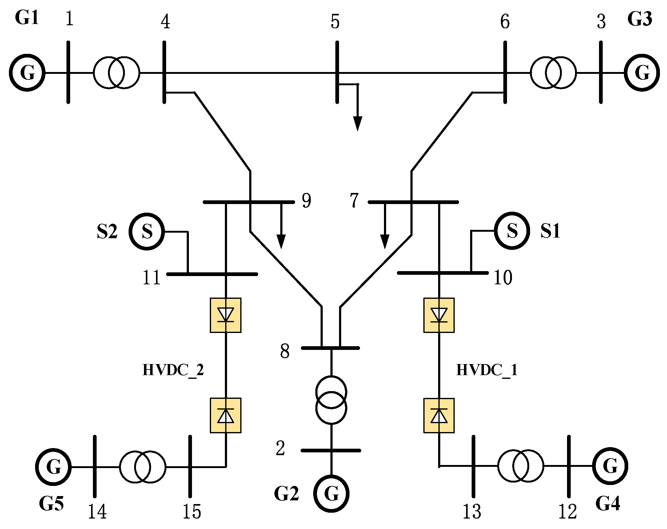
The general model of double-infeed HVDC system with SC is shown as
Figure 1.
The control modes of the first HVDC subsystem (HVDC1) and the second HVDC subsystem (HVDC2) are constant current control and minimum trigger angle control at the rectifier side and constant extinction angle control and constant current control at the inverter side.
It should be noted that the parameters of the model are the same with the CIGRE standard model and the capacity is 1000 MW. SC is connected to line-1. HVDC1 is connected to HVDC2 through line Z12, which is seen as the index reflecting the electrical distance. The relevant parameters of DC subsystem are set according to CIGRE model, which will not be described in detail here.
2.2. The Power Transmission Mathematical Model of the Double-Infeed LCC-HVDCs with Synchronous Condenser
For the independent HVDC
1 system, the mathematical model can be described as Equations (1)–(10).
Here, Ud1 and Id1 represent DC voltage and current; Pd1 and Qd1 represent active power and reactive power at the DC side, respectively. Pac1 and Qac1 represent active power and reactive power at AC side, respectively. Pc1 and Qc1 represent active power loss and var compensation capacity of filters and other var compensation device at the inverter side. XT1 represents leakage reactance of converter transformer and T1 represent transformer taps; Bc1 represents equivalent susceptance of filters and reactive power compensation device at the converter side; Z1 represents equivalent impedance of the system; U1∠δU1 and E1∠δE1 represent AC bus voltage and AC electromotive force, respectively. μ1 represents commutation overlap angle and γ1 represents the turn-off angle. Equations (1)–(10) are derived and mainly used to explain the impact of dynamic var equipment on the power flow in hybrid AC/DC power grid.
The power transmission equation of double-infeed LCC-HVDCs system with synchronous condenser needs to consider the reactive power transmission between synchronous condenser and HVDC
1, as well as the active power and reactive power transmission between HVDC
1 and HVDC
2. Therefore, the power equation of HVDC
1 Equations (9) and (10) is modified to Equations (11) and (12).
Here, P12 and Q12 are the active power and reactive power transmitted from HVDC1 to HVDC2 on the connecting line respectively. Qs represents reactive power transmitting from synchronous condenser to HVDC1.
If
Qs is within the capacity range of SC, the SC absorbs or produces var according to var demand; if
Qs is out of the capacity range of SC, then the SC is treated as a constant current source. Similarly, the power equations of HVDC
2 are shown as Equations (12)–(14). Here, Δ
P12 and Δ
Q12 represent active power/reactive power loss of tie lines. The expression of power transmission from HVDC
1 to HVDC
2 is shown as Equation (15).
The mathematical model of SCs can be expressed by Equations (16) and (17). Here, w represents rotor angular speed, Tj represents rotor inertia time constant, Pe represents electromagnetic power, D represents damping coefficient, Eq′ represents transient electromotive force, Td0′ represents direct axis transient open circuit time constant, Xd and Xq are synchronous reactances of direct axis and quadrature axis respectively, Xd′ represents direct axis transient reactance, Ra represents stator resistance, vd and vq represent direct and quadrature axis voltage components, respectively, id and iq represent direct axis and quadrature axis current components, respectively, and Efq represents excitation voltage.
It is widely accepted that SCs can provide fast var support when fault occurs in the hybrid AC/DC system. When the bus voltage of inverter converter station drops sharply, the var increment of the SCs is as follows:
Here, ΔU and UL represents the increment of bus voltage and bus voltage after short circuit fault, respectively; Δid and id0′ represent reactive current increment of synchronous condenser’s D-axis and reactive current of D-axis before fault, respectively.
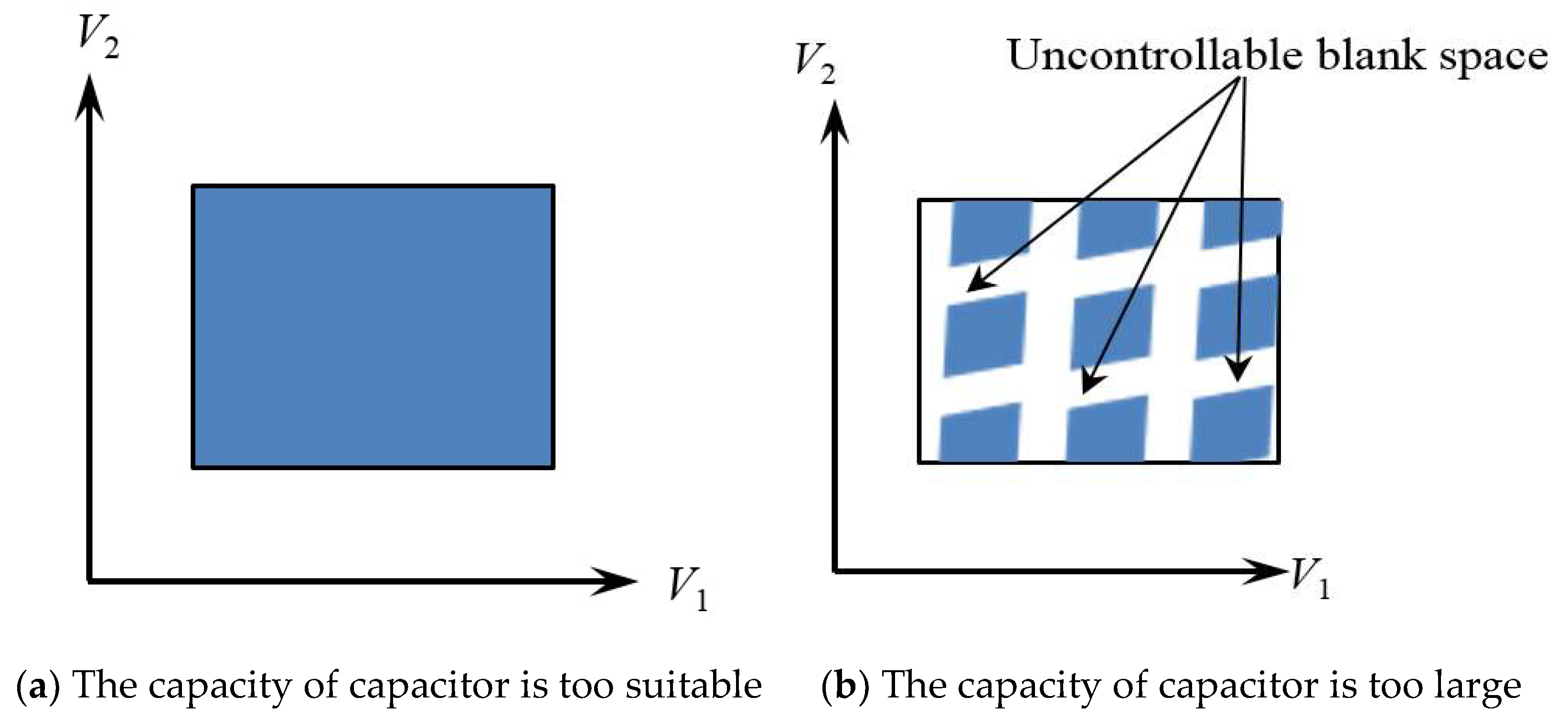
SC is essentially a no-load synchronous generator. Its function is to provide var for the system. The var can be regulated by adjusting the excitation current of SC. During over-excitation operation, the SC sends out inductive var and the system voltage increases. During under-excitation operation, the SC sends out capacitive var and the system voltage decreases. As shown in the
Figure 2 below, because SCs have the ability to continuously adjust var, it can be used to improve voltage recovery speed and prevent continuous commutation failure.
Although the multi-infeed LCC-HVDCs increase the capacity of the system at the receiving end, it also increases the spread path of voltage collapse under N-1 faults. SCs can quickly release a large amount of var in case of fault, providing emergent var and voltage support for the system. The spontaneous var response of SCs is an important means to suppress consecutive commutation failure.
5. Conclusions and Future Work
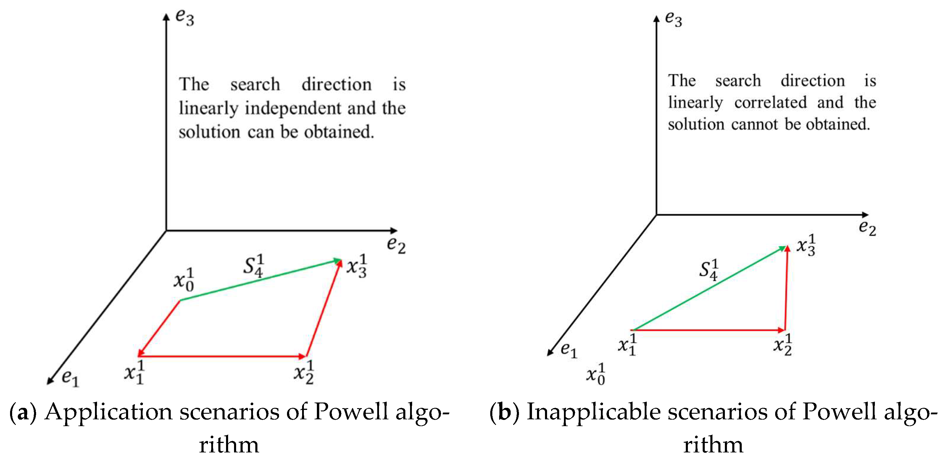
In order to overcome the shortcomings of high computational complexity and low solution accuracy of traditional dynamic var reserve evaluation methods, in this paper, a novel method to obtain dynamic var reserve capacity of SCs in multi-infeed LCC-HVDCs is proposed. This method does not need to solve the complex TSCOPF problem with the help of data fitting. Through data fitting method and improved Powell algorithm, the relationship between extinguishing angle of converter station and many other electrical parameters such as active power, reactive power and dynamic var equipment capacity can be described by high-order polynomials. The improved Powell algorithm can effectively overcome the limitations of the traditional least squares method and avoid falling into the local minimum value. Finally, the reserve capacity of dynamic var equipment is determined by step searching algorithm. In the part of case study, two test systems including double infeed LCC-HVDC system and the modified IEEE-9 system, are used to illustrate the effectiveness and feasibility of the proposed method. The following conclusions can be drawn from the simulation results:
1. After equipped with dynamic var equipment, the safe operation margin of hybrid AC/DC power grid is significantly improved. When faults occur in AC system, dynamic var equipment can quickly provide var and voltage support and prevent the further spread of fault influence.
2. It can be seen from the simulation results of voltage safety region that compared with traditional static var equipment, the dynamic var equipment can continuously adjust the voltage and enlarge the range of safe operation.
Although the research work of this paper mainly focuses on the dispatching operation of power system, the relevant methods and conclusions can be extended to system planning application. For power systems with multi-infeed LCC-HVDCs, how to equip appropriate dynamic var reserve for areas with serious voltage security and stability problems, including the capacity of configured equipment, the selection of installing address, the selection of equipment parameters and so on, can be deeply studied by using the conclusions given in this paper.
From the perspective of system control, this paper focuses on using the existing var and voltage regulation resources to make the system operate as safely as possible. However, with the expansion of the scale of China’s power grid and the increasingly complex operation mode, the participation and regulation of the power market will become an important means in the future. In the scenarios of large-scale new energy, it will become the trend of future research to study the pricing strategy of reactive auxiliary services based on effective dynamic var reserve evaluation and provide new var and voltage regulation means for these areas with insufficient dynamic var reserve. The pricing strategy of var auxiliary service can also be deeply studied based on the relevant theories of dynamic var reserve evaluation and optimization proposed in this paper.


