1. Introduction
In response to the medical demand for microscale equipment and the trend of miniaturization in various industries, the micromachining technology for each processing method is also increasing. This study targeted the promotion of wire electrochemical machining (WECM) performance on NiTi alloy by adding ultrasonic vibration to the electrolyte. Fine wires made of NiTi alloys have been widely used in medical applications. Based on its unique properties of superplasticity, shape memory and biocompatibility, NiTi alloy has been chosen as the material for various implant products such as mesh implants, guide line or stent. However, due to its high strength, high toughness, severe strain hardening and higher heat generation, NiTi alloy is difficult to be machined by conventional method [
1]. One of the major difficulties in the machining of NiTi is phase transformation. Heat generation during conventional machining methods affects the phase transformation of NiTi alloy [
2,
3]. Moreover, the chip during the machining process will retain NiTi characteristics. This causes poor chip breaking, formation of burrs, and high tool wear.
Since NiTi alloy is a thermally and externally stress-sensitive material, a conventional machining method might be difficult to meet the surface integrity requirements of medical products, including cleanliness, surface roughness, and burr-free edges. Thus, nonconventional machining methods such as electrical discharge machining (EDM), wire EDM, electrochemical machining (ECM), laser machining, and water jet machining are chosen for processing NiTi to address the problems of traditional machining methods. In this study, NiTi alloy was machined using the ECM technique, which avoided the drawbacks of traditional machining methods, including tool wear, mechanical stress microfissures induced by heat transfer, and surface oxidation.
As part of the development of nontraditional machining methods, electrochemical machining (ECM) has been widely used in the aerospace, vehicle, and medical equipment industries due to its unique processing characteristics, such as fast production speed, excellent surface quality, and lack of residual stress after machining. The machining method has plenty of unique advantages, such as high machining efficiency, lack of tool wear, absence of burrs, improved surface quality of the machined product, and the capability to machine complex shapes in electrically conductive materials regardless of their hardness. Since the method was introduced to the machining industry, it has been widely applied in modern aerospace and medical equipment mass-production processes.
In this research, the wire ECM method was utilized. According to previous research by other scholars, the wire ECM method reveals outstanding machining characteristics in micromachining, such as surface roughness, machining accuracy, and process stability. In 2008, Shin, H. et al. analyzed and studied the side gap of wire electrochemical micromachining. The researchers controlled the size of the generated bubbles by adjusting the pulse width so that the bubbles were removed from the machining gap before they accumulated [
4]. In 2012, Qu, N. et al. proposed the use of axial jet wire electrochemical machining of titanium alloy. The results showed that the small-pore-size nozzle could obtain a higher electrolyte flow rate, and that the electrolyte renewal rate and product elimination could be promoted [
5]. Liu, Z. et al. proposed the study of tungsten microelectrode fabrication by wire electrochemical machining, resulting in a tungsten microelectrode with a thickness of 21 µm and a width of 224 µm successfully fabricated under the preferred parameter setting [
6]. In 2014, Volgin, V. et al. proposed the modeling of the wire electrochemical machining mechanism to explore the influence of the machining path on the target geometry. Two basic graphs were proposed as examples, and different profile and path contour changes under the path planning were proposed, and suggestions for processing path planning were provided [
7]. In 2014, Zeng, Y. et al. proposed the study of a continuous wire electrochemical machining method. The results showed that the machining accuracy and stability improved with an increasing wire traveling speed [
8]. In 2013, Koyano, T. et al. succeeded in fabricating microblind holes on titanium alloys using ultrashort-pulse electrochemical machining, and achieved a very small hole expansion of 1 μm [
9]. In 2016, Fang, X. et al. successfully completed complex-shape microgroove machining on stainless steel using ultrashort-pulse wire electrochemical machining with a programmable moving platform [
10]. In 2014, Zeng, Y. et al. proposed the study of stray-current attack in reciprocated traveling wire electrochemical machining, and successfully performed a high-quality cut into 20 mm-thick stainless steel [
11]. In 2016, Fang, X. et al. proposed a multiple wire electrochemical micromachining (MWECMM) method, and the principle of the process was analyzed and verified through experiments [
12]. In 2016, Xu, K. et al. modified the surface characteristics of a wire cathode by using a travelling wire in wire electrochemical micromachining. The effects of wire cathode surface hydrophilia during the machining process was discussed. Finally, the accuracy of the microstructure fabrication was promoted, and higher feed rates could be achieved [
13].
For the NiTi alloy ECM process, several scholars have performed research in the past few years. In 2007, Ma, X. et al. proposed a confine-etchant-layer technique to manufacture microstructures on a NiTi alloy surface. The results showed a clear microscale 3D pattern on the workpiece surface [
14]. In 2009, Lee, E. et al. proposed the investigation of microgroove machining on NiTi shape memory alloy by short-pulse ECM. Various machining factors for NiTi alloy were evaluated in the study, such as different types of power sources and machining time [
15]. The authors also performed another study to evaluate the machinability of NiTi alloy with an electrochemical polishing method. Various machining characteristics were compared, and the surface roughness was promoted eventually by using an acid electrolyte [
16]. For micro-ECM processing of NiTi alloy, Ao, S. et al. proposed a microscale electrochemical milling method with an electrolyte containing ethanol. With the addition of ethanol, TiCl
4 on the workpiece was dissolved and the formation of oxide films was reduced, and finally the machining accuracy and surface quality was improved [
17].
In this study, wire electrochemical micromachining was used for microgroove machining of nickel–titanium alloy, and a tungsten wire with a diameter of 0.03 mm was used as an electrode. With the aid of ultrasonic vibration, the target was to improve the machining accuracy and machining speed. Eventually, the results are expected to be practically applied to mass production of microscale vessel stents, such as brain stents, in the near future.
3. Results and Discussion
3.1. Effect of Electrolyte on Slot Width
The electrolyte is one of the most important parameters in ECM process. The characteristics of different electrolytes or different electrolytic parameter setups can majorly effect the electrochemical dissolution behavior. Thus, it was crucial to study the machining condition under various electrolyte setups. In this experiment, an electrolyte mixture of sodium nitrate and sodium chloride was used, and the process was studied for the influence of processing characteristics of different concentrations. The experimental parameters were set to electrolyte concentrations of 0.5, 1.0, 1.5, 2.0, and 2.5 wt. %, and these were processed under the same processing conditions to compare the variation of the processed microgroove width and geometric shape.
The experimental results showed that as the electrolyte concentration increased, the groove width of the processing tank also increased. However, when the electrolyte concentration was 0.5 wt %, the removal of the processing groove was uneven, as shown in
Figure 5a. It was speculated that under this processing parameter, the polarization phenomenon of the interelectrode electrolyte was gradually amplified as the electrolyte concentration gradually decreased, and reached a stable processing critical concentration at 1.0 wt %, as shown in
Figure 6.
3.2. Effects of Working Voltage on Slot Width
Under ideal conditions, the electrochemical machining system can be regarded as a simple RC circuit. When the external environment and experimental setting parameters are fixed, the resistance between the two poles is fixed. Therefore, when the voltage rises, the corresponding current will increase base on Ohm’s law. According to Faraday’s law, the mass of the anode dissolution is proportional to the processing current; that is, the higher the processing voltage, the higher the material removal rate.
The voltage test was carried out with solution concentration of 1 wt % electrolyte of (NaNO
3:NaCl) 7:3, a pulse period of 1 μs, a pulse width of 250 ns, an electrode feed rate of 0.6 μm/s, and voltages of 18 V to 24 V. The experimental results showed that the machining groove width did not change much when the machining voltage was set from 20 V to 24 V. However, when the voltage continued to drop to 18 V, the downward trend occurred. It was speculated that under higher voltages (20 V to 24 V), the current drawn also was relatively increased, so the stray current effect was more severe, and was unable to concentrate in the processing area, so eventually the groove width did not increase with the increasing voltage, as shown in
Figure 7 and
Figure 8. However, as the voltage dropped to 18 V, the characteristics of the nonlinear electrolyte were relatively more obvious due to the smaller current drawn, and the processing amount of the region where the current density was insufficient was reduced, and finally the processing groove width was lowered.
3.3. Effect of Pulse Width on Slot Width
Due to the pulse power supply of the experiment, aside from the working voltage, the pulse width also was proportional to the amount of input energy. In order to investigate the effective difference between the two power supply parameters, a pulse width experiment was used in the research. In this study, the process used a very short pulse on-time with a long pulse off-time setting to improve the electrolyte renewal condition in the machining gap, which finally reduced the stray current and improve the machining accuracy. In this study, a fixed-pulse period of 1 MHz was used to investigate the effect of different pulse widths on processing characteristics. In the fixed-pulse period, the pulse width determined the amount of input energy for which the pulse width could be expected to be proportional to the microgroove width. However, in order to compare the working voltage differences under the same energy parameters, this experiment was tested under two extreme working voltages. Different pulse widths of 150, 200, 250, and 300 ns were discussed to investigate the relationship between the groove width and the pulse width.
The experimental results showed that the relationship between the pulse width and the slot width was proportional, as expected. However, when the pulse width was gradually reduced to 200 ns, the processing voltage of 18 V could no longer draw enough current to achieve material removal, as shown in
Figure 9a, so the minimum processing slot width was under the parameters of a processing voltage of 24 V and a pulse width of 200 ns, as shown in
Figure 10.
3.4. Effect of Feeding Rate on Slot Width
In an ideal electrochemical process, the feed rate of the electrode is set to be the same as the rate of dissolution of the anode, to achieve the highest processing efficiency. If the feed rate is too slow, the amount of reaming in the processing area will increase. If the feed rate is too fast, the inter-electrode gap will become shorter and shorter, and eventually make contact with the workpiece. The experiment was processed at four feed rates of 0.6, 1.0, 1.5, and 2.0 μm/s, of which 0.6 μm/s was the lowest moving speed of the Mitsubishi EA8 EDM machine. In order to reach the optimal feed rate, ultrasonic vibration was added to the experiment. The experimental results showed that the processing groove width gradually narrowed with the increase of the feed rate, and reached the minimum width when the feed rate was 2.0 μm/s. In the meantime, the processing groove wall began to show an uneven edge, as shown in
Figure 11d. It was presumed that a few short circuits were generated at this feed rate. At a feed rate exceeding the dissolution rate of the anode, the process still was able to complete the machining due to the 0.025 mm initial gap set before processing, which buffered the speed difference between the feed rate and the removal rate. The experiment results measurements are shown in
Figure 12.
3.5. Effects of Ultrasonic Aiding on the Slot Width
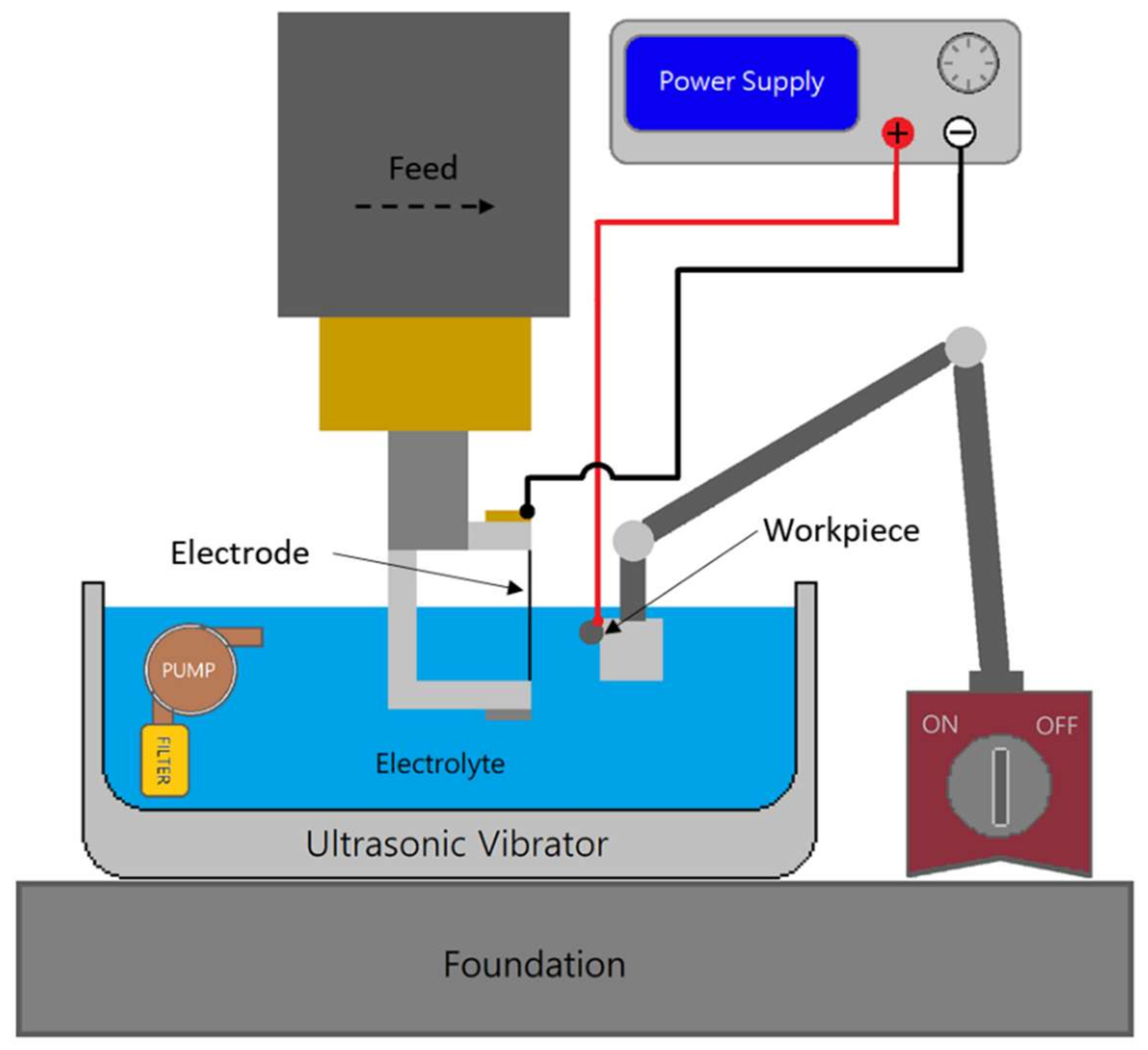
In the micro-electrochemical machining process, the processing efficiency has a close relationship with the renewal rate of the electrolyte. Due to the scale of the micromachining, it is often difficult for the electrolyte to flow through the gap, eventually causing electrolyte polarization or even a short circuit. Therefore, this study used ultrasonic assistance to promote the renewal of the electrolyte between the electrodes, and the machining process could be accelerated. The aiding mechanism is shown in
Figure 13.
In this experiment, the parameters of the concentration test were used, and the influence of the ultrasonic assistance on the groove-width machining was examined. The experimental results showed that with the aid of ultrasonic vibration, the processing results of each concentration were significantly improved, as shown in
Figure 14 and
Figure 15. Without ultrasonic assistance, the machining results were inefficient and uneven, but with the ultrasonic vibration, the vibration wave accelerated the renewal rate of the gap electrolyte and thus promoted the efficiency. After a series of experiments, an optimal parameter was obtained. Under the optimal parameter setup, a fine 54.2 µm-wide groove was fabricated on a Nitinol wire, as shown in
Figure 16.
3.6. Workpiece Observation and Analysis
NiTi alloy is a composite of nickel and titanium, and the composition of these two elements creates the special mechanical characteristic of the alloy, including shape memory, superelasticity, sensitive temperature deformation (dental), corrosion resistance, shock-absorbing ability, and most importantly, an outstanding biocompatibility. When the material is introduced to the human body, it is crucial that the material does not damage the body, and the material itself also cannot be damaged by the body’s environment. Thus, NiTi alloy was chosen to be the ideal material for implanting parts, and it was necessary to study the surface morphology and content of the workpiece after machining due to the terminal medical application of the technology.
Figure 17a shows the surface morphology and the content element of the machined surface. A minimum groove width of 54.2 µm was machined under a working voltage of 24 V, a pulse period of 1 µs, a pulse of width 200 ns, a feeding rate of 1.5 µm/s, an electrolyte concentration of 1 wt %, and ultrasonic vibration assistance on. Based on the sintering fabrication process of nickel–titanium alloy, the surface texture was shaped into a micro-golf-ball surface after machining, and the pot was considered as the material powder grain of the NiTi alloy. According to the results of the analysis, the content of the machined workpiece surface was identical to the original NiTi alloy content, and the element mapping results showed the same consequence, as shown in
Figure 17b and
Figure 18. To ensure the performance of the presented method, a continuous machining test was carried out, as shown in
Figure 19. The results showed consistent slot widths of 57 µm ± 5 µm, as shown in
Table 3.


