1. Introduction
In a situation where it is difficult to improve the surface roughness by traditional finishing methods due to the varying shapes of workpieces, magnetic abrasive finishing (MAF) has the potential to perform well in the machining processes. MAF is an advanced machining technique that drives a magnetic abrasive, for polishing or grinding the workpiece surface, through a magnetic field. The machining process first places a hard abrasive and a magnetic abrasive in the processing area. When the magnetic abrasive is attracted to a magnetic field, the abrasive particles will orient along the magnetic lines of force to form a magnetic brush [
1,
2]. When these magnetic brushes move relative to the workpiece surface, the micro-protruding edges on the workpiece surface can be removed by the grinding action of abrasive particles. In addition, the magnetic brush formed by these abrasive particles is able to flexibly adapt to various types of workpiece surfaces. There are four main advantages of MAF. First, MAF can be used not only for grinding planes but also for grinding cylinders, inner holes, tubes, or complex curved surfaces [
3,
4]. Second, in addition to the rotating motion, the MAF provides a reciprocating motion that can generate staggering movements to improve polishing performance [
5]. Third, the flexible abrasive will keep rolling and moving during the process of MAF, so that the abrasive particles can constantly grind the workpiece surface with sharp cutting edges which become increasingly sharpened, known as the self-sharpening phenomenon, which greatly improves the precision and efficiency of finishing [
6,
7]. Finally, MAF can grind both ferromagnetic and non-ferromagnetic materials.
The type of abrasive is one of the important factors affecting the efficiency of MAF [
8]. The production methods of magnetic abrasives can be divided into two categories: unbonded magnetic abrasives (UMAs) and bonded magnetic abrasives (BMAs) [
3,
6,
9]. The UMA method uses a mixture of magnetic particles and hard abrasive particles. By using the magnetic field and the processing pressure, the UMA will be tightly attached to the workpiece surface for grinding. However, the hard abrasive particles in the UMA are easily jettisoned from the processing area during machining due to their non-magnetic properties. This phenomenon will reduce the stability of the grinding process and stain the machining equipment. The BMA method can counter the disadvantages of the UMA approach mentioned above. The BMA approach uses chemical or mixing methods to sinter magnetic particles and hard abrasive particles together. Therefore, the non-magnetic hard abrasive particles will not be ejected from the processing area with rotation of the machine. However, the BMA has some major disadvantages, which include complex manufacturing processes, high manufacturing costs, and inability to produce finer abrasive particles.
Recently, a magnetic gel abrasive finishing (MGAF) method has been proposed to address the shortcomings of MAF; after polishing using the MGAF method, surface characteristics were significantly improved [
10,
11,
12]. Wang et al. [
10] used silicone gel as a carrier to mix steel grits and SiC in the production of a magnetic gel abrasive for polishing cylindrical workpieces. The experimental results showed that surface roughness with MGAF could reduce from 0.677 to 0.038
mRa within 30 min. The polishing efficiency of MGAF was triple that of applying MAF over the same time period [
6]. The magnetic gel abrasive restrains steel grits and SiC particles inside the silicone gel, such that the SiC particles do not scatter during the polishing process. In addition to improving the stability of the magnetic polishing, the MGAF method does not stain the machining equipment. Furthermore, the MGAF method has been proven to generate the advantages of low grinding pressure, non-deformation of the workpiece, and non-deterioration or micro-cracking of the polished surface. Therefore, the surface roughness of the workpiece can be effectively improved by using the MGAF method [
13,
14]. Some extensive research has sought to solve the problems associated with the multi-directional machining of workpieces [
15,
16,
17]. Such research has involved the design of complex motion mechanisms to achieve machining goals and has obtained good results. However, these particular mechanisms take up more space and entail high development and production costs.
In order to replace the complex reciprocating mechanism, accomplish size reduction, and reduce development and production costs, the current study developed a rotating cylinder-based magnetic finishing setup to allow the gel abrasive and workpieces to tumble and rotate together during the polishing process. Furthermore, three methods of servo motor control, including a unidirectional trapezoidal wave method, a bidirectional sine wave method, and a bidirectional trapezoidal wave method, were adopted in this study to drive the cylinder to create irregular and complex motions, so that the gel abrasive can perform polishing well. In addition, this study also involved comparison of polishing characteristics using several SiC particle and steel grit sizes to obtain the optimal polishing solutions. In general, the rotating cylinder-based magnetic gel abrasive finishing setup, proposed in this paper, not only improved polishing performance but also achieved improved quality of the surface of the workpiece.
2. Materials and Methods
2.1. Gel Abrasive in Internal Magnetic Finishing
MAF uses the magnetic brush formed on the inner wall of the tube to rub against the workpiece, which will remove micro-protrusions on the surface of the workpiece. The magnetic brush is constituted with the silicon carbide (SiC) as the abrasive, the steel grit controlled by the magnetic field, and the slime gel or guar gum, to link all materials in the gel abrasive. The gel abrasive spreads to the inner tube. The servo motor is controlled by the magnetic field of the abrasive, which controls the specimen’s finishing in a clockwise and counterclockwise rotation.
The rotating cylinder-based magnetic gel abrasive finishing process incorporates a tube placed in the rotary drum, with powerful magnets placed between the drum and the tube, to create a stirring system, with the workpiece placed inside the tube. The gel abrasives consist of slime gel and steel grit (magnetic particles) and are used to fill the remaining space in the tube. The gel will affect the efficiency and the precision of MAF. The finishing is controlled by the steel grit in the gel through the magnetic field steered by the servo motor. In this study, a multi-directional finishing path is generated during the changing motor process. Concurrently, the colloidal magnetic abrasive continues to roll and shift during processing. This gel abrasive is self-sharpening because the old abrasive is squeezed to the back, and the new abrasive is replenished.
2.2. The Magnetic Gel Abrasive Finishing with Servo Controller
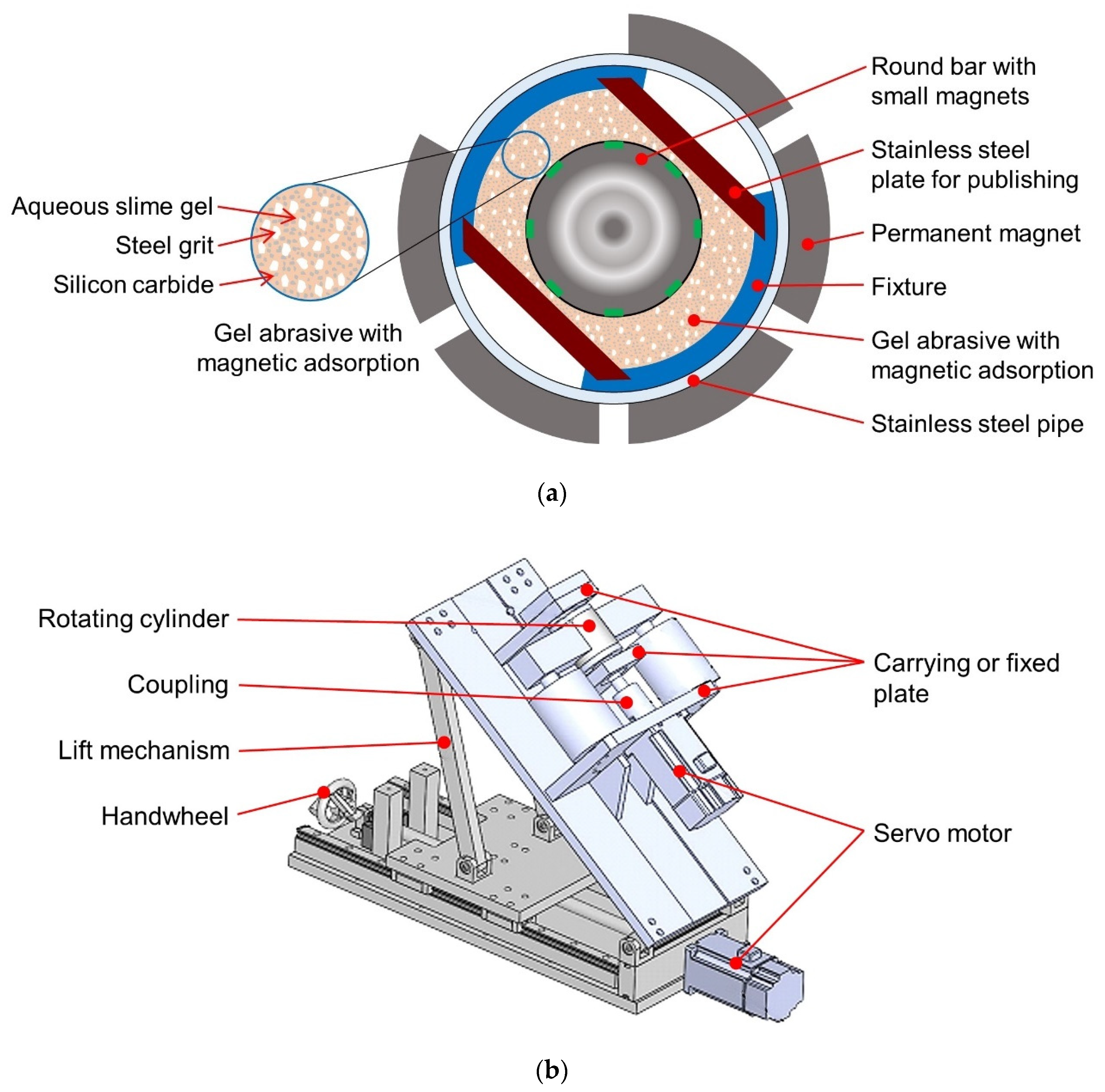
The rotating cylinder-based magnetic gel abrasive finishing with servo controller is shown in
Figure 1a,b. The MAF process abrades the particles on the surface, removes irregular peaks, and polishes the surface. The structure of the MAF mechanism is a workpiece-like stainless-steel plate and round bar, with small magnets fixed on the inner surface of a stainless-steel pipe. The remaining space of the pipe is filled with gel abrasive. When changing the rotating motion mode of the stainless-steel pipe via the servo controller, the MAF mechanism finishes the workpiece. The rotating cylinder, the fixture, and other structures of finishing were designed with computer-aided design software and solid models and were manufactured by CNC wire-cut electrical discharge machining. Subsequently, the different rotational motions of the pipe were developed and programmed in a visual studio.
2.3. Experimental Material and Setup
Three different material workpieces, including aluminum (Al), medium carbon steel plate, and stainless-steel plate were used in the MAF mechanism. In the beginning, the geometry size of these three workpieces was normalized to measure the surface roughness. These different abrasives were mixed with three kinds of steel grit particle, of sizes #45, #50, and #70 (specified in JIS R 6001), respectively, in the silicon carbide and aqueous slime gel. As shown in
Figure 2, the workpiece was placed in the fixture, and the round bar with a small magnet was placed in the center of the pipe. The remaining space of the pipe was filled with gel abrasive with magnetic adsorption. The servo motor drove the rotating cylinder using three operating modes to bring about the different finishing effects via the graphical user interface. In the experiment, the servo operating modes, the servo motor operating speed, the size of silicon carbide particles, the size of steel grit, and the different materials of the workpieces were the independent variables. The outcome variables were the observed mean surface roughness and the material removal rate measured at 15 randomly chosen points. When measuring surface roughness, the evaluation length was 4 mm and the cut-off length was 0.8 mm.
Based on the initial experimental results, the conventional MAF method and the developed MAF methods were applied to polish a surface of cylindrical medium carbon steel. The MAF mechanism was designed to the following specifications: the servo motor operating mode was a bidirectional trapezoidal wave, the servo motor operating speed was 1200 rpm, the size of steel grit was #70, the size of silicon carbide particles was #2000, and the material of the workpiece was medium carbon steel. The experimental results are shown in
Figure 2 and
Figure 3. After 6 min of polishing, the surface roughness of the conventional MAF reduction was 0.2
m and the surface roughness of the developed MAF methods reduction was 0.46
m. In addition, the average material removal weight of the conventional MAF and the developed MAF methods were 0.03 g and 0.13 g, respectively. Whether it was the improvement of the average surface roughness or the average material removal weight, the developed MAF methods in this research were more effective than the conventional MAF method.
3. Experimental Results
The main purpose of this experiment was to increase the material removal rate (MR) (the larger the better) and to obtain a high quality of mean surface roughness (Ra) (the smaller the better). The surface roughness, measured by SE1700α (Kosaka Laboratory), and the amount of material removal, were measured by a microbalance. The main factors affecting MR and Ra were the motion mode of the servo motor and the material of the magnetic gel abrasive, reflecting the effects of the polishing motion and its frequency. The different levels of the independent variables used in the experiment were: servo operating modes (unidirectional trapezoidal wave, bidirectional wave, and bidirectional trapezoidal wave, as shown in
Figure 4); servo motor operating speed (800 rpm, 1000 rpm, and 1200 rpm); the size of silicon carbide particles (#800, #1000, #2000); the size of steel grit (#50 and#70); and the different materials of the workpiece (aluminum, medium carbon steel, and stainless-steel). Each set was operated for 6 min, then the average surface roughness at 15 random points, and the amount of material removal, was recorded at 0 min, 2 min, 4 min, and 6 min, respectively. The experimental method and results are described below.
3.1. The Servo Operating Mode
The servo motor outside of the rotating cylinder drove the MAF process. The magnetic field was changed by the permanent magnet synchronously with the movements of the rotating cylinder. The workpiece was in highly synchronous movement with the rotating cylinder, which was then rubbed with gel abrasive. The three kinds of servo operating modes shown in
Figure 4 are a unidirectional trapezoidal wave, a bidirectional sine wave, and a bidirectional trapezoidal wave. Each run involved the MAF process under the following specifications: the servo motor operating speed was 1000 rpm, the size of silicon carbide was #800, the size of steel grit was #50, and the material of the workpiece was aluminum. The results shown in
Figure 5 and
Figure 6 indicate that the mean surface roughness was decreased, and more material was removed, the longer the polishing time, regardless of the operating mode of the rotating cylinder. When the operating time was less than 4 min, a better quality of surface roughness was observed in the unidirectional polishing mode. However, when the operating time fell between 2 min and 4 min, the mean surface roughness when the process was driven by the bidirectional trapezoidal wave was nearly the same as when driven by the unidirectional trapezoidal wave. The main reason for this was that when the servo motor was triggered by the unidirectional trapezoidal wave, the servo motor did not stop to change rotation direction. When the polishing continued, the large material was removed from the workpiece surface. After 4 min, the quality of surface roughness, when the motor was driven by the bidirectional trapezoidal wave, was better than with the other wave types. The polishing reached a ‘saturation point’ with co-rotating polishing, when driven by the unidirectional trapezoidal wave, as the swarf mixed with the magnetic gel abrasive progressively decreased polishing efficiency. On the other hand, the bidirectional trapezoidal wave applying contra-rotating polishing, that coordinated the direction of polishing with the complicated polishing mode, yielded a better quality of surface roughness. Moreover, the average operating speed of the bidirectional trapezoidal wave was higher than for the bidirectional wave, as the quality of surface roughness driven by the bidirectional trapezoidal wave performed better than a bidirectional wave. In sum, a high quality of surface roughness at 15 random points, and a high material removal rate, resulted when the servo operating mode was a bidirectional trapezoidal wave.
3.2. The Servo Motor Operating Speed
In general, more polishing on the workpiece surface will create higher polishing efficiency and better surface roughness. To clarify the influence of the rotating speed of the cylinder on polishing, three different operating speeds, 800 rpm, 1000 rpm, and 1200 rpm, of the servo motor driving the rotating cylinder, were used. Each run involved the MAF setup designed to the following specifications: the servo motor operating mode was a bidirectional trapezoidal wave, the size of silicon carbide was #2000, the size of steel grit was #50, and the material of the workpiece was aluminum. The experimental results are shown in
Figure 7 and
Figure 8. The mean surface roughness was decreased, and the amount of material removed was increased, with increased polishing time, regardless of the speed of the rotating cylinder. In addition, a higher speed of the rotating cylinder led to a higher material removal rate. The rotating cylinder, driven by a servo motor with 1200 rpm, was the highest speed used for polishing the workpiece surface. After 6 min, the material removal reached a saturation point and the surface roughness did not change further.
3.3. The Size of Silicon Carbide
SiC refers to the abrasive used in the MAF process, with the size of abrasive affecting the efficiency of polishing. To assess the influence of the size of SiC particles on the quality of polishing, three different sizes of SiC, #800 (the average diameter of SiC is 14.5
m), #1000 (the average diameter of SiC is 11.5
m), and #2000 (the average diameter of SiC is 6.9
m) were used. The size of SiC particle was specified by JIS R 6001: bonded abrasives-determination and designation of grain size distribution. Each run involved the MAF setup designed to the following specifications: the servo motor operating mode was a bidirectional trapezoidal wave, the servo motor operating speed was 1000 rpm, the size of steel grit was #50, and the material of the workpiece was aluminum. The experimental results are shown in
Figure 9 and
Figure 10. At 4 min, the polishing quality of the abrasive with #800 SiC particle size was better than at other particle sizes. The average diameter of #800 SiC particles was larger than for the #1000 SiC and #1200 SiC particles, with fast material removal rate and deep shear marks occurring at the beginning of polishing. The effect of the polishing operation stabilized rapidly and soon did not further improve the quality of polishing. On the other hand, the #1000 SiC particle size did not improve the material removal rate compared to #800 SiC, but did result in a flatter polishing surface. After 6 min, the mean roughness of the workpiece polished with #1000 SiC was lower than for #800 SiC. Moreover, the mean diameter of #2000 SiC was too small to effectively complete the polishing. In sum, the MAF process with the #1000 SiC abrasive had the lowest mean surface roughness.
3.4. The Size of Steel Grit
The steel grit used was a magnetic medium mixture of abrasives. After mixing the steel grit, the gel abrasive becomes magnetic, and then the polishing path can be driven by a magnetic field which is generated by the permanent magnet of the rotating cylinder. Furthermore, the size of steel grits affects the magnetic attraction force. To assess the influence of the size of SiC particles on the quality of polishing, two different sizes of SiC were used in the MAF process: #50 (the average diameter is 350
m) and #70 (the average diameter is 230
m). Each run involved the MAF setup designed to the following specifications: the servo motor operating mode was a bidirectional trapezoidal wave, the servo motor operating speed was 1000 rpm, the size of silicon carbide was #2000, and the material of the workpiece was aluminum. The experimental results are shown in
Figure 11 and
Figure 12. The mean of surface roughness decreased and the amount of material increased with increased polishing time, regardless of the size of steel grit in the abrasive. At the beginning of polishing, the polishing effect of abrasives mixed with #50 steel grit was better than that of abrasives mixed with #70 steel grit, but the surface roughness after polishing with #50 steel grit did not change over time. When the abrasive was mixed with #50 steel grit, the amount of material removed was greater than when the abrasive was mixed with #70 steel grit throughout the polishing process. After 6 min, the mean surface roughness of the workpiece was equivalent when polishing with abrasives mixed with #50 steel grit and with abrasives mixed with #70 steel grit. The gel abrasive mixed with #50 steel grit could effectively remove the protrusions on the surface of the workpiece. The diameter of the #70 steel grit was small, and the steel grit could not follow the change of the magnetic field to drive the silicon carbide off the abrasive for polishing. Therefore, the effect of material removal rate was poor when small size steel grits were chosen to mix with the abrasive.
3.5. The Different Material Workpiece
To assess the polishing quality of MAF using different materials, three different materials, including aluminum, medium carbon steel, and stainless-steel, were used. Among these materials, the medium carbon steel was magnetic and the other two materials were non-magnetic. Each run involved the MAF setup designed to the following specifications: the servo motor operating mode was a unidirectional trapezoidal wave. Each set was performed four times (0 min, 1 min, 2 min, and 3 min), then the average surface roughness at 15 random points was recorded. The experimental results are shown in
Figure 13. The mean surface roughness of any material decreased with processing time. Aluminum had a lower surface roughness and medium carbon steel and stainless-steel had similar surface roughness; however, the polishing quality of stainless-steel was slightly better than that of medium carbon steel. The polishing quality was the average surface roughness over the polishing area. Since medium carbon steel is magnetic, the grinding range was limited to the central part as shown in
Figure 14b,c. Although the polishing efficiency of medium carbon steel was the same as for stainless-steel, the polishing area was not uniform. In comparison, the surface roughness reduction for aluminum (2.35
m) was larger than for stainless-steel (1.5
m) and medium carbon steel (1.75
m). The hardness of aluminum is lower than stainless-steel, while that of stainless-steel is lower than medium carbon steel. Photographs of the workpiece after polishing are shown in
Figure 14. The polishing area was affected by the magnetism of the workpiece. During polishing, the magnetic gel abrasive was affected by the magnetic field and adsorbed onto the surface of the workpiece. As a result, only the area where the abrasive was adsorbed would be polished; consequently, the edge areas on both sides of the medium carbon steel plate were unpolished.
4. Discussion
In the MAF system, magnetic forces, the gel abrasive, and the workpiece affected the quality of polishing. Three factors, including the rotating mode of the cylinder with permanent magnets, the rotating speed of the cylinder, and the size of steel grit of the gel abrasive, were affected by the magnetic field. The efficiency of polishing was affected by the size of silicon carbide particles in the abrasive. In sum, in this paper, five factors have been discussed and evaluated with respect to their effect on polishing.
First, the rotating mode of the cylinder with permanent magnets applied included a unidirectional trapezoidal mode, a bidirectional sine mode, and a bidirectional trapezoidal mode. For surface roughness, the same polishing rotating direction and speed were maintained in the unidirectional trapezoidal mode for high-speed polishing, which quickly reduced the mean surface roughness in the initial stage of processing. However, in the middle phase, the polishing capacity quickly reached saturation due to the single direction of rotation. The bidirectional mode used different rotating directions to improve polishing efficiency and solve the problem of saturation associated with single direction polishing. Furthermore, comparison of the bidirectional sine mode and bidirectional trapezoidal mode showed that the average speed of the bidirectional trapezoidal mode was higher. Therefore, regardless of the mean surface roughness or the amount of material removal, the polishing ability of the bidirectional trapezoidal mode was higher than for the other modes. The different rotating cylinder speeds correspond to the amount of polishing applied to the workpiece in unit time. That is, the higher the rotation speed, the greater the number of relative movements effected between the abrasive and the workpiece per unit time, and the higher the amount of material removed in a short period. When sufficient speed was attained, the material removal rate reached a saturation point with no further change in the degree of surface roughness. As the experimental results showed, rotating cylinder speeds of 1000 rpm produced a better quality of polishing. Thirdly, when the silicon carbide particle size is smaller, the effect of fine processing is improved. However, the less the surface protrusions were removed, the longer the completion of polishing took. When the silicon carbide particle size was larger, the surface protrusions were more quickly removed in the initial stage. Although the rough polishing effect was strong, the average surface roughness could not be reduced further with increased polishing time. As the experimental results showed, the abrasive mix with SiC #1000 produced a better quality of polishing, but there was not a significant difference between the three kinds of SiC at the end of polishing. Fourthly, the steel grit with a larger particle size was more affected by the magnetic field, which drove off the abrasive. Increasing the content of magnetic abrasives or using large magnetic steel grit could improve the quality of polishing and the amount of material removed from the MAF. In the experimental results, the abrasive mix with steel grit #50 achieved a better quality of polishing. Finally, the hardness of the workpiece affected the quality of surface roughness. In the MAF process, aluminum resulted in lower surface roughness. However, the material with magnetic abrasives affected the polishing area. The magnetic workpieces, such as medium carbon steel, remained unpolished in edge areas on both sides.
5. Conclusions
The magnetic gel abrasive finishing method was successfully designed and developed. The rotating cylinder-based magnetic finishing setup allowed the gel abrasive and workpieces to perform tumbling and rotating motions side-by-side during the polishing process. Magnetic gel abrasive finishing is a high-precision polishing method that uses magnetic forces to attract a gel abrasive, which was composed, in this study, of aqueous slime gel, steel grits, and SiC, for polishing workpieces. In the MAF system, the magnetic forces, the components of the gel abrasive, and the material of the workpiece affected the quality of polishing. Three factors, the rotating mode of the cylinder with permanent magnets, the rotating speed of the cylinder, and the size of steel grit in the gel abrasive, had an effect on the magnetic field. The efficiency of polishing was affected by the size of silicon carbide particles in the abrasive. In sum, five factors were discussed and evaluated with respect to their effect on polishing. The results suggested that the optimal MAF processing conditions were: a servo operating mode with a bidirectional trapezoidal wave, a servo motor operating speed of 1200 rpm, silicon carbide particles of size #1000, steel grit of size #50, and an aluminum workpiece. However, the size of silicon carbide did not have a significant effect on the polishing characteristics. The experimental results showed that the rotating cylinder driven with a bidirectional trapezoidal wave could obtain improved results for average surface roughness and material removal weight compared to the other two operating modes, and that larger steel grit size could also yield improved results.
Author Contributions
Conceptualization, A.-C.W., K.-Y.C. and Y.-H.F.; methodology, A.-C.W. and Y.-H.F.; validation, K.-Y.C., T.-Y.T. and P.-K.F.; investigation, K.-Y.C., T.-Y.T. and P.-K.F.; resources, K.-Y.C., A.-C.W. and Y.-H.F.; data curation, K.-Y.C., T.-Y.T. and P.-K.F.; writing—original draft preparation, K.-Y.C., T.-Y.T. and A.-C.W.; writing—review and editing, K.-Y.C., T.-Y.T. and A.-C.W.; visualization, K.-Y.C. All authors have read and agreed to the published version of the manuscript.
Funding
This work was supported by the Ministry of Science and Technology of Taiwan (R.O.C.) under grant number MOST 110-2221-E-033-028.
Institutional Review Board Statement
Not applicable.
Informed Consent Statement
Not applicable.
Data Availability Statement
Not applicable.
Acknowledgments
The authors would like to thank the Ministry of Science and Technology of Taiwan (R.O.C.) for financial support of this work.
Conflicts of Interest
The authors declare no conflict of interest.
References
- Shinmura, T. Development of a unit system magnetic abrasive finishing apparatus using permanent magnets. J. Jpn. Soc. Pre. Eng. 1990, 56, 1027–1032. [Google Scholar] [CrossRef]
- Yamaguchi, H.; Srivastava, A.K.; Tan, M.; Hashimoto, F. Magnetic abrasive finishing of cutting tools for high-speed machining of Titanium alloys. CIRP J. Manuf. Sci. Tech. 2014, 7, 299–304. [Google Scholar] [CrossRef]
- Wang, Y.; Hu, D. Study on the inner surface finishing of tubing by magnetic abrasive finishing. Int. J. Mach. Tools Manuf. 2005, 45, 43–49. [Google Scholar] [CrossRef]
- Ko, S.L.; Baron, Y.M.; Park, J.I. Micro deburring for precision parts using magnetic abrasive finishing method. J. Mater. Process. Technol. 2007, 187–188, 19–25. [Google Scholar] [CrossRef]
- Jain, V.K.; Kumar, P.; Behera, P.K.; Jayswal, S.C. Effect of working gap and circumferential speed on the performance of magnetic abrasive finishing process. Wear 2001, 250, 384–390. [Google Scholar] [CrossRef]
- Chang, G.W.; Yan, B.H.; Hsu, R.T. Study on cylindrical magnetic abrasive finishing using unbonded magnetic abrasives. Int. J. Mach. Tools Manuf. 2002, 42, 575–583. [Google Scholar] [CrossRef]
- Yan, B.H.; Chang, G.W.; Cheng, J.T.; Hsu, R.T. Electrolytic magnetic abrasive finishing. Int. J. Mach. Tools Manuf. 2003, 43, 1355–1366. [Google Scholar] [CrossRef]
- Yamaguchi, H.; Shinmura, T. Study of an internal magnetic abrasive finishing using a pole rotation system: Discussion of the characteristic abrasive behavior. Preci. Eng. 2000, 24, 237–244. [Google Scholar] [CrossRef]
- Yan, B.H.; Chang, G.W.; Chang, J.H.; Hsu, R.T. Improving electrical discharge machined surfaces using magnetic abrasive finishing. Mach. Sci. Technol. 2004, 8, 103–118. [Google Scholar] [CrossRef]
- Wang, A.C.; Lee, S.J. Study the characteristics of magnetic finishing with gel abrasive. Int. J. Mach. Tools Manuf. 2009, 49, 1063–1069. [Google Scholar] [CrossRef]
- Wang, A.C.; Tsai, L.; Liu, C.H.; Liang, K.Z.; Lee, S.J. Elucidating the optimal parameters in magnetic finishing with gel abrasive. Mater. Manuf. Process. 2011, 26, 786–791. [Google Scholar] [CrossRef]
- Tsai, L.; Wang, A.C.; Chou, S.H.; Zhong, C.J. Investigating of flexible self-sharpening and optimal parameters in magnetic finishing with gel abrasive. Int. J. Precis. Eng. Manuf. 2012, 13, 655–661. [Google Scholar] [CrossRef]
- Chou, S.H.; Wang, A.C.; Lin, Y.C. Elucidating the rheological effect of gel abrasives in magnetic abrasive finishing. Procedia CIRP. 2016, 42, 866–871. [Google Scholar] [CrossRef]
- Zhang, J.; Hu, J.; Wang, H.; Kumar, A.S.; Chaudhari, A. A novel magnetically driven polishing technique for internal surface finishing. Precis. Eng. 2018, 54, 222–232. [Google Scholar] [CrossRef]
- Kala, P.; Pandey, P.M. Comparison of finishing characteristics of two paramagnetic materials using double disc magnetic abrasive finishing. J. Manuf. Process. 2015, 17, 63–77. [Google Scholar] [CrossRef]
- Yamaguchi, H.; Fergani, O.; Wu, P.Y. Modification using magnetic field-assisted finishing of the surface roughness and residual stress of additively manufactured components. CIRP Ann. Manuf. Technol. 2017, 66, 305–308. [Google Scholar] [CrossRef]
- Zhang, J.; Chaudhari, A.; Wang, H. Surface quality and material removal in magnetic abrasive finishing of selective laser melted 316L stainless steel. J. Manuf. Process. 2019, 45, 710–719. [Google Scholar] [CrossRef]
| Publisher’s Note: MDPI stays neutral with regard to jurisdictional claims in published maps and institutional affiliations. |
© 2021 by the authors. Licensee MDPI, Basel, Switzerland. This article is an open access article distributed under the terms and conditions of the Creative Commons Attribution (CC BY) license (https://creativecommons.org/licenses/by/4.0/).


