Case Report

Designing and Manufacturing of Automatic Robotic Lawn Mower

1
Department Electrical Engineering, Oriental Institute of Technology, New Taipei 22061, Taiwan
2
Department of Marketing & Distribution Management, Oriental Institute of Technology, New Taipei 22061, Taiwan
*
Authors to whom correspondence should be addressed.
Processes 2021, 9(2), 358; https://doi.org/10.3390/pr9020358
Submission received: 23 January 2021 / Revised: 8 February 2021 / Accepted: 9 February 2021 / Published: 15 February 2021

Abstract

:
This study is about the manufacturing of a personified automatic robotic lawn mower with image recognition. The system structure is that the platform above the crawler tracks is combined with the lawn mower, steering motor, slide rail, and webcam to achieve the purpose of personification. Crawler tracks with a strong grip and good ability to adapt to terrain are selected as a moving vehicle to simulate human feet. In addition, a lawn mower mechanism is designed to simulate the left and right swing of human mowing to promote efficiency and innovation, and then human eyes are replaced by Webcam to identify obstacles. A human-machine interface is added so that through the mobile phone remote operation, users can choose a slow mode, inching mode, and obstacle avoidance mode on the human-machine interface. When the length of both sides of the rectangular area is input to the program, the automatic robotic lawn mower will complete the instruction according to the specified path. The chip of a Digital Signal Processor (DSP) TMS320F2808 is used as the core controller, and Raspberry Pi is used as image recognition and human-machine interface design. This robot can reduce labor costs and improve the efficiency of mowing by remote control. In addition to the use as an automatic mower on farms, this study concept can also be used in the lawn maintenance of golf courses and school playgrounds.

1. Introduction

Due to the shortage and aging of rural labor in recent years, agricultural production must rely on mechanization to improve production efficiency, but in order to improve labor productivity and to reduce production costs, automation and technicalization are the inevitable trend of agricultural development after agricultural mechanization [1]. The world is moving towards the fourth industrial revolution, and the latest technologies of IoT and AI, and Cloud Computing are becoming the mainstream [2]. Image processing plays a very important role in industrial production, which can visualize the anatomical structure of the product, can check and judge the advantages and disadvantages of the product in real-time, and reduce unnecessary losses to a certain extent [3]. Therefore, it is necessary for operators to avoid errors easily arising from the traditional artificial judgment method and to accelerate the harvest of agricultural products. With in-depth learning and the rapid development of image recognition technology, how can innovative high-tech agriculture be developed from traditional agriculture through computer technology and science and technology to solve thorny problems such as shortage of labor and R&D from the source, and improve the productivity and international competitiveness of agricultural fruits [1,4]. Advanced robotics, AI, and machine learning technology enable providers to offer their services with greater productivity, efficacy, and efficiency [5]. Service robots and AI promise to increase productivity and reduce costs, prompting substantial growth in sales of service robots [6]. At present, developed countries in the world are affected by an aging population and declining birth rate, which leads to the continuous decline of the working population and a serious shortage of labor productivity. How to solve the gap of labor demand is the goal that various countries are eager to solve at present [7].
The rise of robotics has been widespread in all industries. High-tech robots, coupled with AI and machine learning, can provide higher productivity and product quality and constant increase of service efficiency so that customer satisfaction is improved [6]. A survey of business leaders in the United States shows that 24% of companies are already using AI, and 60% expect to use AI before 2022 [8]. Sales of service robots continue to grow at a rate of more than 30% per year. The International Federation of Robotics [9] predicted that in the next decade, the range of professional and personal use of service robots would be further expanded and introduced into various industries for reform to help solve production/service problems.
AI pertains specifically to ‘machines that exhibit aspects of human intelligence’ [10]. Focused on the technological capacity to perform tasks, rather than physical skills, AI initially was envisioned as a way to combine perception, reasoning, and improvement. Over time though, AI development has focused more on algorithms, while robotics has addressed mechanical functioning [11,12]. From a service management perspective, the value of AI stems not from its virtual or unrecognized use but rather on the technology’s ability to engage with customers at a social level [13]. With the rapid development of AI technology, intelligent robots have been widely used in various fields, such as agricultural management and water resources management [2,14,15,16]. In the past, machine operators were isolated from machinery for safety reasons, but Industry 4.0 is designed to support future factories and reduce the tiredness of operators. Robots are integrated into assembly lines to work with humans to produce high-quality products and complete tasks so as to improve efficiency and satisfaction [17,18].
With the rapid development of the machine learning industry in recent years, deep learning is more obvious. The application fields of deep learning are very wide, such as bio-medicine, machinery, and information. Traditional condition-oriented design is replaced through deep learning. Among which image recognition can improve the accuracy of recognition and computing efficiency through deep learning, which is an indispensable technology in the automatic drive industry. In order to improve system efficiency and recognition of the deep neural network model, object cutting and object tracking technology will be developed. Object cutting technology is a condition-oriented and basic image processing technology, it can quickly cut the large range of images that may contain objects under detection to increase efficiency [19]. Image recognition technology has been continuously improved and has been successfully applied in many industries, such as digital rights management (DRM) [20], robotic arm path planning [21], studies on the determination of fruit ripeness [1,4], lighting control technology [22], and diabetic retinopathy diagnosis [23,24,25,26]. With the investment of related resources and the evolution of technology, more innovative applications will be developed in the future.
Husqvarna of Sweden, irobot of the United States, and HONDA of Japan have the highest market shares or patent numbers of robot lawn mowers in the world [27], each of which has its advantages. In Taiwan, most farmers use traditional hand-held lawn mowers, which are convenient to use and operate in the lawn mowing area, but have many disadvantages, including (1) Heavy engine and heavy body burden; (2) Gasoline-powered, exhaust gas causes harm to the environment, and (3) The noise produced harms human health. As a result, more and more farmers buy electric hand-held lawn mowers, which retain the advantages of hand-held lawn mowers, improve exhaust gas and noise problems, and are lighter in weight. The other kind is a driving lawn mower, which is suitable for operation in large areas of lawn and operated by users riding on the mower. Compared with the traditional mower, it is much easier to use. However, as the blade is installed under the mower, it cannot mow the grass clean when it meets the boundary or corner. Based on the above disadvantages, combined with the advantages of traditional mowers and driving mowers, and by adding an automation concept, image recognition, and remote control technology, a personified automatic lawn mower with image recognition function is developed, and it is hoped that the labor of farmers in mowing can be reduced and that it can contribute to the development of agricultural automation.
The purpose of this research is to develop a lawn mower robot in a way that reduces costs to help farmers solve the problem of cutting grass. The design, manufacture, and development are all concerns in the cost for producing and supplying the product to be used by farmers. Therefore, this case study is an empirical discussion for solving the problems faced by farmers. The market for lawn mower robots is very plentiful with their functions often not coming cheaply and the operations sometimes dangerous. This case study expects to build a safe, labor-saving, low-cost robot for farmers that will solve the lack of labor and be easy to use. As a result, it will not have an advanced academic theory nor a complex structure.
Agriculture is very important and indispensable to human beings, people must rely on agriculture to produce food, so there is a need for continuous supply and production to meet the needs of the growing population [2]. This study has designed a set of advanced image recognition technology to complete remote monitoring. The lawn mower can achieve the effect of personification by means of capturing the pictures shot by video cameras. Then, data are sent back to the system for subsequent processing, which is pioneering in Productivity 4.0 Sci-Tech Agriculture, and a contribution of this study. This study will replace human resources, save time and develop high-tech agriculture, develop a combination of lawn mower and crawler tracks, and introduce an automatic control system for mowing, then use Raspberry Pi as image recognition to simulate human eyes, avoid obstacles, and input the length of both sides of a rectangular area to achieve automatic mowing. This can reduce the demand for lawn mowing manpower.

2. Materials and Methods

2.1. System Architecture

In order that the automatic robotic lawn mower of this study achieved personification, the system was divided into three parts, including (1) a vehicle movement system simulating human legs, (2) a mowing system simulating human hands swinging from side to side when the lawn mower is used, and (3) a human-machine system simulating human brain and eyes. The system architecture of the automatic robotic lawn mower is shown in Figure 1.

2.1.1. Vehicle Movement System

The movement system simulated the movement of human feet in mowing. After the completion of mowing in the current area, the mower can move to the next area. It can also move slowly, and mow while moving. The movement system used KATR-5 crawler tracks as the main body, and a TMS320F2808 chip; motor drive circuit, and proximity switch as the control.

2.1.2. Mowing System

The mowing system used the action of simulating human mowing as the main axis of research. The mowing range was not limited to a point but achieved maximum efficiency through swinging to the left and right. The mowing pole and the blade were the main body, the TMS320F2808 chip and motor drive circuit were taken as the control, and a slide platform device was designed for swinging to the left and right. The steering device assisted in steering, and the bearing support frame fixed the inclined mowing pole.

2.1.3. Human-Machine System

The Python built-in program Tkinter was used as the human-machine interface. This interface was used to simulate the brain, the actions to be taken were determined by this interface, as the brain determined and executed. The Raspberry Pi functioned in the interface operation and image recognition was through Virtual Network Computing (VNC) and mobile phone connection. Image recognition simulated human eyes, and three modes and an emergency stop button were designed.

2.2. Control Theory

A DSP TMS320F2808 chip was ised as the control core, and the program was written to control the motor. The motor drive circuit board was designed with a full-bridge dc-dc converter to control the breakover and cut-off of the four transistors in the way of the gate drive to control the positive and negative rotation of the motor. A proximity switch was added beside the gear of the crawler tracks to complete vehicle speed regulation and speed limit control with a closed loop control. The function of image recognition was added, and a Raspberry Pi and webcam were utilized to achieve real-time image return and obstacle recognition. In order to realize swinging from side to side when simulating human mowing, the mowing device design was divided into the bearing support frame, steering device, slide platform device, and reserve protection
In this study, the DSP TMS320F2808 chip developed by Texas Instruments was used as the system control, and Code Composer Studio v6.0 (CCS v6.0) was used as the environmental interface as shown in Figure 2. C language writing program was used on the platform of F2808 in this development environment.

2.2.1. Motor Drive System

The motor drive system was one of the main systems of the crawler tracks, and the operating performance of the crawler tracks was determined by its drive system. The drive system consisted of a battery, motor, motor drive circuit board, gear, tracks, and a TMS320F2808 chip. The drive architecture diagram of the crawler tracks is shown in Figure 3.

2.2.2. Motor Drive Circuit

Full-bridge dc-dc converter was controlled by the pulse width modulation signal outputted by the TMS320F2808 chip. The IC FAN7842 was driven through the gate to amplify the power, a 12 V li-ion battery was used to supply the power, a power MOSFET IRF2807 was used as the switch to control the breakover and cut-off of the four power MOSFETs IRF2807 respectively and to drive the positive and negative rotation of two DC servo motors. The motor drive circuit diagram is shown in Figure 4.

2.2.3. Motor Drive Circuit Design and Entity Diagram

In this study, for the drawing of motor drive circuits and preparation of the PCB (Printed Circuit Board), Altium Designer 15 was used for the circuit design and wiring operation. The PCB layout of the motor drive circuit is shown in Figure 5.

2.2.4. Gat Driver—IC FAN7842

Since the control signal outputted by the TMS320F2808 chip was insufficient to drive the power MOSFET of the motor drive circuit, it was necessary to increase the voltage and current level of the digital control signal through the gate to the drive IC so as to achieve the purpose of driving the power MOSFET. In addition, the signal couild be isolated to avoid interference with each other. The gate drove the IC FAN7842, which had two channels and could drive two MOSFETs, the input end was equipped with over-current protection and a delay transfer circuit to avoid the short circuit problem caused by the simultaneous breakover of the external upper and lower arm switch elements; the high-side channel was equipped with a quasi-level converter circuit, a common mode denoise circuit and a SR latch to suppress EMI (Electromagnetic Interference), RF noise and common-mode transients, so as to avoid data transmission failure caused by the circuit operation near the large motor, and to prevent the high-side quasi-level converter circuit from failure due to current absorption when the main switch was on; the two output ends were provided with two complementary switching elements, the output ends gave instructions to operate the DRIVER control, when the upper arm switch element was on, the signal would be outputted from the output end; in addition, both channels were equipped with UVLO, so when supply voltage VCC (Volt Current Condenser) and floating voltage VBS (Visual Basic Script) levels were lower than the critical values, the power supply could be cut off directly to protect the IC internal integrated circuit. Since the power supply range of the IC VCC and VBS was from 10 V to 20 V, it was in line with the purposes of this study, and the propagation delay was less than 50 ns. The IC system diagram of this study’s adopted IC FAN7842 driven by the described gate is shown in Figure 6.

2.2.5. Motor Drive Circuit Process and Control Mode

The TMS320F2808 chip was used as the control core, and the CCS was used for C language design programming. The 3.3 V PWM (Pulse-Width Modulation) output was outputted from the TMS320F2808 chip, after power amplification, the bootstrap circuit was used to generate the IC FAN7842 power supply 12 V driven by the gate, the upper arm and the lower arm composed of power MOSFET IRF2807 was controlled by the full-bridge dc-dc converter to achieve the positive and negative rotation of the DC motor. The gate drive architecture diagram is shown in Figure 7.

2.2.6. Bootstrap Circuit

In order to obtain sufficient current output, the bootstrap circuit was used in the motor drive circuit to simplify the circuit and to reduce the costs in this study. When the VBS voltage of the IC was lower than VCC, the VCC power supply enabled the bootstrap capacitor to be charged through the bootstrap diode to the bootstrap capacitor, the IC low-side channel output end upper arm switch element switched into breakover, and the drive current was outputted so that power MOSFET was on. When the VBS voltage of the IC was higher than the VCC, the bootstrap diode was in reverse bias position at this time, the IC low-side channel output end upper arm switch element switched into cut-off, instead, the high-side channel output end upper arm switch switched into breakover, and the output drive current made the high-side power MOSFET switch into breakover. In addition, the breakover of the power switch at the gate-source end due to electrostatic effect hads to be prevented, as it can result in a short circuit of the upper and lower arm power switch, discharge resistance in the gate and source of the lower arm power switch was used, so that the electrostatic charge had a discharge path.

2.2.7. Full-Bridge dc-dc Converter

The DC servo motor drive could be divided into three drive modes, single-, two- and four-quadrant, according to load voltage and load current polarity. When working in the first quadrant, the load voltage and load current were all positive, the motor only had the drive capability of positive rotation. If there was a braking demand, only mechanical braking could be relied on, and servo performance requirements could not be achieved. When working in the first and second quadrants, the load voltage was positive and the load current could be positive or negative. At this time, the motor had a positive rotation drive and braking ability. The use of return braking by the motor could increase the dynamic response and improve motor drive efficiency, and the motor servo performance could be greatly improved. If positive rotation, negative rotation, driving, and braking capability were required at the same time, it must work in the four-quadrant driving mode, at this time, the load voltage could be positive or negative, and the load current could also be positive or negative. This study hoped that the drive requirements of maneuverability, accuracy, and high efficiency could be achieved, therefore, the H-bridge circuit of the four-quadrant driving mode was adopted.
The four-quadrant DC servo motor drive circuit was developed in this study. Since the drive power supply was supplied by a 12 V li-ion battery at low voltage, the power switch selected power MOSFET, which was suitable for application in a low-voltage field and had the advantages of high switching frequency and low breakover and voltage drop.

2.3. Vehicle Position Detection and Speed Measuring Device

To enable crawler tracks to move accurately to the target position and to control the speed, an induction-type proximity switch and fixing device of the induction-type proximity switch were installed beside the left and right sides of the gears of the crawler tracks. The function of the sensing the gear was used to feedback the signal to the TMS320F2808 chip, the feedback signal and command were compared with CCS programming, the vehicle position control was completed, and the time of receiving the feedback signal each time is calculated so that the purpose of speed regulation and speed limit was achieved. In addition, this design caould also be used as over-current protection. If no feedback signal was received within a period of time, it would mean that the motor could not drive the crawler tracks. At this time, the TMS320F2808 chip would immediately stop the output of the PWM signal to avoid damage of the circuit board components caused by excessive current.

2.4. Mowing Device System Architecture

Different from automatic lawn mowers on the market, our design placed the mowing cutter head in front of the crawler tracks, which stressed the swinging personification to the left and right, and used the bearing support frame as the human body, the steering device as the human waist, the slide platform device as the human hands, and the synchronization with the motor control and the sensor realized the swinging of the mowing pole to the left and right producing a design to improve the efficiency, save time and human labor cost.

2.4.1. Warm Body Sensor

A warm body sensor is a passive infrared device, the sensor itself will not emit infrared beams, but it uses the infrared change of the human body to sense the movement of objects. The infrared module was installed above the support frame. In order to avoid contact between the mowing blade and hard objects, which may cause the blade to break and fly away, or even damage the motor, a blade protection disc was installed above the mowing motor.

2.4.2. Mowing Device Power Supply System

The power supply system block diagram of the mowing device is shown in Figure 8. The power supply mode could be divided into the motor drive circuit board, lawn mower motor, and relay. The specification of a 12 V 30 A was obtained from two li-ion batteries in parallel to supply the three motor drive circuit boards and buck-boost. The buck-boost transforms from a 12 V to 5 V for supply to the DSP control panel, the specification of 33.3 V 45 A was obtained from nine li-ion batteries in three series and three parallels for supply to the mowing motor so that the robot could autonomously start the mowing blade and connect with the relay circuit. The relay was L901-12D, one 12 V li-ion battery supplied power to the relay, the TMS320F2808 chip output the signal to make the breakover of the transistor to control the start of the mowing blade.

3. Human-Machine Interface and Machine Vision Theory and Application

The human-machine interface used to control the lawn mower in this study was made by using the Python built-in Tkinter, and modes were designed on its interface for users to choose. There were three kinds of selectable modes, including slow mode, inching mode, and obstacle avoidance mode. Image recognition technology was used in the obstacle avoidance mode, and the method of frame subtract was used to identify whether the object ahead could be distinguished as an obstacle.

3.1. Human-Machine Interface

Tkinter, a built-in program using programming Python language was used as the human-machine interface, a Raspberry Pi was used to connect to the mobile phone through the VNC as the interface operation and image recognition, and three modes and an emergency stop button were designed.

3.1.1. Programming Language—Python

Python program was used to write the Raspberry Pi. Python is a widely used interpreted language that is a high-level programming and universal language. Python design philosophy emphasizes code readability and concise syntax. Compared with C++ or Java, Python enables developers to express ideas with fewer codes. Whether it is a small or large program, the language tries to make the structure of the program clear.

3.1.2. Tkinter

Tkinter is a Python module, its function is to call Tcl/Tk interface, it is a cross-platform instruction code graphic. Tkinter is not the only way of Python graphic programming but it is a more popular interface. In this study, Tkinter was used to enable the human-machine interface to remotely control the lawn mower body. Four buttons were designed in the window after the program was executed, namely Mode 1, Mode 2, Mode 3, and the emergency stop button.

3.1.3. Remote Connection-VNC

This study used a remote connection to control the lawn mower body, and the software used by the remote connection was VNC, which is a screen image sharing and remote operation software using RFB protocol. The software could transmit keyboard and mouse movements and real-time screen images to the operator via the network.

3.2. Machine Vision System

This study used a set of images captured by webcam. To do this, the Webcam was installed at a high place on the vehicle platform. After the Raspberry Pi obtained the front image information from the webcam, the function of the OpenCV function library was used and pictures captured by the previous frame would subtract the current picture to identify whether there was an object ahead. After capturing the object ahead, the system could recognize whether the object area was greater than the set value, if the area recognized was more than the set value, the object ahead would be considered as an obstacle, and obstacle avoidance measures would be taken.

3.2.1. Function Library Adopted—OpenCV

The image function library used in this study was OpenCV, which is a cross-platform computer vision library that can be used to develop real-time image processing, computer vision, and as a pattern recognition program. OpenCV is written in C++language, its main interface is also C++language, but a large number of C language interfaces are still retained. This function library has a large number of Python, Java, and MATLAB/OCTAVE interfaces.

3.2.2. Image Recognition

Image recognition replaces the human eyes with a machine for recognition, measurement, judgment, and other functions. The image recognition system is widely used in the detection process. In this study, image recognition was used to judge whether there was an obstacle in front. The core of the obstacle’s identification consisted of two procedures, namely averaging fuzzy and thresholding. The functions and purposes of this are described in detail below.
(1) Averaging fuzzy
Zadeh [28] proposed that fuzzy is a tool to convert fuzzy concepts that cannot be clearly expressed into quantitative expression, especially in the fuzzy characteristics of human speech expression, which has a good effect. The fuzzy theory has been applied to the management of medication for chronic patients [29], quality assessment of UAV photography services [30], as a rice transplanter control system [31], for aviation accident prevention and management [32], and in urban environmental risk assessment [33], which has made brilliant achievements in practice and academic research.
OpenCV provides four fuzzy methods, which can be divided into averaging fuzzy, Gaussian fuzzy, median fuzzy, and bilateral fuzzy. The averaging fuzzy method was adopted in this study. A “blurring” photo is like a defocused photo. When taking photos, people generally do not want to have such a result, however, this feature is very helpful to the algorithm in this study. The thresholding algorithm was used for image cutting, interception, edge detection, and contour search, which all need first the fuzzy processing of photos before it can be effectively carried out.
Averaging fuzzy is the simplest method of fuzzification. Firstly, this study selected a total pixel number as an odd number, within a square window of K*K size, the whole picture was scanned from left to right, from top to bottom, the point in the exact center of each window was adjusted to be the average value of all other points in the window, so after the K*K window scans the whole picture, the average fuzzification of the whole picture was complete.
(2) Thresholding test
In image processing, in order to conveniently and clearly confirm whether it is an obstacle, or to reduce the dimension of images, in this study, a color picture was converted to gray-scale and then to black and white for processing. At this time, the value of any point on this picture was 0 or 255. To determine that the point was black (0) or white (255), a threshold value was set to tell the computer if this value was exceeded, the point would be set to 255 or otherwise 0 after the computer completed the comparison of all points on the picture based on this value, the whole picture would then be converted into a black and white picture. Such a method of processing is called thresholding. In this study, the threshold value was determined according to the obstacles obtained in the picture.

4. Program Development and Process Introduction

The program development of the robotic lawn mower was designed by using CCS to write C language, a TMS320F2808 chip communicated with the Raspberry Pi through the RS-232 communication protocol, and a human-machine interface was added at the Raspberry Pi end. When the length and width of the rectangular range to be mowed were inputted, the Raspberry Pi transmitted the packet to the TMS320F2808 chip, corresponding actions were implemented through the peripheral interrupt instruction and custom flags, with each system process being introduced as follows one by one.

4.1. Process Architecture of DSP System Program

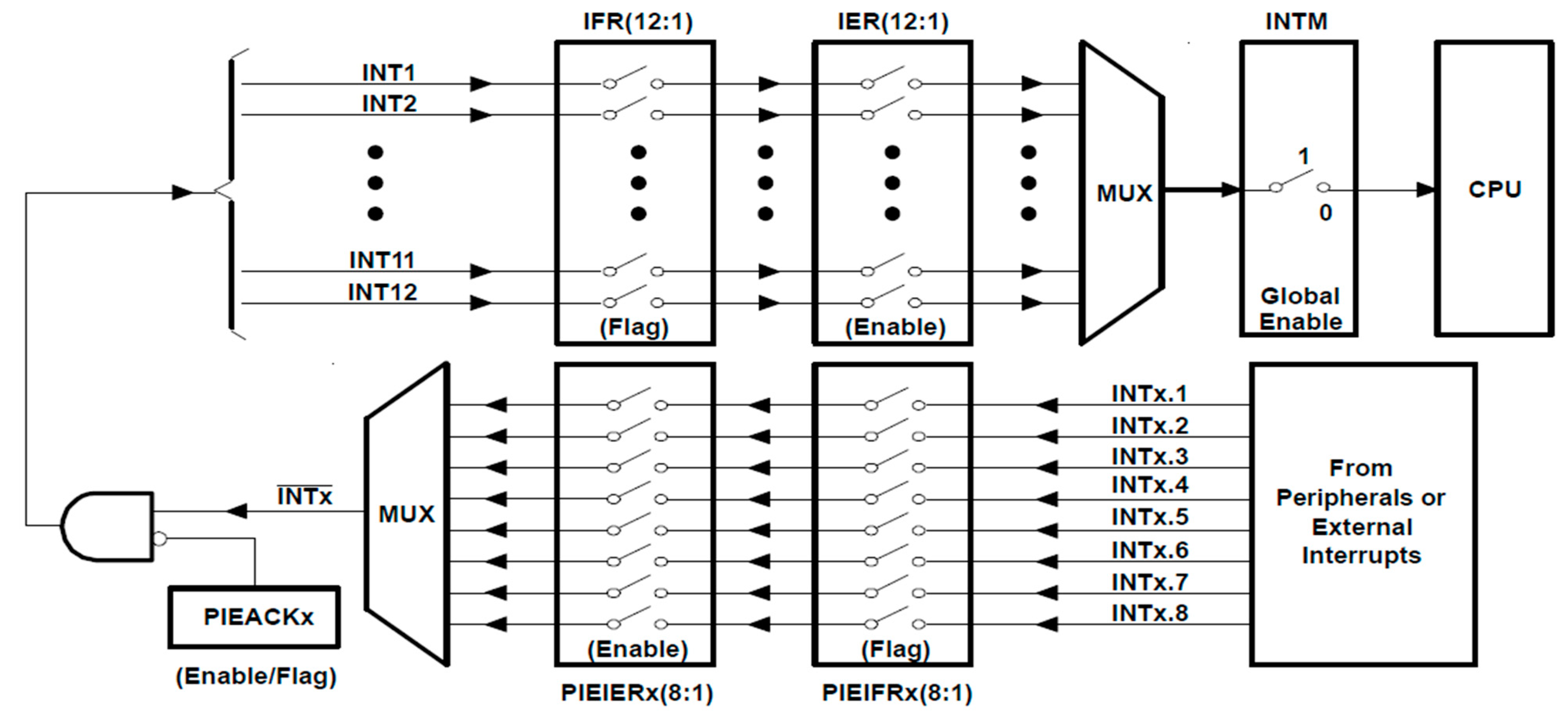
In order to realize the functions required by the user, each function of the DSP chip had a corresponding module and peripheral program, such as the GPIO module and EPWM module used in this study. Since each peripheral program will make one or more peripheral interrupt instruction(s) when a triggering event occurs, the CPU cannot process too many external interrupts in real-time, therefore, the Peripheral Interrupt Expansion (PIE) module was required.
The multiplexing interrupts diagram of the PIE module is shown in Figure 9. The PIE module of the TMS320F2808 chip could support up to 96 peripheral interrupt instructions, which could be divided into 8 groups (INTx.1~INTx.8), then further divided into 12 sources (INT1~INT12), and Global was set overall to enable the switch of the peripheral interrupt instruction. When the peripheral interrupt flag was enabled, the interrupt service program was called, after completion of the operation, the program counter was reset, Source and Group flags were eliminated, and acknowledgment was made, when an event was triggered, the program would run again.
When the program started to run, the system would eliminate the Source and Group interrupt flags in all PIE modules and vector tables to avoid misoperation. Then make the input and output arrangement of the GPIO, after the completion, make Global Enable enter the main program. The main program includes the background program for processing non-real-time events and the interrupt service program for processing real-time events. After the completion of the main program implementation, the reset will enable again.

4.2. Control Process of Crawler Tracks

When the TMS320F2808 chip received the packet sent from the Raspberry Pi end, the data in the packet was processed; the distance inputted was converted to the number of moving steps, then the crawler tracks move. To make a comparison of the number of steps to be moved and the feedback signal of the proximity switch through the subprogram of the proximity switch, when the two were the same, the crawler tracks immediately stopped, which indicated that the action had been completed, and it would continue to wait for the next packet. The flow chart of the moving subprogram of the crawler tracks is shown in Figure 10.

4.3. Control Process of the Mowing System

The main body of the mowing system was the mowing device. The optocoupler switch was used to receive the signal and the DSP TMS320F2808 chip was sent back to control the negative rotation of the motor. When the DC motor of the auxiliary steering started, the motor executed the right rotation, and when the left optocoupler switch was interrupted, the motor executed the left rotation. Similarly, when the right optocoupler switch was interrupted, the motor executed the right rotation until the instruction was completed. The reserve protection process was designed so that when the optocoupler switch does not send back the signal within six seconds, it was considered a hardware failure to stop the blade and steering motor. The mowing system flow chart is shown in Figure 11.

4.4. Communication Process

The communication protocol adopted in this study was RS-232. In the RS-232 standard, characters were transmitted one by one through a sequence of bit strings. The advantages were fewer transmission lines, simple wiring, and relatively long transmission distance, which was suitable for data transmission between the TMS320F2808 chip and the Raspberry Pi. The system first initialized and entered the waiting line, the TMS320F2808 chip then sends the initial code (0xFC), determines whether the Raspberry Pi was connected successfully, and if the Raspberry Pi sends back the same value, it meant that the line connection was successful, re-sending a receiving code (0xFE) meant that it allowed receipt of the packet. The Raspberry Pi sends a packet, the TMS320F2808 chip would have a packet with the size of six entering the stage of receiving, receiving the start code (0xFF) meant that the packet was placed in the first position of the array at the beginning of the packet. The fifth code of the packet was the addition of the 2nd, 3rd, and 4th codes. If an error occurred, the error would be displayed, and the waiting stage was entered. If the packet had no error, the end code (0xFD) would be received. The flow chart of the RS-232 communication protocol is shown in Figure 12.

4.5. Image Recognition Process

In this study, a webcam was used to capture images, and a Raspberry Pi was used for image recognition. If no obstacle was recognized, the packet would not be returned. If there was an obstacle, the captured image would be fuzzy processed, the picture would be converted into gray-scale, and then the frame reduction method would be used to identify the front object. If the identified object area exceeded the set value, the object in front is judged as an obstacle. The image recognition flow chart is shown in Figure 13.

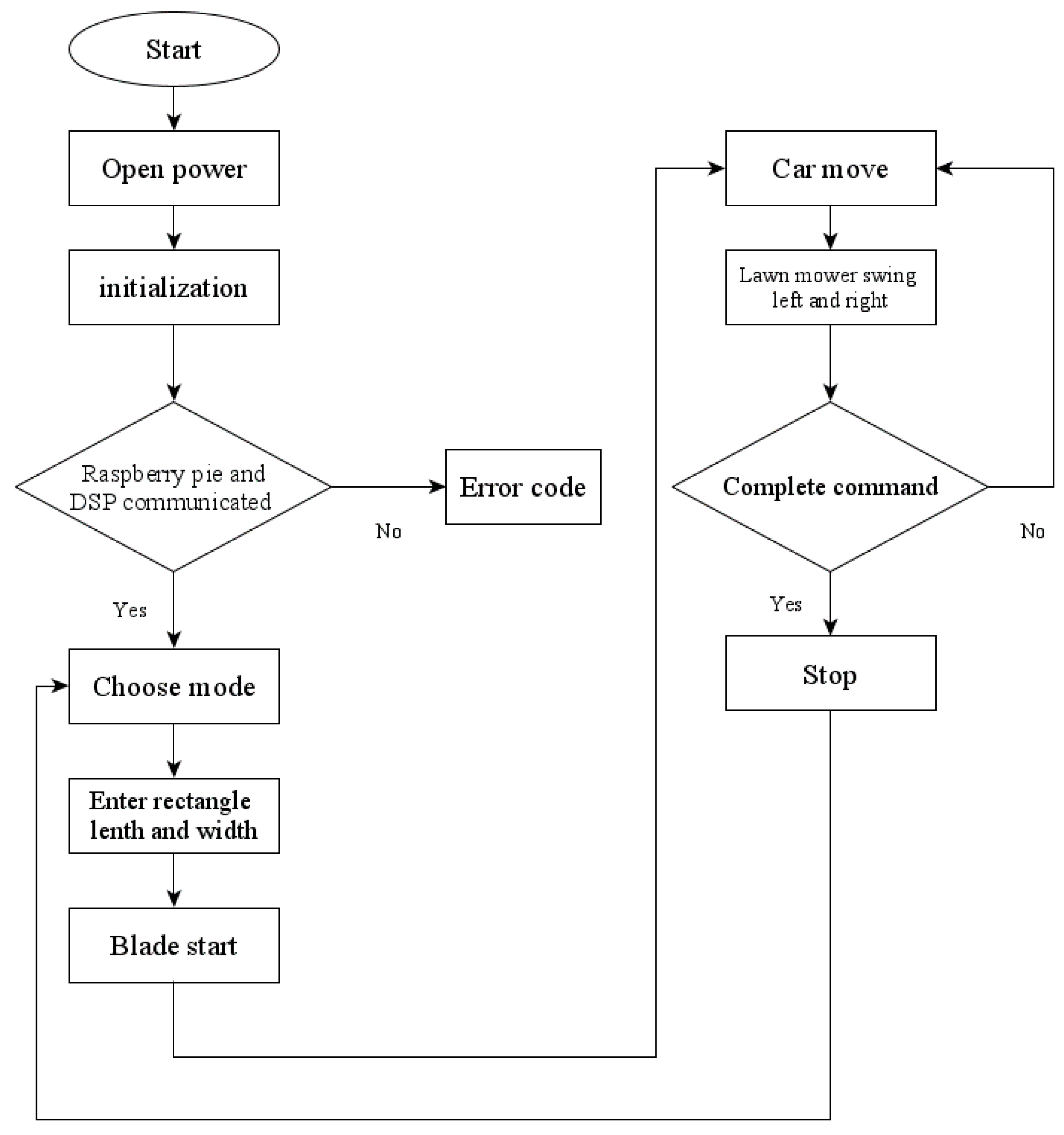
4.6. Control Process of the Automatic Robotic Lawn Mower

After the start-up of the power supply, the robotic lawn mower needs to wait for the connection between the Raspberry Pi and the human-machine interface, then the human-machine interface sends the communication packet, when the success of the communication was confirmed, modes could be chosen. Both side lengths of the rectangle were input after the blade had started for a few seconds. The crawler tracks and lawn mower operated and cooperated with the choice of the mode to complete the instruction. After the motor started, the PIR sensor module continuously detected for a warm body. If a warm body was detected within 2.4 m of the straight line, then all motors stopped action, the mode would need to be re-selected. The control process of the automatic robotic lawn mower is shown in Figure 14.

4.7. Warm Body Sensor

The circuit diagram applied to the warm body sensor in this study is shown in Figure 15. The module itself had automatic induction. When someone entered the induction range, a high potential was inputted; when someone left the induction range, it automatically delayed to shut down high potential and output low potential. LED could be used to tell that a human body had been detected in the front. After testing, the output high-potential voltage was about 3.3–3.6 V and the low-potential voltage was 0 V. The test waveform is shown in Figure 16.

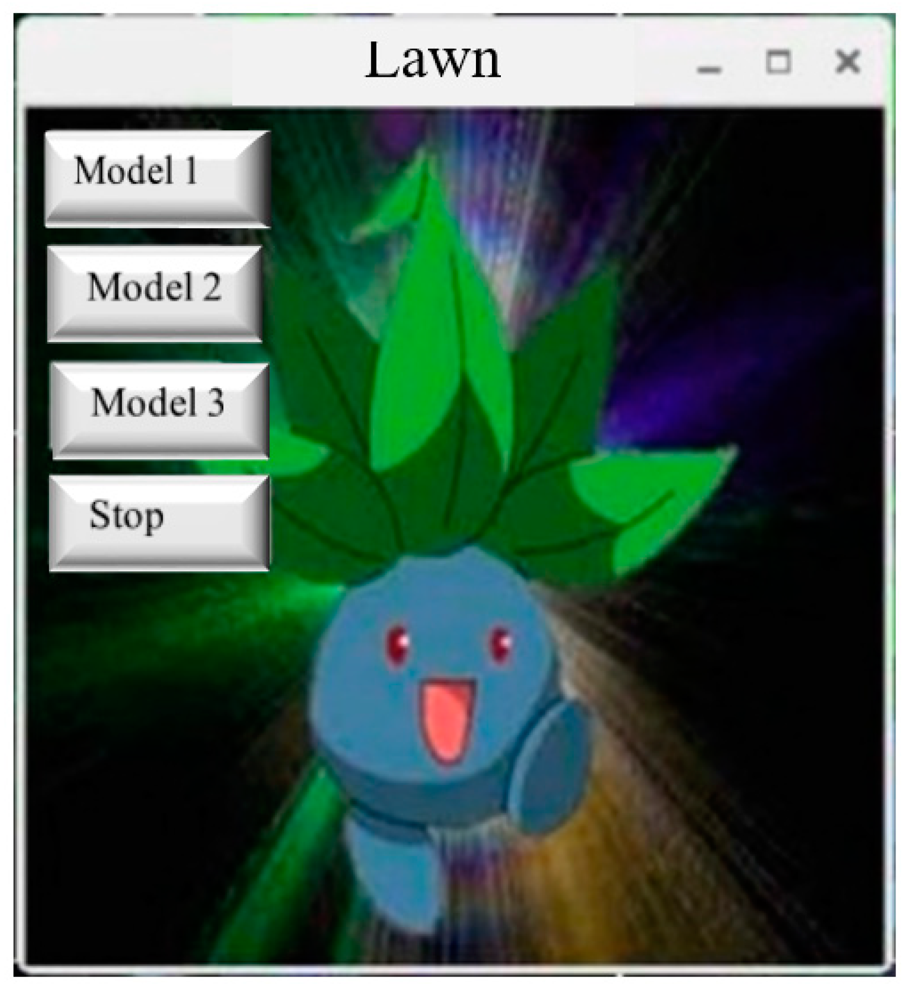
4.8. Human-Machine Interface Process

In this study, the human-machine interface was written by using Tkinter, an accessory program of Python, four buttons were made respectively, including Mode 1, 2, 3, and the emergency stop button. Mode 1 and Mode 2 were used to input the mowing area and to complete instructions in a bow path. Mode 1 was slow mode: The crawler tracks moved forward, and the mowing pole would swing to the left and right until the action was completed. Mode 2 was the inching mode: The crawler tracks would advance for a distance of half a blade, then stop, the mowing pole would swing once, and repeat the operation until the instruction was completed. Mode 3 was the obstacle avoidance mode: The crawler tracks moved forward, meanwhile the mowing pole would swing to the left and right. If the webcam identified obstacles on the way, it would send back the signal to the Raspberry Pi and then transmit the packet to the TMS320F2808 chip to command the crawler tracks to perform the obstacle avoidance function. In case of hardware and software failure, the emergency stop button could be used to stop the crawler tracks and the lawn mower motor. The human-machine interface displayed on the mobile phone is shown in Figure 17.

Actual Measurement of Image Recognition

The method of the Raspberry Pi combined with the frame subtract was used to identify whether there was an obstacle in front, which was used to imitate human eyes. For example, people would avoid the obstacle in front when moving. If the object identified exceeds the set value, the object in front would be regarded as an obstacle and marked on the window as shown in Figure 18.

4.9. Experimental Data of Robotic Lawn Mower

With other robots that use ultrasonic sensors to achieve the effect of avoiding obstacles, when the weeds on the ground are high, it is easy to regard the tall grass as an obstacle. This study used image recognition where it was less easy to misjudge this and utilized the method of frame subtract to identify whether there were obstacles ahead or not. This study designed and manufactured this robotic lawn mower from scratch. It has provided empirical study results. The “human-machine interface” and “image recognition” in this study were built on the Raspberry Pi. Therefore, this study used the more popular connection method VNC, to connect to the Raspberry Pi for remote control. Image recognition was the result of many experiments. During the study process, the situation of being unable to identify an obstacle was very rare, but image recognition is indeed the part that needs to be strengthened. Suggestions for a future study are when the light source is weak, a light source system could be installed on the car which can be turned on with the GPIO control of the Raspberry Pi to allow the webcam to identify any obstacles.
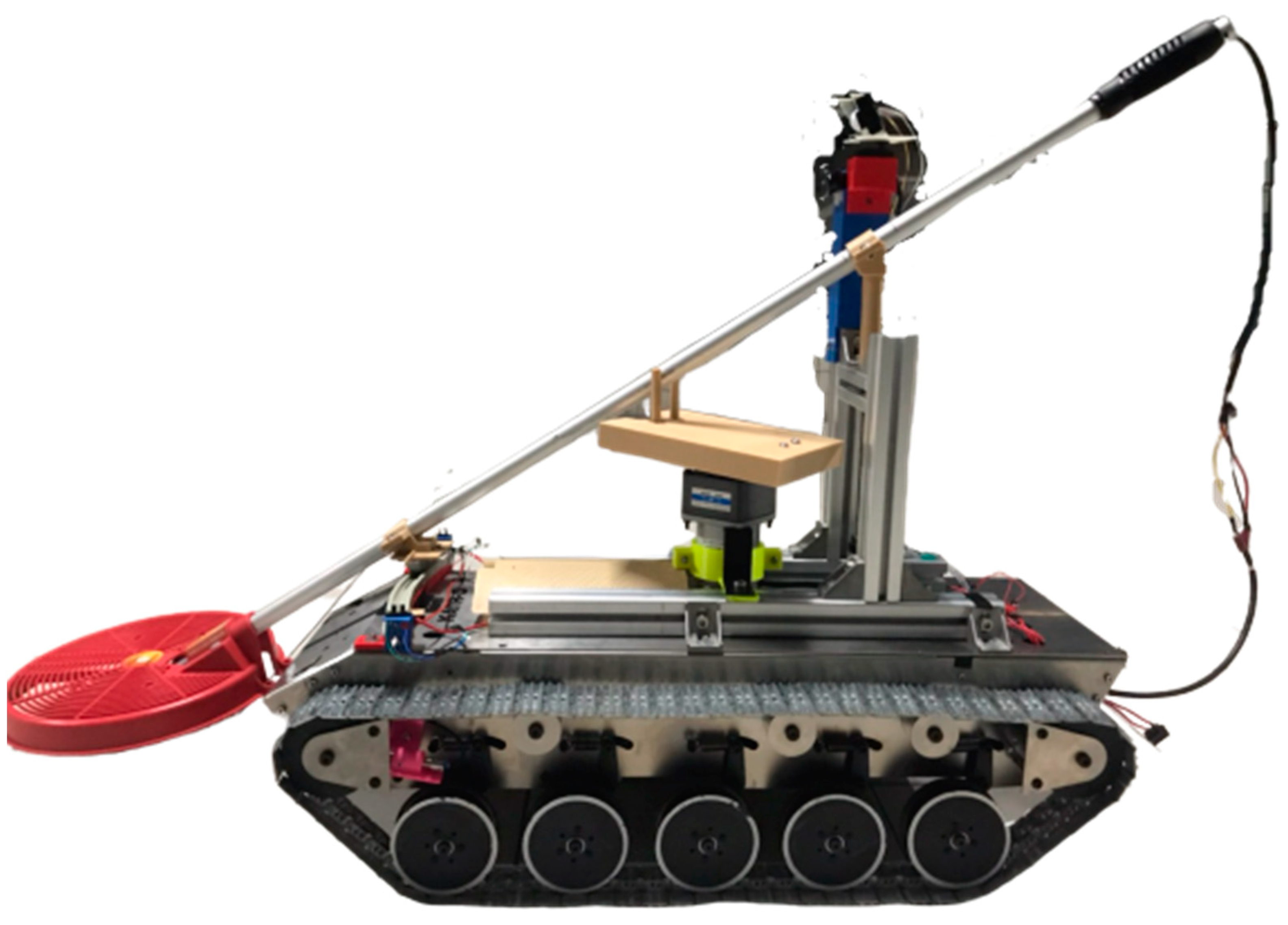
The crawler tracks in the study, could not only carry loads forward and climb the slope, but also do a 360° rotation, identify obstacles through webcam, achieve an obstacle avoidance function, combine the mowing structure, cooperate with the human-machine interface operation, and complete the remote control. The mowing blade could cut a distance of 55 cm for each swinging action. In the slow mode, an average mowing distance of 15 m could be completed per minute; in the inching mode, an average mowing area of 100 cm × 100 cm could be completed per minute, and the preferred mode could be selected based on different mowing needs. The finished product of the automatic robotic lawn mower is shown in Figure 19.

5. Discussion

Companies like Honda and Husqvarna have launched a number of robotic lawn mowers in recent years, at prices ranging from USD 1000 to 2500. Currently, robotic lawn mowers are more popular in the European market, but sales in the United States are not ideal. Some robotic lawn mowers of Swedish Husqvarna are sold at USD 5100/unit, which can handle difficult terrain with a slope of 45° and high weather resistance. With GPS-aided navigation and being driven by Automower Connect, lawn mowers can be controlled anywhere. Robotic lawn mowers launched by iRobot of the United States can memorize the positions and automatically generate a digital map of the area where the grass needs to be mowed. They can also be programmed to automatically mow regularly and control the height required for mowing. Users of the lawn mowers launched by Honda can let go of both hands without pushing them for mowing, and they can also warn against theft for $2500/unit. Robotic lawn mowers are quite varied and have different functions. Consumers can buy suitable models according to their own needs.
When robotic lawn mowers manufactured by Qiu, et al. [34] plan obstacle avoidance paths, ultrasonic waves and infrared rays are used, but this study found that if this method is used to avoid obstacles, misjudgment may occur due to weed interference. Therefore, this study does not use ultrasound but an image recognition function to deal with the obstacle avoidance path. Yu [35] points out that robotic lawn mowers face six problems: (1) When the working environment is complex, the information conveyed by sensors is not accurate enough; (2) The scope of work is difficult to be covered completely, and repeated work results in energy waste and reduced efficiency; (3) The communication function between the robot and the outside world is not strong, the human-machine interaction ability needs to be improved; (4) The positioning system is not accurate enough, which easily leads to the deviation of the working range; (5) The energy system is not good enough, and the ability to work continuously is weak; (6) The ability to learn is not strong enough to avoid repeated mistakes. In this study, robotic lawn mowers are developed from an academic point of view. In consideration of the cost problem, they cannot be compared with commercial lawn mowers on the market, but their functions and mowing performance have their advantages. It is hoped that when robotic lawn mowers are developed again, they can overcome the above problems as much as possible, and machinery with full functions, at an affordable price, and with excellent performance can be manufactured to meet the needs of consumers.

6. Conclusions

In this study, the Raspberry Pi is used as the human-machine interface platform, Python is the programming language, and its auxiliary program Tkinter is used for design; because lawn mowers can be dangerous, the human body infrared sensor is installed on the high platform of the crawler tracks to avoid accidents. When the human body infrared sensor acts, the warning message is displayed immediately on the human-machine interface and the lawn mower is stopped. The human-machine interface includes the obstacle avoidance mode using image recognition, the image processing function library used is OpenCV, obstacles are filtered with averaging fuzzy and thresholding procedures, and the obstacle avoidance action is further implemented. In this study, advanced image recognition technology is used to complete remote monitoring. Pictures taken by the image lens make the lawn mower achieve the effect of personification, and data are sent back to the system for subsequent processing, which is pioneering in productivity 4.0 sci-tech agriculture and is a contribution of this study.
The study direction of this study takes agricultural automation as the goal, considering new and old type lawn mowers, and referring to domestic and foreign robotic lawn mowers, it is decided that the conception of personification is added to complete the design of the robotic lawn mower with image recognition. The design of swinging to the left and right not only improves the range of mowing but also saves a lot of time and greatly increases work efficiency. The overall cost of the robotic lawn mower is not high. Farm commercialization can be developed in view of this price advantage. In the development of farm commercialization, users can input the required range through the easily-operated human-machine interface to complete mowing operation in a large area, which brings convenience for farmers, and also creates new opportunities for agricultural automation.

Suggestions for the Future

Due to the limitation of cost and time, there are still many ideas that cannot be realized in this study. The following are summarized in view of future research directions and suggestions:
  • Remote control mode can be added to the human-machine interface, buttons can be used to control various directions and angles of the crawler tracks and start or stop of the mowing motor. This mode can control the moving range of the robotic lawn mower more accurately and can display the remaining electrical charge of the robotic lawn mower on the screen to tell the user whether to charge it or not.
  • The fixing device of the mowing device system uses 3D printing equipment. To avoid wire wear, a stronger iron sheet or aluminum material can be used instead, the position of the optocoupler sensor can be adjusted, and the baffle plate structure can be redesigned to reduce the error range.
  • In terms of image processing, it is hoped to strengthen the identification of obstacles, increase the accuracy of identification of obstacles and return coordinates, identify the specific size, area, and circumference of objects, and then take obstacle avoidance actions.

Author Contributions

J.-C.L. developed the main framework. S.-H.C. the manuscript in writing the paper, review and editing. Z.-Y.Z., B.-W.W., Y.-J.C. formal analysis and investigation, Y.-J.C. validation. All authors have read and agreed to the published version of the manuscript.

Funding

This research received no external funding.

Institutional Review Board Statement

Not applicable.

Informed Consent Statement

Not applicable.

Data Availability Statement

The data are available from the corresponding author upon request.

Acknowledgments

Authors thank Yu-Feng Zhu teacher, Oriental Institute of Technology, for helping to make the circuit board, so that the hardware circuit can run smoothly. Thanks for senior’s help, I have learned PCB drawing, image recognition, 3D printing and other related technologies.

Conflicts of Interest

The authors declare no conflict of interest.

References

  1. Chen, Y.S.; Tsao, H.H.; Chen, S.W.; Liu, C.Y.; Yeh, L.C. An integrated study on the recognition system of the mature fruit. Electron. Commer. Stud. 2018, 16, 233–258. [Google Scholar]
  2. Waleed, M.; Um, T.W.; Kamal, T.; Khan, A.; Iqbal, A. Determining the precise work area of agriculture machinery using internet of things and artificial intelligence. Appl. Sci. 2020, 10, 3365. [Google Scholar] [CrossRef]
  3. Xie, G.; Lu, W. Image edge detection based on OpenCV. Int. J. Electron. Electr. Eng. 2013, 1, 104–106. [Google Scholar] [CrossRef]
  4. Naranjo-Torres, J.; Mora, M.; Hernández-García, R.; Barrientos, R.J.; Fredes, C.; Valenzuela, A. A review of convolutional neural network applied to fruit image processing. Appl. Sci. 2020, 10, 3443. [Google Scholar] [CrossRef]
  5. Wirtz, J.; Patterson, P.G.; Kunz, W.H.; Gruber, T.; Lu, V.N.; Paluch, S.; Martins, A. Brave new world: Service robots in the frontline. J. Serv. Manag. 2018, 29, 907–931. [Google Scholar] [CrossRef] [Green Version]
  6. Belanche, D.; Casaló, L.V.; Flavián, C.; Schepers, J. Service robot implementation: A theoretical framework and research agenda. Serv. Ind. J. 2020, 40, 203–225. [Google Scholar] [CrossRef] [Green Version]
  7. Wang, N.; Yeung, D.Y. Learning a deep compact image representation for visual tracking. Adv. Neural Inf. Process. Syst. 2013, 809–817. [Google Scholar]
  8. Genesys. U.S. Employers Expect Growth of Artificial Intelligence in the Workplace but Not Major Job Reductions. 2019. Available online: https://www.prnewswire.com/news-releases/usemployers-expect-growth-of-artificial-intelligence-in-the-workplace-but-not-major-jobreductions-300901926.html (accessed on 12 September 2020).
  9. International Federation of Robotics. World Robotics Report 2018. Press Conference Summary, Tokyo. 2018. Available online: https://ifr.org/free-downloads/ (accessed on 12 September 2020).
  10. Huang, M.H.; Rust, R.T. Artificial intelligence in service. J. Serv. Res. 2018, 21, 155–172. [Google Scholar] [CrossRef]
  11. Rajan, K.; Saffiotti, A. Towards a science of integrated AI and robotics. Artif. Intell. 2017, 247, 1–9. [Google Scholar] [CrossRef] [Green Version]
  12. Velichko, A. Neural network for low-memory IoT devices and MNIST image recognition using kernels based on logistic map. Electronics 2020, 9, 1432. [Google Scholar] [CrossRef]
  13. Van Doorn, J.; Mende, M.; Noble, S.M.; Hulland, J.; Ostrom, A.L.; Grewal, D.; Petersen, J.A. Domo arigato Mr. Roboto: Emergence of automated social presence in organizational frontlines and customers’ service experiences. J. Serv. Res. 2017, 20, 43–58. [Google Scholar] [CrossRef] [Green Version]
  14. Sánchez, J.M.; Rodríguez, J.P.; Espitia, H.E. Review of artificial intelligence applied in decision-making processes in agricultural public policy. Processes 2020, 8, 1374. [Google Scholar] [CrossRef]
  15. Yoon, Y.H.; Hwang, D.H.; Yang, J.H.; Lee, S.E. Intellino: Processor for embedded artificial intelligence. Electronics 2020, 9, 1169. [Google Scholar] [CrossRef]
  16. Afzaal, H.; Farooque, A.A.; Abbas, F.; Acharya, B.; Esau, T. Computation of evapotranspiration with artificial intelligence for precision water resource management. Appl. Sci. 2020, 10, 1621. [Google Scholar] [CrossRef] [Green Version]
  17. Kalpakjian, S.; Schmid, S.R.; Sekar, K.S. Manufacturing Engineering and Technology; Pearson: Upper Saddle River, NJ, USA, 2014. [Google Scholar]
  18. Kolbeinsson, A.; Lagerstedt, E.; Lindblom, J. Foundation for a classification of collaboration levels for human-robot cooperation in manufacturing. Prod. Manuf. Res. 2019, 7, 448–471. [Google Scholar] [CrossRef]
  19. Kang, M.; Lee, Y.; Park, M. Energy efficiency of machine learning in embedded systems using neuromorphic hardware. Electronics 2020, 9, 1069. [Google Scholar] [CrossRef]
  20. Yeh, Y.J.; Cheng, Y.T.; Tsai, C.B.; Yeh, Y.M. The framework of the intelligent video surveillance and the streaming protection. J. Adv. Technol. Manag. 2012, 2, 93–106. [Google Scholar]
  21. Wang, C.C.; Lien, S.F.; Ye, Z.X.; Li, C.J.; Jhang, G.M. Implementation of path planning in robot arms using image recognition technique. J. Adv. Eng. 2017, 12, 19–22. [Google Scholar]
  22. Huang, G.T.; Tsai, Y.H.; Lu, X.J.; Zhang, G.H.; Li, W.C. Technology and application of smart vision system in lighting control. J. Ind. Mechatron. 2020, 446, 69–73. [Google Scholar]
  23. Kandel, I.; Castelli, M. Transfer learning with convolutional neural networks for diabetic retinopathy image classification. A review. Appl. Sci. 2020, 10, 2021. [Google Scholar] [CrossRef] [Green Version]
  24. Liaqat, S.; Dashtipour, K.; Arshad, K.; Ramzan, N. Non invasive skin hydration level detection using machine learning. Electronics 2020, 9, 1086. [Google Scholar] [CrossRef]
  25. Kabe, G.K.; Song, Y.; Liu, Z. Optimization of FileNet for liver lesion classification. Electronics 2020, 9, 1237. [Google Scholar] [CrossRef]
  26. Rghioui, A.; Lloret, J.; Harane, M.; Oumnad, A. A smart glucose monitoring system for diabetic patient. Electronics 2020, 9, 678. [Google Scholar] [CrossRef]
  27. Sun, L. Analysis of the development of robotic lawn mowers based on patent applications. China Invent. Pat. 2019, 16, 49–54. [Google Scholar]
  28. Zadeh, L.A. Fuzzy Sets. Inf. Control. 1965, 8, 338–353. [Google Scholar] [CrossRef] [Green Version]
  29. Lin, H.H. Application of a fuzzy decision model to the design of a pillbox for medical treatment of chronic diseases. Appl. Sci. 2019, 9, 4909. [Google Scholar] [CrossRef] [Green Version]
  30. Liu, C.C.; Chen, J.J. Analysis of the weights of service quality indicators for drone filming and photography by the fuzzy analytic network process. Appl. Sci. 2019, 9, 1236. [Google Scholar] [CrossRef] [Green Version]
  31. Yin, J.; Zhu, D.; Liao, J.; Zhu, G.; Wang, Y.; Zhang, S. Automatic steering control algorithm based on compound fuzzy PID for rice transplanter. Appl. Sci. 2019, 9, 2666. [Google Scholar] [CrossRef] [Green Version]
  32. Liu, S.Y.; Wang, Y.C. A study of applying fuzzy theory in simulation-based education. Appl. Sci. 2019, 9, 1989. [Google Scholar] [CrossRef] [Green Version]
  33. Cárdenas, J.R.G.; Nebot, À.; Mugica, F. Integral seismic risk assessment through fuzzy models. Appl. Sci. 2020, 10, 3017. [Google Scholar] [CrossRef]
  34. Qiu, B.J.; Qian, G.H.; Zhou, N.; Cui, S.J. Avoiding barriers control of mowing robot. J. Jiangsu Univ. 2005, 26, 285–288. [Google Scholar] [CrossRef]
  35. Yu, B. Market research on intelligent mowing robot. Technol. Innov. Appl. 2018, 29, 70–71. [Google Scholar]
Figure 1. System architecture of the automatic robotic lawn mower.
Processes 09 00358 g001
Figure 2. Environmental interface of Code Composer Studio (CCS) v6.0.
Processes 09 00358 g002
Figure 3. Motor drive system diagram.
Processes 09 00358 g003
Figure 4. Motor drive circuit diagram.
Processes 09 00358 g004
Figure 5. PCB (Printed Circuit Board) layout of the motor drive circuit.
Processes 09 00358 g005
Figure 6. System of the gate driver IC FAN7842.
Processes 09 00358 g006
Figure 7. Gate driver control diagram.
Processes 09 00358 g007
Figure 8. Mowing device power supply system.
Processes 09 00358 g008
Figure 9. Interrupt multiplexing diagram of the Peripheral Interrupt Expansion (PIE) module.
Processes 09 00358 g009
Figure 10. The flow chart of the moving subprogram of the crawler tracks.
Processes 09 00358 g010
Figure 11. Control process of the mowing system.
Processes 09 00358 g011
Figure 12. The flow chart of RS-232 communication protocol.
Processes 09 00358 g012
Figure 13. Image recognition process flow chart.
Processes 09 00358 g013
Figure 14. Control process of an automatic robotic lawn mower.
Processes 09 00358 g014
Figure 15. The circuit diagram of a warm body sensor.
Processes 09 00358 g015
Figure 16. Output data of PIR.
Processes 09 00358 g016
Figure 17. The human-machine interface displayed on the mobile phone.
Processes 09 00358 g017
Figure 18. Obstacles ahead are marked in the window.
Processes 09 00358 g018
Figure 19. The finished product of the automatic robotic lawn mower.
Processes 09 00358 g019
Publisher’s Note: MDPI stays neutral with regard to jurisdictional claims in published maps and institutional affiliations.

