1. Introduction
Glycerol is a valuable component obtained from renewable sources. It is considered a by-product in the production of biodiesel by transesterification of vegetable oils or animal fats. Biodiesel industry produces 1 kg glycerol/9 kg biodiesel [
1]. Biodiesel production has been increasing for the last 20 years [
2], and the supply of glycerol exceeds demand. While there are no alternative uses for glycerol, the falling prices of glycerol will continue. Therefore, glycerol appears as a low-cost raw material for chemical synthesis, with great potential for different products [
3].
One of the alternatives is glycerol’s chemical transformation to propanediol, whose main products are 1,2 and 1,3 propanediol, ethylene glycol, and other subproducts, such as lactic acid, acetol, acrolein, propanol, methanol, methane, and CO
2 [
4]. The main uses of propanediol are cosmetics products, antifreeze, pharmaceuticals, and others. To laboratory-scale, the investigations about glycerol conversion to propanediol are carried out in microreactors [
4,
5,
6]. However, in those reactors, an intrinsic kinetic can only be obtained, which is useful on a theoretical scale but cannot be used for industrial process design due to the reactor’s complexity in terms of its hydrodynamic parameters.
Generally, the catalysts are supported on rhodium (Rh) [
7], Ru [
5,
8], platinum (Pt) [
9], and Cu/Zn/Al [
6], and depending on these catalysts, the reaction mechanism to 1,2 propanediol production from glycerol is different. In the liquid phase, the hydrogenolysis is carried out at high hydrogen pressures and temperatures. However, other lateral reactions appear in which the glycerol is transformed into other subproducts. An alternative to overcome it is a process in two steps: dehydration under vacuum conditions and hydrogenation under a hydrogen atmosphere.
This study aims to select an appropriate reactor to carry out the reaction on an industrial scale. Its modeling and sizing are at laboratory scale, keeping in mind the hydrodynamic and mass transfer limits, to obtain estimates from the process for industrial scale up.
2. Materials and Methods
The methodology is presented in several sections: initially, the reactor’s selection is described, then hydrodynamic parameters are presented. The sizing at a laboratory scale of the proposed reactor is given, and finally, its simulation considering chemical kinetics and mass transfer, as well.
2.1. Reactor Type Selecting
In accordance with the different phases of the components involved in the heterogeneous reaction (glycerol in liquid phase, hydrogen in gaseous phase, and the catalyst in solid phase), selecting suitable equipment was necessary to ensure the best gas–liquid–solid contact. Different types of reactors were considered: cavitation and catalytic trickle bed, suspended bed, and fluidized bed. Taking the hydrodesulfurization [
10,
11,
12] as an industrial precedent that occurs at very similar conditions to the reaction of formation of 1,2 propanediol [
4] (on the 300 °C and 34 bars) and that both reactions require that the catalyst remains in contact with the liquid and the gas, it was decided to select the trickle bed as reactor for the development of this project.
The selection of this type of reactor has important features from the point of view of its industrial implementation and its scaling point in the laboratory. Unlike the micro-reactor in which laboratory tests are performed for the obtention of intrinsic kinetics, in this type of reactor, hydrodynamic effects and mass transfer limitations cannot be dismissed; this requires much more complex models. At an industrial level, as the reactor’s size increases considerably, the effects of mass transfer and the hydrodynamic conditions of operation are determining factors in the success of the process. That is to say that the efficiency obtained at the microlaboratory reactor level will be different from that which would be obtained in the trickle bed reactor at laboratory scale and much more than what can be obtained in optimal conditions on an industrial scale. The selection of this equipment is challenging in the modeling and simulation of the reactor, since other variables not considered at laboratory scale are required for industrial sizing.
Other important considerations that must be taken into account are phenomena at macro, meso, and micro scales that control the overall efficiency of the reaction and are associated with certain hydrodynamic features and flow regimes within the reactor [
13].
2.2. Hydrodynamic Parameters
Pressure drop is one of the most important hydrodynamic parameters for both the operation and the reactor design. The pressure drop is a function of the reaction equipment sizing (diameter of the column, type, and size of the particles of catalyst), the parameters of operation (flow rates of gas and liquid), and the properties of the fluids (surface tension, viscosity, and density). The studied reaction is carried out at high temperatures and pressures. The Sang et al. [
14] equation can be used as a referent in high pressures operations in trickle bed reactors.
where
dh is the hydraulic diameter,
GG is the gas’s surface speed, Re is the Reynolds number, We is the Weber number, and
XG is the modified Lockhart–Martinelli number. This equation is valid for making predictions between 0.2 and 8.1 MPa.
Liquid holdup in trickle bed reactors is expressed in two ways: (i) total liquid holdup (ϵL), defined as volume of liquid per unit of bed volume, and (ii) liquid saturation (βL), defined as the volume of liquid per void unit instead of bed volume unit. The liquid holdup can be divided in two parts: dynamic liquid holdup (ϵLd) and static liquid holdup (ϵLs). Static liquid holdup can be defined as the volume of liquid per unit of volume of the bed remaining in the bed after its draining. The importance of the liquid holdup in this type of reactor is its influence on the residence time, the efficiency of the wetting, and heat and mass transfer.
There are several correlations that can predict the liquid holdup at high pressures [
15,
16,
17]; however, by its simplicity, the correlation of Larachi [
14] stands out:
where
βe is the external saturation.
Wetting of the catalyst particles is one of the most important parameters in the reactor’s operation and for its design. This phenomenon is unique in the trickle bed reactors, and its quantification is a daunting task. Wetting can be divided into external and internal, the first being the portion of the surface area of the catalytic particle covered by the liquid and the second being the portion of the catalyst’s internal surface covered by the liquid. The formation of a liquid film on the catalyst requires the gas to disseminate through the liquid, restricting its arrival to the solid phase where it is adsorbed on the catalyst’s active sites. Depending on what phase the limit reagent is, the effects of external wetting are different. If the limit reagent is found in the fluid, then the reaction speed is directly proportional to the amount of catalyst that is covered by the liquid film. The reaction speed increases as the wetting diminishes, because the gas can be adsorbed in the catalyst’s active sites without going through the liquid’s phase mass transfer resistance. The following equation is valid in ranges of 0.31 to 5 MPa.
where
Ga is Galileo´s number,
2.2.1. Mass Transfer within the Reactor
Due to gas–liquid–solid contact, it is possible to identify three types of mass transfer phenomena, which limit the reaction’s development: the gas–liquid, liquid–solid and gas–solid consecutive mass transfer.
2.2.2. Gas–Liquid Mass Transfer Coefficients
The mass transfer coefficient between gas and liquid depends on several parameters, including the catalytic particles size, the liquid and gas flows, fluid properties, and the reactors conditions of operation. There are plenty of correlations that allow obtaining the mass transfer coefficient (
kGL aGL) [
18]. Some correlations [
19] consider the dynamic liquid holdup and the pressure drop.
The pressure drop is an unknown parameter in the reactor; therefore, it is necessary to estimate or measure it experimentally. Other correlations [
20] are proposed using known parameters.
where
Other authors [
21] considered desirable different sizes of catalyst.
where
Sh is a Sherwood number,
is a Reynolds number, and
Sc is a Schmidt number.
2.2.3. Liquid–Solid Mass Transfer Coefficients
Liquid–solid mass transfer coefficients are also required in the operation of a trickle bed reactor, as well as the mass transfer coefficient between gas and solid. The first one depends on the contact of the liquid with the solid surface; therefore, is dependent of the wetting of the catalytic surface. Considering this fact, it is possible to find correlations that include the wetting fraction.
Table 1 shows it is possible to observe some values for a and b for Equation (15).
Equation (10) only applies to particles of about 5 mm.
2.2.4. Gas–Solid Transfer Coefficients.
The gas–solid mass transfer coefficient is another factor that is required in the modeling of the trickle bed reactor when particles are partially wet. In the catalyst’s dry surface, there is a direct contact between the reagents in the gaseous phase and the outer surface of the catalyst. The gas–solid mass transfer has been studied extensively in single phase systems. For Re > 10, the correlation of Dwivedi et al., 1977 [
25], stands out.
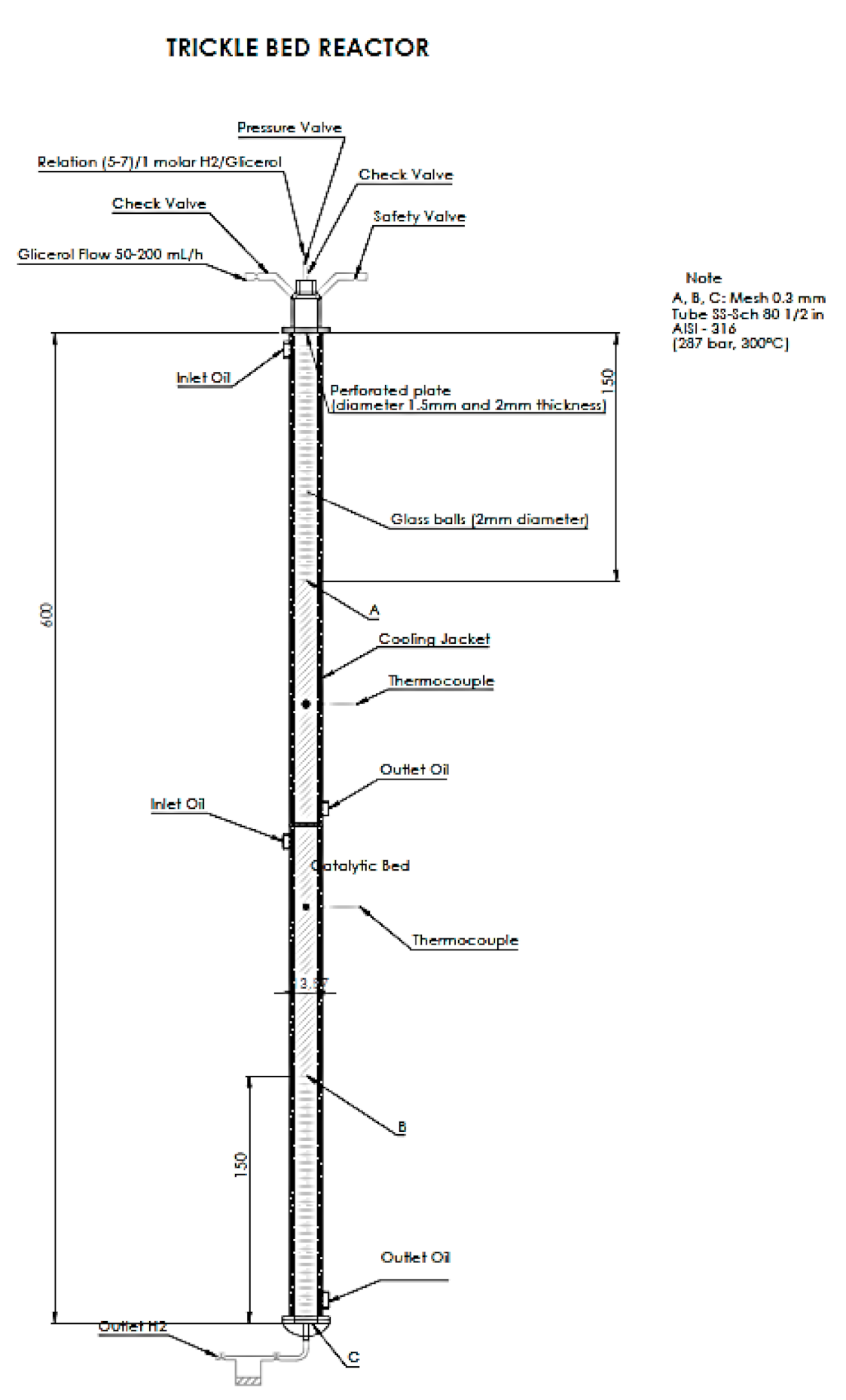
2.3. Dimensions of the Trickle Bed Reactor to Laboratory Scale and other Considerations
Listed below are some of the variables necessary for the reactor sizing. Since the internal diameter of the laboratory reactors must not exceed 1.5 cm, it was decided to use a diameter of 1.25 cm. The selected length was 60 cm, effective for the bed in which we could put both catalysts as glass spheres. This bed was packed with about 30 cm of catalyst between 1 and 2 mm of glass to increase the wetting. The reactor must withstand pressures up to 200 bars, as the reaction occurs between 20 and 100 bars [
6]. Flow regulators must be designed to effectively control flows between 10 and 150 mL/h for the liquid. The molar flow of hydrogen must be calculated based on the molar rate of 5:1 of hydrogen to glycerol.
The catalysts MK 121, from Haldor Topsoe and HIFUEL W220, and HIFUEL W230, from Alfa Aesar, were selected because of their similarity to the described in [
6]. However, these catalysts come in cylinders of various sizes and must be reduced to achieve the desired particle size between 0.22 mm and 0.8 mm. To reduce the resistance to the mass transfer, the catalysts must be activated according to the manufacturer’s specifications. The heating can be done with hot oil, and temperature control must be able to function effectively between 100 °C and 300 °C, since the reaction occurs at 200 °C (100% oversizing). Reactor and laboratory equipment must strictly fulfill all regulations to handle an explosive gas such as hydrogen.
All electrical components must have protection against spark and be duly certified. The continuous phase within the reactor must be gas, and the dispersed phase that flows through the walls of the surface of the catalyst particles must be the liquid. This condition must be ensured through diffusers and other measures as may be necessary for reactor’s correct operation. In addition, glass spheres of 2 mm diameter must be placed before and after the catalytic bed to facilitate the flow and heat transfer.
Figure 1 and
Table 2 show the laboratory scale trickle bed reactor’s design criteria and compare it with the recommended in [
26].
2.4. Kinetic Model
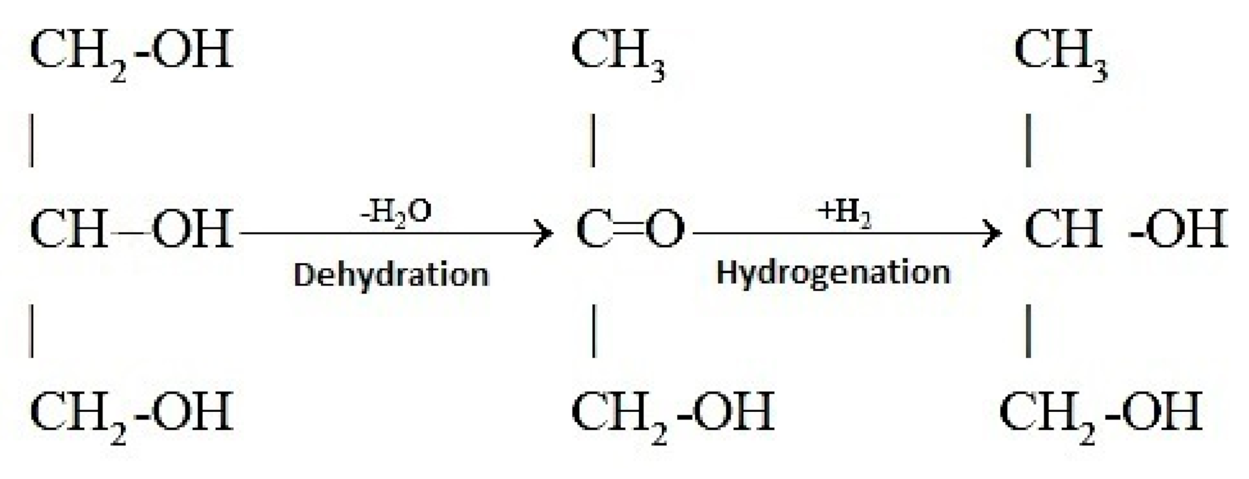
The glycerol hydrogenolysis reaction in the presence of a Cu/Zn/To catalyst produces 1,2 propanediol and acetol as an intermediate product. The mechanism described by [
4] proposes the acetol as an intermediary and is valid for catalysts containing Cu (
Figure 2).
The kinetics proposed by [
6] is based on the presumption of two different sites of adsorption for hydrogen and organic molecules:
where the subscripts
A,
G,
H, and
P indicate acetol, glycerol, hydrogen, and 1,2 propanediol, respectively. This mechanism was obtained in a differential reactor, and it was found that the resistances from the mass transfer were negligible at the time of the experiment (mostly due to previous particle size adequacy to assure this condition); it can be considered as an intrinsic kinetics.
2.5. Simulation with the Kinetic Model
Embedding this kinetic model in the mass balance of a trickle bed reactor, it is possible to predict the behavior of the reactor at a laboratory scale for the conditions shown in the
Table 3.
The mass balance equations in the bed are
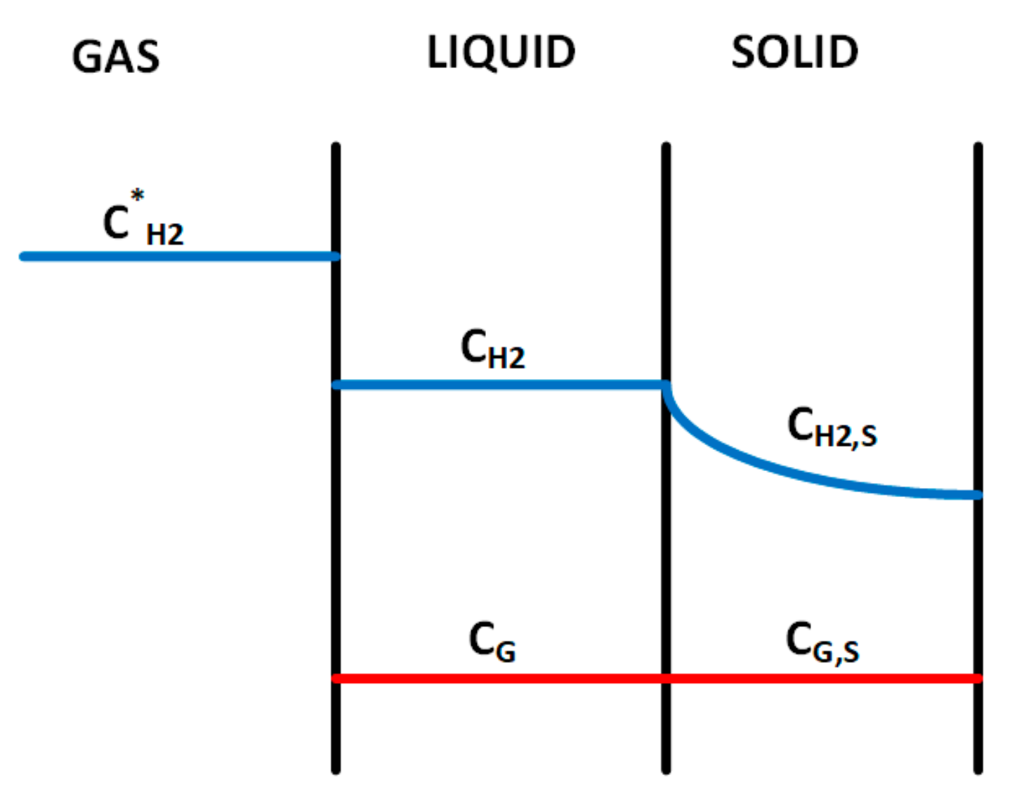
2.6. Model with Mass Transfer and Key Parameters
The kinetic model neglects all mass transfer restrictions and assumes the reagents as the only limiting factor for the reaction. However, the mass transfer limits the actual operation of this type of reactors.
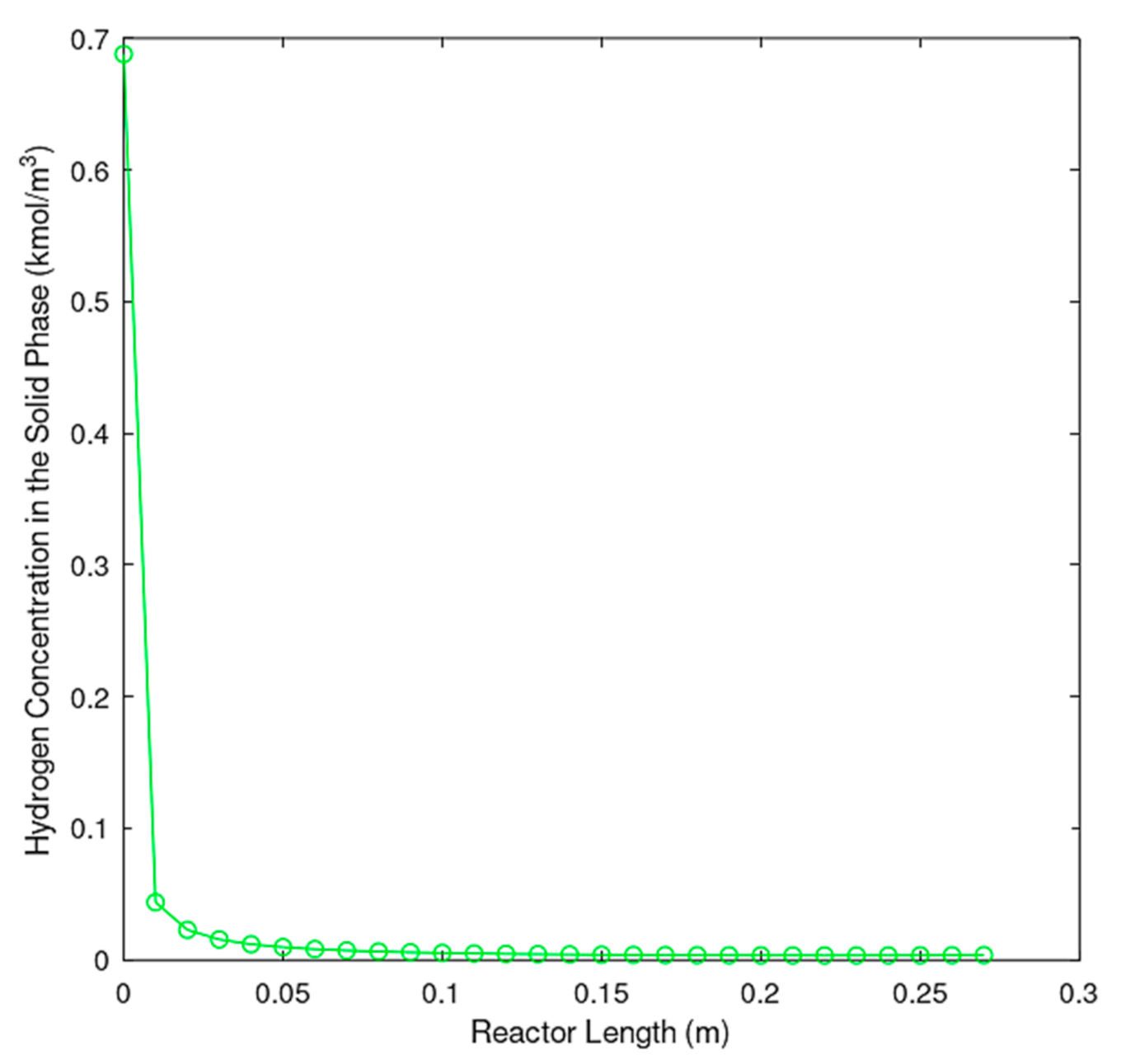
Figure 3 illustrates how hydrogen concentration decreases drastically in the solid catalyst, where it is adsorbed, compared with its concentration in the gas phase.
Using the kinetic model as a basis, it is possible to create a model that considers both mass transfer as well as operation parameters, such as wetting [
27].
The first reaction occurs only in the liquid phase and is subject to the wetting, limiting its efficiency. In the case of the second reaction, which involves two phases, the following model is used:
Given that the liquid phase participates in this reaction, the wetting factor also limits the reaction. However, the restrictions of mass transfer of liquid phase to hydrogen applied only in the wet part, hence, r2 is based on the concentration of hydrogen in the solid phase (CH2), while r2* is a function of the concentration of hydrogen in the gas phase (CH2*). It is possible to formulate this model in this way, because it is assumed that the streams (also referred to as rivulets in the literature) that cover the bed are not fixed and move throughout the bed, renewing the adsorption of the liquid substances. Thus, the reaction also occurs in areas of the catalyst that are not covered by the liquid film but that have been wetted randomly.
3. Results and Discussion
Using parameters shown in
Table 3, along with Equations (21 and 22), and using Aspen Custom modeler as a simulation engine, it was possible to simulate the laboratory scale reactor’s behavior assuming negligible mass transfer. Also, using Equation (15) along with
Table 1 and parameters reported in [
22], a wetting factor of 0.9 was calculated, and the reactor, under the assumption of non-negligible mass transfer, was simulated.
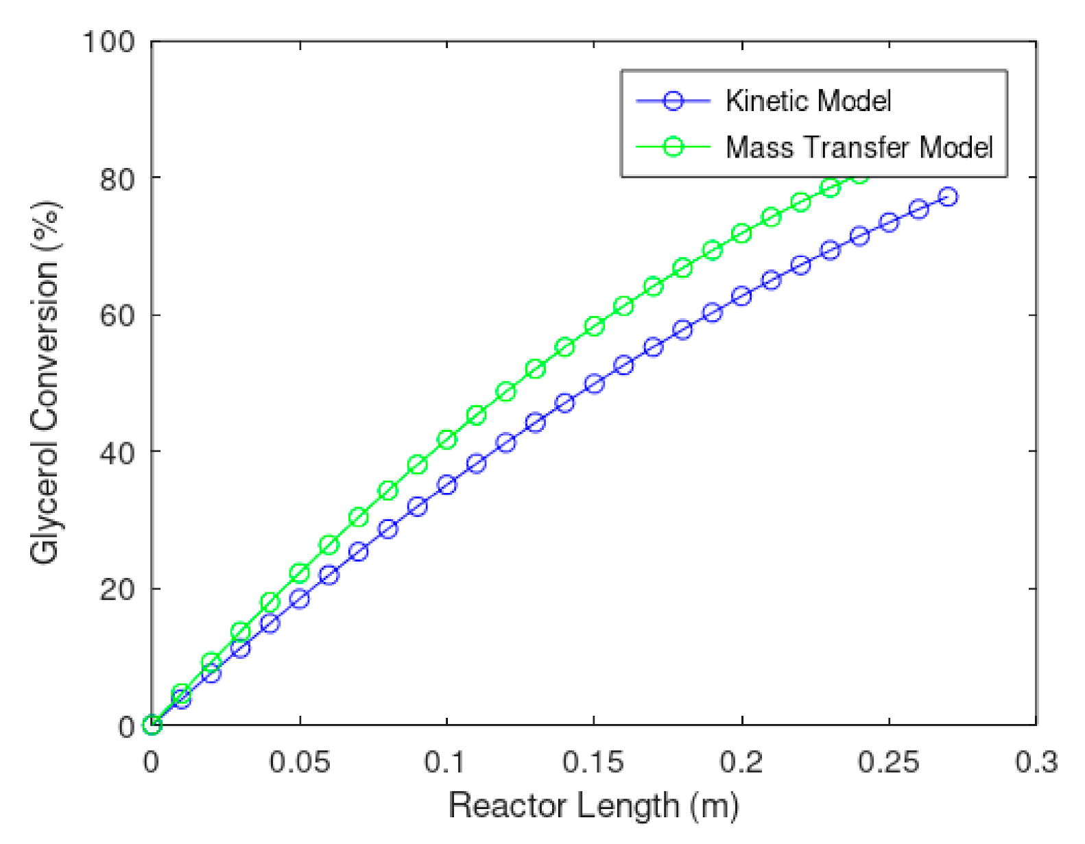
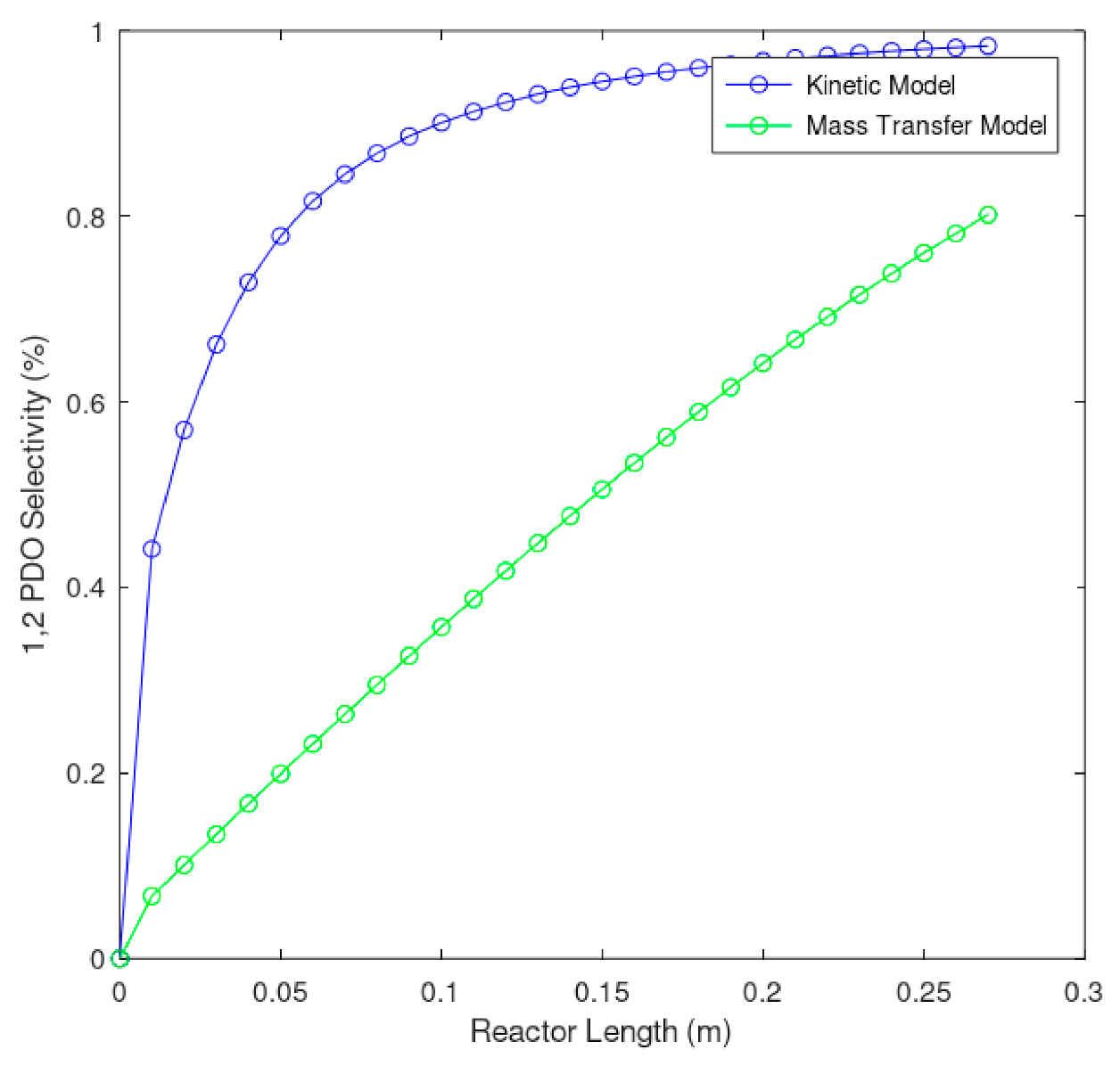
Figure 4 and
Figure 5 show the result of the simulation of the kinetic model as well as the mass transfer model proposed for the laboratory scale reactor.
Figure 4 shows an unusual behavior in the reactor: it is noticeable that the mass transfer model presents a higher glycerol conversion than the kinetic model. It also shows that expected glycerol conversion (
Figure 4) increased while the expected 1,2 propanediol selectivity (
Figure 5) decreases due to mass transfer limitations. However, these results remained well inside the limits reported in the literature, between 75 and 98.2% for most of the catalysts [
28,
29,
30].
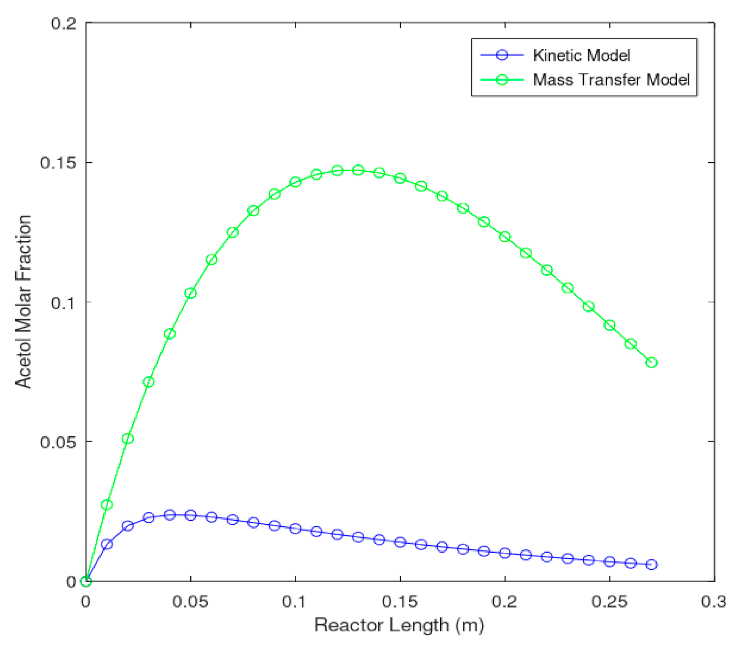
Figure 6 shows acetol molar fraction along the reactor. It can be observed that the mass transfer model presented significantly higher values than the kinetics model for acetol molar concentration. This, in part, can explain
Figure 4 results. The mass transfer model produced higher acetol concentration due to the low solubility of hydrogen in the liquid phase that promotes acetol accumulation, as the hydrogenation reaction (reaction 2) is mass transfer-limited.
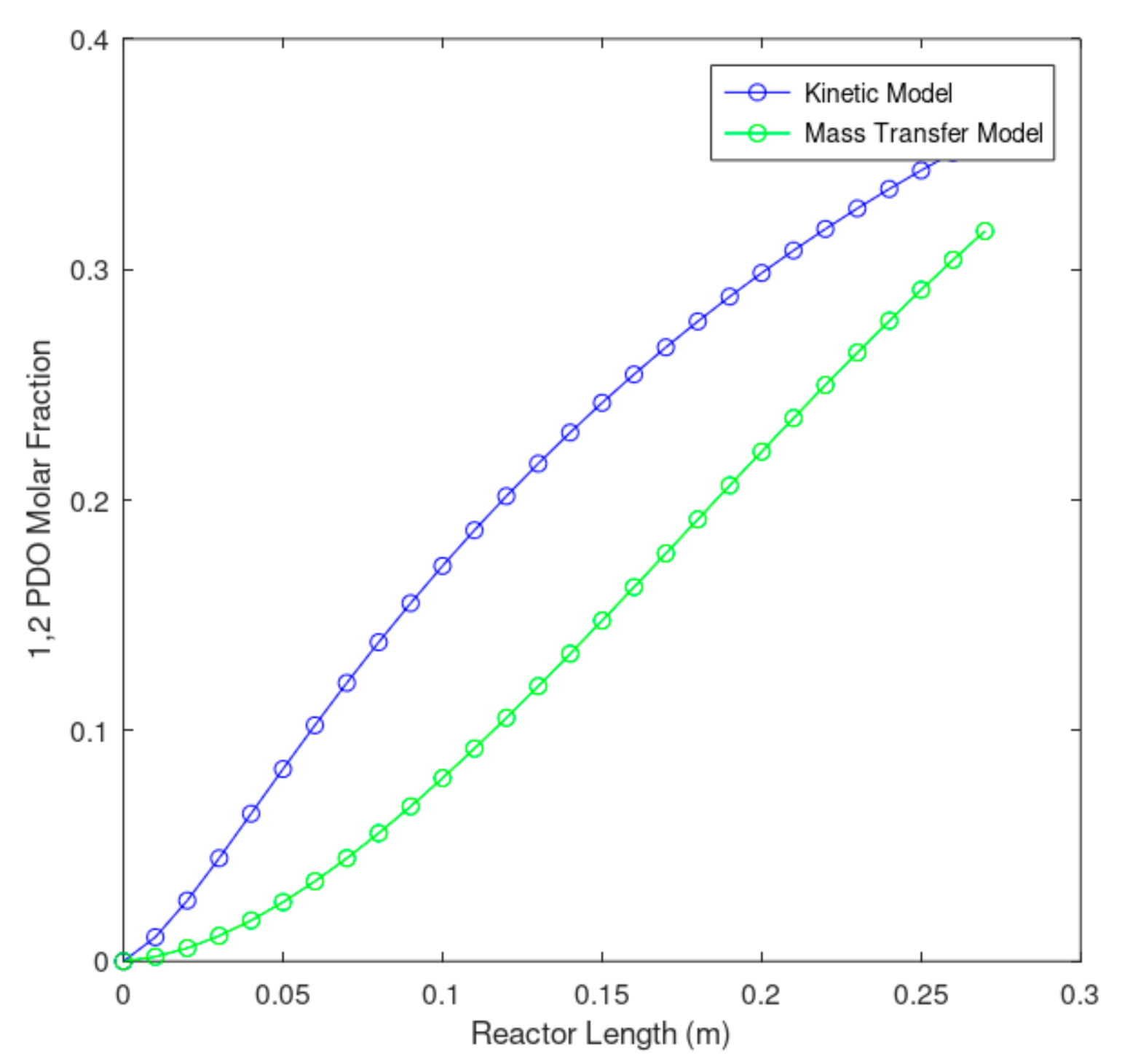
Figure 7 shows the effect of the mass transfer limitations on 1,2 propanediol production. Due to the mass transfer limitations of the liquid phase, the acetol conversion into 1,2 propanediol diminished due to the lack of available hydrogen in the liquid phase, reducing the expected kinetic model catalyst selectivity of 98% toward the 1,2 propanediol to an 80% with the mass transfer model. It is important to note that, due to the lack of more detailed kinetic models, it was not possible to calculate the expected effects or the selectivity toward the other undesired products. The reported selectivity at laboratory scale [
6] for this reaction was 93.4% for 1,2 propanediol, 1.2% for acetol, 2.7% for ethylene glycol, and 2.7% for other compounds, like methanol, ethanol, and propanol.
Figure 8 and
Figure 9 show the hydrogen concentration in the liquid and solid phases. This confirms that the mass transfer in the liquid phase does not directly affect the conversion but affects selectivity. This phenomenon occurs, because the hydrogen concentration in the solid phase (the catalyst) is low, and therefore, this limits the conversion of 1,2 propanediol.
Most of the available literature is based on experimental results [
13,
31,
32], and the correlations are obtained from those experiments; in some cases, the conditions are quite different from actual industrial operations [
33,
34]. In this work, it was possible to select an appropriate and comparable trickle bed reactor to other similar reactors (see
Table 4), whose selected parameters were validated with Al-Dahhan et al. [
31]. This allowed us to evaluate the three main assumptions that allow us to obtain a simpler and more coherent model that permitted the comparison between a kinetically driven model and a mass transfer-driven model: (i) an isothermal operation was achieved by imposing restrictions on the diameter of the reactor (0.0125 m) and particle (0.0008 m), (ii) to exclude the axial direction (undesirable), the criteria proposed by Mears et al. [
35] (see
Table 2) was used to help simplify the mass transfer model, and (iii) the formation of small channels between particles was achieved, fulfilling the criteria indicated in
Table 2 and allowing a more general assumption of a plug flow fixed bed reactor.
4. Conclusions
The reactor behavior was studied considering two different models, a kinetically driven reactor model and a mass transfer driven reactor model. The comparison between both models showed the importance of interfacial and intraparticle transport phenomena in trickle bed reactors, showing that, although the hydrogen is theoretically in excess, the amount that reaches the catalyst through the aqueous phase is low, making the mass transport processes the dominating phenomenon.
By selecting a trickle bed reactor as the most suitable for the catalyst and the reaction conditions, it was possible to identify crucial design and operating parameters that guaranteed near-isothermal operation, low channel formation, and lower axial dispersion, desired conditions for operation at laboratory-scale.
Due to mass transfer limitations, the expected glycerol conversion increased, while the expected 1,2 propanediol selectivity decreased; however, these results remained within the limits reported in the literature, between 75 and 98.2% for most of the catalysts.
Although this work is a theoretical approach to a much-studied experimental phenomenon, such as 1,2 propanediol production through glycerol hydrogenation, adequate catalysts selection is not the only critical factor for the process design.
Since such a strong influence of hydrodynamic and mass transfer parameters has been identified in a simplified mass transfer model, such as the one used in this work, it can be concluded that the actual design of a full-scale reactor would be much more complex and can present lower than expected selectivity and conversions.
Author Contributions
Conceptualization, J.B.R., J.A.B. and A.J.B.; Methodology, J.B.R., J.A.B. and A.J.B.; Software, J.B.R. and J.A.B.; Validation, J.B.R., J.A.B., C.D.P. and A.J.B.; Formal analysis, J.B.R., J.A.B., C.D.P. and A.J.B.; Investigation, J.B.R., J.A.B. and A.J.B.; Resources, A.J.B.; Data curation, J.B.R. and J.A.B.; Writing—Original draft preparation, J.A.B.; Writing—Review and editing, J.B.R., J.A.B. and A.J.B.; Supervision, J.B.R. and J.A.B.; Project administration, A.J.B.; funding acquisition, J.B.R., J.A.B. and A.J.B. All authors have read and agreed to the published version of the manuscript.
Funding
The APC was funded by Universidad del Norte, Barranquilla-Colombia.
Institutional Review Board Statement
Not applicable.
Informed Consent Statement
Not applicable.
Data Availability Statement
Data will be available upon request.
Acknowledgments
Authors would like to thank FUNDACIÓN UNIVERSIDAD DEL NORTE for funding this research.
Conflicts of Interest
The authors declare no conflict of interest.
Nomenclature
| Pressure Drop |
| L | Length |
| Superficial mass velocity of gas |
| Hydraulic diameter |
| Modified Lockhart–Martinelli number |
| Reynolds number of liquid |
| Weber number |
| Particle diameter |
| Liquid kinematic viscosity |
| Gas kinematic viscosity |
| G | Gas mass velocity |
| Galileo number of liquid |
| Gas–liquid mass transfer coefficient |
| Specific gas–liquid interfacial area |
| Gas–liquid diffusivity |
| Schmidt number of liquid |
| Schmidt number of gas |
| Sh | Sherwood number |
| Diffusivity of hydrogen |
| Solubility coefficient of A at equilibrium |
| First reaction rate |
| Second reaction rate |
| First reaction rate constant |
| Second reaction rate constant |
| Absorption rate constant of glycerol |
| Absorption rate constant of acetol |
| Absorption rate constant of hydrogen |
| Absorption rate constant of propylene glycol |
| Molar concentration glycerol |
| Molar concentration acetol |
| Molar concentration propylene glycol |
| Pressure hydrogen |
| Molar flow rate glycerol |
| Molar flow rate propylene glycol |
| Gas density |
| Liquid density |
| Porosity |
| External liquid saturation |
| External contacting efficiency |
| Liquid viscosity |
| Gas viscosity |
| Bed voidage |
References
- Posada, J.; Cardona, C.; Orrego, C. Biodiesel production: Biotechnological approach. Int. Rev. Biophys. Chem. 2009, 1, 571–580. [Google Scholar]
- Ogunkunle, O.; Ahmed, N.A. A review of global current scenario of biodiesel adoption and combustion in vehicular diesel engines. Energy Rep. 2019, 5, 1560–1579. [Google Scholar] [CrossRef]
- Quispe, C.A.; Coronado, C.J.; Carvalho, J.A., Jr. Glycerol: Production, consumption, prices, characterization, and new trends in combustion. Renew. Sustain. Energy Rev. 2013, 27, 475–493. [Google Scholar] [CrossRef]
- Dasari, M.; Kiatsimkul, P.; Sutterlin, W.; Suppes, G. Low-pressure hydrogenolysis of glycerol to propylene glycol. Appl. Catal. A 2004, 281, 225–231. [Google Scholar] [CrossRef]
- Wang, X.; Weng, Y.; Zhao, X.; Xue, X.; Meng, S.; Wang, Z.; Zhang, W.; Duan, P.-G.; Sun, Q.; Zhang, Y. Selective hydrogenolysis and hydrogenation of furfuryl alcohol in the aqueous phase using Ru–Mn-based catalysts. Ind. Eng. Chem. Res. 2020, 59, 17210–17217. [Google Scholar] [CrossRef]
- Zhou, Z.; Li, X.; Zeng, T.; Hong, W.; Cheng, Z.; Yuan, W. Kinetics of hydrogenolysis of glycerol to propylene glycol over Cu-ZnO-Al2O3 catalysts. Chin. J. Chem. Eng. 2010, 18, 384–390. [Google Scholar] [CrossRef]
- Tomishige, K.; Nakagawa, Y.; Tamura, M. Selective hydrogenolysis and hydrogenation using metal catalysts directly modified with metal oxide species. Green Chem. 2017, 19, 2876–2924. [Google Scholar] [CrossRef]
- Mane, R.; Patil, S.; Shirai, M.; Rayalu, S.; Rode, C. Influence of carbon based supports on selectivity behavior of diols and propanol in Ru catalyzed glycerol hydrogenolysis. Appl. Catal. B 2017, 204, 134–146. [Google Scholar] [CrossRef]
- Kuroaka, T.; Maruyama, H.; Naribayashi, I.; Sasaki, Y. Production of 1,3-propanediol by hydrogenolysis of glycerol catalyzed by Pt/WO3/ZrO2. Catal. Commun. 2008, 9, 1360–1363. [Google Scholar] [CrossRef]
- Shariff, H.; Al-Dahhan, M.H. Analyzing the impact of implementing different approaches of the approximation of the catalyst effectiveness factor on the prediction of the performance of trickle bed reactors. Catal. Today 2020, 353, 134–145. [Google Scholar] [CrossRef]
- Jarullah, A.; Mujtaba, I.; Wood, A. Kinetic parameter estimation and simulation of trickle bed reactor for hydrodesulfurization process in small trickle bed reactor. Chem. Eng. J. 2005, 105–110. [Google Scholar] [CrossRef]
- Seretic-Bionda, K.; Gomzi, Z.; Saric, T. Testing of hydrodesulfurization process in small trickle bed reactor. Chem. Eng. J. 2005, 106, 105–110. [Google Scholar] [CrossRef]
- Ranade, V.; Chaudhari, R.; Gunjal, P. Trickle bed reactors. React. Eng. Appl. 2011, 284. [Google Scholar] [CrossRef]
- Sang, L.; Tu, J.; Cheng, H.; Luo, G.; Zhang, J. Hydrodynamics and mass transfer of gas–liquid flow in micropacked bed reactors with metal foam packing. AIChE J. 2020, 66, e16803. [Google Scholar] [CrossRef]
- Ellman, M.; Midoux, N.; Wild, G.; Laurent, A.; Charpentier, J. A new improved liquid hold-up correlation for trickle bed reactors. Chem. Eng. Sci. 1990, 45, 1677–1684. [Google Scholar] [CrossRef]
- Holub, R.; Dudukovic, M.; Ramachandran, P. A Phenomenological model for pressure drop, liquid hold-up and flow regime transition in gas-liquid trickle flow. Chem. Eng. Sci. 1992, 47, 2343–2348. [Google Scholar] [CrossRef]
- Al-Dahhan, M.; Dudukovic, M. Pressure drop and liquid hold-up in high pressure trickle bed reactors. Chem. Eng. Sci. 1994, 49, 5681–5698. [Google Scholar] [CrossRef]
- Iliuta, I.; Larachi, F.; Grandjean, B.; Wild, G. Gas-liquid interfacial mass transfer in trickle bed reactors: State-of-the-art correlations. Chem. Eng. Sci. 1999, 54, 5633–5645. [Google Scholar] [CrossRef]
- Iliuta, I.; Thyrion, F. Gas-liquid mass-transfer in fixed beds with two-phase co-current downflow: Gas/Newtonian and non-Newtonian liquid systems. Chem. Eng. Technol. 2004, 538–549. [Google Scholar] [CrossRef]
- Wild, G.; Larachi, F.; Charpentier, J. Heat and Mass Transfer in Gas-Liquid-Solid Fixed Bed Reactors; Elsevier: Amsterdam, The Netherlands, 1992. [Google Scholar]
- Zhang, J.; Teixeira, A.R.; Jensen, K.F. Automated measurements of gas-liquid mass transfer in micropacked bed reactors. AIChE J. 2018, 64, 564–570. [Google Scholar] [CrossRef]
- Chou, T.; Worley, J.; Luss, D. Local particle-liquid mass transfer fluctuations in mixed-phase co-current downflow through a fixed bed in the pulsing regime. Ind. Eng. Chem. Fundam. 1979, 18, 279–283. [Google Scholar] [CrossRef]
- Hirose, T.; Mori, Y.; Sato, Y. Liquid-to-particle mass transfer in fixed bed reactor with co-current gas-liquid downflow. J. Chem. Eng. Jpn. 1976, 9, 220–225. [Google Scholar] [CrossRef] [Green Version]
- Kawase, Y.; Ulbretch, J. Newtonian fluid sphere with rigid or mobile interface in a shear-thinning liquid: Drag and mass transfer. Chem. Eng. Commun. 1981, 8, 213–231. [Google Scholar] [CrossRef]
- Dwivedi, P.; Upadhyah, S. Particle fluid mass transfer in fixed and fluidized beds. Ind. Eng. Chem. Process Des. Dev. 1977, 16, 157–165. [Google Scholar] [CrossRef]
- Gaetan, M.; Jamal, C.; Francis, L. Trickle bed laboratory reactors for kinetic studies. Int. J. Chem. React. Eng. 2009, 7, 1–70. [Google Scholar] [CrossRef]
- Xi, Y.; Holladay, J.; Frye, J.; Oberg, A.; Jackson, J.; Miller, D. A kinetic and mass transfer model for glycerol hydrogenolysis in a trickle bed reactor. Org. Process Res. Dev. 2010, 14, 1304–1312. [Google Scholar] [CrossRef]
- Pandey, D.; Biswas, P. Continuous production of propylene glycol (1,2-propanediol) by the hydrogenolysis of glycerol over a bi-functional Cu–Ru/MgO catalyst. React. Chem. Eng. 2020, 5, 2221–2235. [Google Scholar] [CrossRef]
- Zhao, H.; Zheng, L.; Li, X.; Chen, P.; Hou, Z. Hydrogenolysis of glycerol to 1,2-propanediol over Cu-based catalysts: A short review. Catal. Today 2020, 355, 84–95. [Google Scholar] [CrossRef]
- Sepulveda, J.; Manuale, D.; Santiago, L.; Carrara, N.; Torres, G.; Vera, C.; Goncalves, M.; Carvalho, W.; Mandelli, D. Selective hydrogenolysis of glycerol to propylene glycol in a continuous flow trickle bed reactor using copper chromite and Cu/Al2O3 catalysts. Química Nova 2017, 40, 371–377. [Google Scholar] [CrossRef]
- Al-Dahhan, M.; Larachi, F.; Dudukovic, M.; Laurent, A. High-pressure trickle-bed reactors: A review. Ind. Eng. Chem. Res. 1997, 36, 3292–3314. [Google Scholar] [CrossRef]
- Bittante, A.; García-Serna, J.; Biasi, P.; Sobrón, F.; Salmi, T. Residence time and axial dispersion of liquids in Trickle Bed Reactors at laboratory scale. Chem. Eng. J. 2014, 250, 99–111. [Google Scholar] [CrossRef]
- Kawatra, P.; Panyaram, S.; Wilhite, B. Hydrodynamics in a pilot-scale concurrent trickle-bed reactor at low gas velocities. AIChE J. 2018, 64, 2560–2569. [Google Scholar] [CrossRef]
- Al-Dahhan, M.; Dudukovic, M. Catalyst bed dilution for improving catalyst wetting in laboratory trickle-bed reactors. AIChE J. 1996, 42, 2594–2606. [Google Scholar] [CrossRef]
- Mears, D. Diagnostic criteria for heat transport limitations in fixed bed reactors. J. Catal. 1971, 20, 127–131. [Google Scholar] [CrossRef]
- Sie, S.; Krishna, R. Process development and scale up: III. Scale-up and scale-down of trickle bed processes. Rev. Chem. Eng. 1998, 14. [Google Scholar] [CrossRef]
| Publisher’s Note: MDPI stays neutral with regard to jurisdictional claims in published maps and institutional affiliations. |
© 2021 by the authors. Licensee MDPI, Basel, Switzerland. This article is an open access article distributed under the terms and conditions of the Creative Commons Attribution (CC BY) license (http://creativecommons.org/licenses/by/4.0/).


