1. Introduction
According to statistics, electric motors consume 46 percent of the world’s electricity and account for nearly 70% of the net consumption of industrial energy [
1]. Power consumption by pump systems alone accounts for about 22% of the world’s energy out of which centrifugal pumps consume 16% [
2]. Centrifugal pumps have tremendous energy consumption and substantial potential for energy savings. Therefore, researching the possibilities of increasing the efficiency of pump units are need of the hour.
Multistage centrifugal pumps are capable of increasing liquid pressure and pump fluids to a large distance and are widely used in field irrigation, urban afforestation, groundwater supply, and chemical and petroleum industries. Among them, the double-suction centrifugal pumps can achieve twice the flow rate of a single-suction pump with the same diameter and have better cavitation performance [
3]. A double-suction multistage centrifugal pump requires a great deal of energy for the year-round operation and achieving an energy-efficient design can save cost and improve the overall pump performance.
A double-suction multistage centrifugal pump was designed for specific applications in the petrochemical processing plants. The design feasibility study of the pump showed effectiveness in handling multiple fluids without performance degradation [
4]. In our previous study [
5], the hydraulic loss analysis of the pump revealed vast potentiality in stage-wise performance recovery specifically at the second stage. The losses were mostly associated with large radial forces in the fluid passing from Stage 1 to 2 through a twin volute. The high circumferential velocity of the fluid at the interface between Stages 1 and 2 caused excessive pre-swirl at the second stage impeller inlet. The fluid pre-swirl induced losses at the second stage impeller thereby decreasing the pump efficiency. Certain design recommendations were provided to control the pre-swirl and enhance the pump characteristics. The recommendation to use a guide vane between the first and second stages is presented in this paper.
Inlet guide vane installation is a common technique to control the fluid circulation and pressure ratio at the inlet of a turbomachine. This method was initially carried out in compressors and fans and was recently applied to centrifugal pumps to regulate fluid pre-swirl at the inlet [
6]. Tan et al. [
7] studied the effect of an adjustable inlet guide vane for the pre-swirl regulation of a single-stage centrifugal pump and obtained a higher efficiency and head at the design point at an angle of 24°. Yuchuan et al. [
8] studied the same IGV for angles ±36° and ±60° to find the influence of guide vanes on unsteady flow. Qu et al. [
9] studied the clocking effect of the same IGV and found little influence on pump performance. Liu et al. [
10] compared the performance between a 2D IGV and a 3D IGV with a similar design and obtained a higher efficiency with a minimum impact velocity moment for the 3D IGV model. Further investigation by Liu et al. [
11] succeeded in suppressing the losses associated with high pressure near the impeller inlet and facilitated a uniform distribution of pressure in the impeller channels at the rotational frequency. Liu et al. [
12] studied the influence of the IGV angle and axial distance range between IGV and impeller. The IGV angle had a significant impact in reducing the pressure fluctuation at the blade leading edge while the axial distance had only a slight impact on the pump performance. Lin et al. [
13] used an adjustable two plate inlet guide vane at the suction pipe of a single-stage centrifugal pump to reduce the negative pressure at the impeller leading edge. The pump performance was improved at a vane angle of 25°, weakening the vortex flow at the pump inlet. Hou et al. [
14] studied the effect of the number of IGV vanes on the hydraulic characteristics and suggested a six-vane design for a higher head and better efficiency. It is evident from the literature that an IGV is capable of regulating the pre-swirl at the impeller inlet. However, all these IGV configurations were applied to regulate the pre-swirl in single-stage pumps with an option to control the IGV angle. This is not the case with multistage centrifugal pumps. The usage of pre-swirl regulation of IGV is extremely rare for multistage pumps simply due to the physical constraint to control the IGV angle using gears or levers during operation. Typically, radial diffusers and return guide vanes of fixed angles are used in multistage pumps to transfer fluid from one stage to another. However, a radial diffuser-return vane combination cannot be used to regulate the axial flow exiting the twin volute of the proposed pump. An axial diffuser or a guide vane with a fixed angle is the technically feasible unit that can be installed to regulate this flow.
In order to govern the pre-swirl of the flow between the volute and the second stage impeller, the stationary guide vane design must be meticulously configured since the vane angle is not adjustable. An inducer type, a screw-type, or a helico-axial design is selected for this purpose since the twisted vane design can convert the rotational inertia of the fluid to axial momentum without the need to adjust the angle. Several inducer type pump designs can be found in the literature. Li et al. [
15] studied the flow through a three-blade inducer on an axial flow pump and found that the maximum pressure is generated when the inducer angle is aligned with the impeller such that the wake from the inducer impinges the impeller blade minimizing hydraulic losses. Campos-Amezcua et al. [
16] studied a two-blade inducer design in a turbo-pump with and without clearance and observed that a uniform axial velocity profile is obtained for an inducer without clearance. Yang et al. [
17] studied the clocking effect between the inducer and impeller in a high-speed centrifugal pump and obtained the best performance when the relative angle between the inducer trailing edge and impeller leading edge was 0°. Several pump designers used inducers at the upstream of the impeller to reduce pump cavitation [
18,
19,
20,
21,
22]. Although inducers were used in centrifugal pumps for decades, they are not commonly found in multistage centrifugal pumps. Sedlár et al. [
23] installed a three-bladed inducer in a two-stage centrifugal pump between the inlet guide vane and the first stage impeller. The pump with an inducer showed better cavitation reduction than the pump without an inducer. From these works of literature, it can be said that the application of inducers in centrifugal pumps showed great potential in improving the performance and decreasing the cavitation phenomena. However, all the inducers mentioned are rotating devices with the same speed as the impeller. Since a stationary guide vane is the requirement of the proposed pump, the number of vanes and other design configurations of the inducer shape is influenced by the literature to create an inducer-type guide vane. The ITGV design specifications are provided in the next section.
A multistage centrifugal pump design with an ITGV device to minimize the hydraulic losses occurring at the inter-stage flow passage between the twin volute and second-stage impeller is presented in this paper. The effect of the ITGV design on the overall performance of the pump and the dynamics of the fluid passing through the ITGV is explained in detail.
2. Design Configurations
The centrifugal pump is designed to pump fluids used in petrochemical refineries satisfying high-head and high-flow rate requirements. The number of stages, the impeller dimensions and other design parameters are determined by API BB5 centrifugal pump standards [
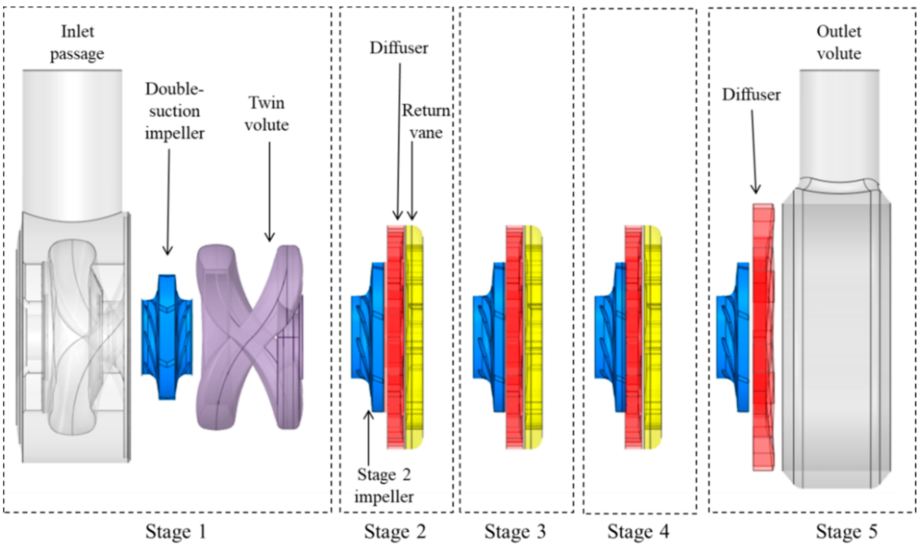
24]. The initial pump model is obtained from a dynamically similar scaled-down pump model used for low flow rate operations. The multistage centrifugal pump consists of an inlet passage, a double-suction impeller and a twin-volute in the first stage. Stages 2–4 have a single-suction impeller, a stationary diffuser and return guide vanes. The fifth stage consists of the impeller, diffuser, and outlet volute.
Figure 1 shows the exploded view of the pump components.
The theoretical performance curve of the pump is obtained from the pump affinity laws as shown below:
where
Q,
H,
P, and n represents the flow rate, head, input power and rotational velocity, respectively. The subscripts 1 and 2 correspond to the model and the prototype.
Water is chosen as the working fluid for the simulations as the pump affinity laws apply only for water or pure liquids with kinematic viscosity less than 10 cS [
25]. The five-stage centrifugal pump has a flow coefficient of ∅ = 0.01 and head coefficient
= 0.67. The impellers at stages 2–5 have a diameter 20% larger than the first stage impeller. The fifth stage diffuser is 16% larger in diameter than the diffusers in stages 2–4. The twin-volute is staggered at 180° to each other to balance out the radial forces. The impellers contain seven blades while the diffuser and return vane consist of eight vanes.
The flow coefficient, the head coefficient and efficiency are calculated using the following equations:
where
D,
g,
η, and
ρ corresponds to the diameter of the impeller, acceleration due to gravity, the efficiency and the density of the fluid, respectively.
A stationary inducer-type guide vane is installed between the first and the second stage with a length of 0.27D. The ITGV consists of three blades shrouded to the casing without clearance. The preliminary design is inspired by a helico-axial impeller designed and optimized in our laboratory [
26,
27,
28]. The design thus obtained is modified to suit the pump dimensions. The ITGV inlet is designed symmetrically with the fluid which exits the volute being with perfect hydraulic symmetry at all flow conditions. The exit blade angle is matched with the second stage impeller inlet blade angle. The shroud diameter of the ITGV is chosen to be the same as the second stage impeller diameter while the hub diameter is equal to the diameter of the pump shaft. The thickness is maintained equally throughout the blade length.
Figure 2 shows the 3D ITGV CAD model and the overall pump design with ITGV.
3. Numerical Model
Three-dimensional mass and momentum equations are solved in a commercial CFD solver to study the flow behavior inside the pump. The fluid transportation equations are based on the steady incompressible Reynolds-averaged Navier–Stokes (RANS) equations solved using an iterative approach in ANSYS CFX 19.1® software (ANSYS, Inc., Pennsylvania, PA, USA). These equations are very well documented in numerous literature [
29,
30,
31]. The turbulence model, k–ω based shear stress transport (SST) is used to predict the turbulence occurring inside the pump. The SST model uses an integrated feature to shift from a high Reynold’s number form of the k–ε model away from the boundary layer and the k–ω model near the wall region [
32]. A blending function is used to ensure a smooth transition between the models. Similar studies by the authors using the SST model are well proved to predict the turbulent behavior in a three-stage centrifugal pump [
33,
34].
The 3D design of the impeller blades, ITGV blades, diffuser and return channel vanes are generated using ANSYS Bladegen® tools (ANSYS, Inc. Pennsylvania, PA, USA) while the inlet passage, the twin-volute and the outlet volute are designed using CAD software. The fluid domains are extracted using ANSYS SpaceClaim® module (ANSYS, Inc. Pennsylvania, PA, USA)while ANSYS meshing tool is used for the grid generation. The impeller domain grids are created using ANSYS TurboGrid® software (ANSYS, Inc. Pennsylvania, PA, USA)which provides an exceptional level of mesh quality with preferred boundary layer resolution. The CFD model including the boundary conditions for the numerical analysis was prepared using CFX-Pre. The governing equations were solved in CFX-Solver and the post-processing was done in CFX-Post.
Figure 3a shows the CFD domain used for the pump without the ITGV component. Due to the periodic nature of the geometry; the impellers, diffuser, and return channel domains are chosen as a single passage to save computational resources without compromising on the accuracy of the results. The impeller domains are rotating along the rotational axis while all other domains remain stationary. The outlet pipe is extended to avoid any unlikely backflow occurring at the outlet. The working fluid is water. Atmospheric pressure condition and mass flow rate is defined at the inlet and outlet, respectively. Since the pitch ratio is high at the interface between the stationary domains and rotating domains, the mixing-plane (stage) interface model is applied for the steady-state simulations. General Grid Interface (GGI) mesh connection is provided at all the interfaces to connect the non-conformal elements between the domains. The GGI determines the connectivity between the grids on either side of the interface using an intersection algorithm [
35]. The convergence criterion for the RMS residual target was set at 1 × 10
6. Due to the complexity of the multistage pump geometry, the convergence was ensured by monitoring important variables such as the flow rate at the pump outlet, the torque at the impeller blades and the head generated by the pressure gradient at all timesteps. A reasonable convergence was obtained for all the simulations.
Overview of Grid Generation
The simulation-based study requires a grid independency test to ensure that the results obtained do not vary with grid size. Due to the complexity of the multistage centrifugal pump, the grid study was carried out separately for stages 1 and 2. The optimum grids thus obtained would satisfy the entire pump model since the other stages are a replication of the second stage. The grid number for the outlet volute in the fifth stage is generated analogously to the first stage inlet passage. Since the simulations for the grid independency tests are carried out in two stages, the boundary domains of the individual stages are extended to avoid possible backflow in the simulations. The generated grids are shown in
Figure 3b. To resolve the boundary layers, multiple layers of hexahedral meshes are stationed along the blade suction and pressure side surfaces for the impeller, diffuser, and return vanes. The y+ values at these boundaries are kept below 30 while they are maintained below 100 at other locations.
The grid convergence index (
GCI), derived based on the Richardson extrapolation method, is the most reliable method for a grid convergence study [
36]. An approximate relative error (
ea) and fine grid convergence index (
GCIfine) is calculated for a key variable obtained from three different sets of grids with significant resolutions. The efficiency of the centrifugal pump is taken as the key variables in this study. The grid convergence index can be calculated from:
where
r is the grid refinement factor.
The GCIfine for stage 1 and stage 2 were obtained as 0.6% and 0.91%, respectively. Since the efficiency obtained for the fine grid has GCI value of less than 1%, it can be said that the generated grids are optimum and further grid refinement is not necessary. The number of nodes for the optimum grid was 1.75 and 1.35 million for stages 1 and 2, respectively. The total number of nodes generated to create the entire pump domain was 6.25 million. Based on the optimum grid, the grid for the ITGV domain was generated with almost the same number of nodes as the impeller blades. Therefore, further grid study with the ITGV pump is unnecessary.
4. Pump Performance
The performance of the pump design obtained from the affinity laws are firstly calculated theoretically and then numerically using CFD tools. The overall pump performance curve obtained by the theoretical calculation is compared with the CFD results in
Figure 4. The head coefficient, flow coefficient and efficiency are normalized by their corresponding design point values. The predicted trend of the head and efficiency curves along the change of flow has concurred with the theoretical prediction. The curves obtained from the CFD simulations are in reasonable agreement with the theoretical calculations with an error percentage of less than 8%. The calculation accuracy has a certain influence because of the limitations of the steady-state simulation, the simplified geometrical model and overlooking of losses in the CFD simulation. Since this is a preliminary design feasibility study prior to experimental analysis without considering the unaccounted mechanical losses, the obtained CFD results are acceptable for further analysis.
The overall performance of the pump with and without ITGV is compared in
Figure 5. The efficiency of the pump remains unaffected in the low flow rate condition while the head increases slightly due to a minor increase in pressure gradient at the ITGV. At the best efficiency point (BEP), the efficiency has increased by 3.94% while the head increased by 5.78%. The overall performance of the pump has increased by a great margin with the installation of ITGV. The improvement in the pump performance, however, comes at a cost of increased power consumption. The power consumption increased by 1.78% at the BEP and by 8.85% at the maximum flow rate condition with the installation of ITGV. The increase in power consumption is not high at the BEP point at which the pump would be operated normally, and it is high at the maximum flow rate, which is seldom operated. Even with the rise in power consumption at the maximum flow rate condition, the increase in efficiency and head is large enough to offset the difference.
The performance study of the individual stages is as important as the overall performance in a multistage centrifugal pump. The stage-wise efficiency and head coefficient curves of the two pumps are presented in
Figure 6. The efficiency at the low flow rate is almost the same at all stages for the pump with and without ITGV. As the flow rate increases, the hydraulic efficiency improves for all stages except for stage 2. The efficiency at stage 2 descends at high rates beyond BEP for the reference pump. Similarly, the head coefficient drops near 0.1 at the maximum flow rate. The large drop in efficiency and head of the reference pump indicates a very large loss at the second stage. The pump with ITGV has improved the efficiency by 47.17% and head by 63.28% at the design point of stage 2. A similar increase is also observed at the maximum flow rate condition of stage 2. The small improvement in the parameters can be found in other stages as well. Installing the IGTV has thus not only improved the performance of stage 2 by a great margin but also improved the performance at all stages. This increase in efficiency and head at all stages reflects the overall improvement in the pump performance as found in
Figure 5.
A detailed analysis of the losses observed at stage 2 and the influence of the ITGV in mitigating these losses must be studied in-depth to understand the flow physics at the ITGV-Impeller interface. The pump is operated at the design point more often than others and as a reason; the pump operating at the design point is chosen for the in-depth analysis. The second stage consists of the impeller, diffuser and return vanes. The losses are mostly observed at the inlet of the impeller and, thus, the loss analysis is focused on the flow through the ITGV and second stage impeller only. Henceforth, the term ‘impeller’ refers to the second stage impeller unless stated otherwise.
The blade loading at the mid-span of the impeller along the streamwise direction of the pump with and without ITGV is shown in
Figure 7. The pressure is normalized by its maximum value. A large drop in pressure at the leading edge is observed in the reference pump indicating the location of the maximum loss. Such sharp pressure drops may cause the formation of cavitation bubbles and can easily lead to pump failure. The installation of the ITGV device at the upstream of the impeller has decreased the pressure drop by 66.13% at the leading edge of the impeller. The overall blade loading has improved significantly by a weighted average of 35.6% with the installation of the ITGV. The weighted average is calculated to accurately represent the average of the percentage change in quantity. The ITGV not only has an impact on the stage 2 impeller but also on the downstream impellers. The blade loading of impellers at stages 3, 4, and 5 (not shown here) was also improved by a weighted average of 17.96%, 10.32%, and 7.09%, respectively.
The significance of improvement in the blade loading is explained by its effect on individual stages. The head and efficiency trend graph along the mid-span of the impellers for stages 2–5 at the design point is plotted in
Figure 8. The parameters are normalized by the corresponding maximum values of the reference pump. Since the ITGV does not affect the upstream flow, the trend line is not plotted for stage 1. A head drop is observed at the second stage of the reference pump at about 20% of the streamwise direction. This corresponds to the pressure drop observed in
Figure 7 at 0.2 streamwise. The head rises again towards the trailing edge of the impeller. The head increases at each stage and finally achieves the maximum head at the end of the 5th stage. The ITGV has prevented the drop in pressure gradient at the 2nd stage, which resulted in an increase of head at this stage and an overall increase in the consecutive stages. The overall head trend graph increased by a weighted average of 17.87% with ITGV compared to the reference pump.
The efficiency trend graph shows the rise in efficiency at each stage. At the beginning of each stage, the dive in the efficiency curve is due to the abrupt change in the pressure gradient as the fluid travels from one stage to another. While the efficiency dives at each impeller’s leading-edge, it immediately climbs back up and rises sharply at the trailing edge. However, the efficiency remains the lowest at the second stage of the reference pump due to the losses mentioned earlier. The introduction of ITGV has aided in reducing the losses and improving the efficiency at the second stage as well as an overall increase in the consecutive stages. The weighted average increase in the overall efficiency trend graph is 14.48% compared to the pump without ITGV. The potential of the ITGV is remarkable in improving the pump characteristics. However, how the ITGV design affects the fluid flow behavior and the reason for losses and the effects of ITGV are studied qualitatively in the next section.
5. Flow Field Analysis
The fluid flowing through the volute, ITGV and the second stage impeller is analyzed in detail to determine the causes for the losses and the correction by the ITGV at the design point. From the first stage impeller, the fluid entering the volute splits into the two arms of the 180° staggered twin-volute, flows along the surfaces of the volute and joins back towards the exit of the volute. The fluid is found to have a greater radial force than the axial force at the volute exit and, as a result, produces a pre-swirl at the inlet of the second stage impeller. This high-intensity swirl flow causes deviation between the fluid incidence angle and blade angle at the impeller leading edge. The flow through the volute and the impeller is shown in
Figure 9a. The 3D velocity streamlines show a shift in the flow direction due to the fluid moving from a stationary domain to a rotating domain. However, the flow direction entering the impeller flows away from the blade incidence angle due to the high swirl intensity. The absolute velocity increases at the impeller inlet due to the large circumferential velocity at the volute exit. This causes flow separation at the leading edge and gives rise to recirculation regions at the inlet and the pressure side of the impeller, leading to the formation of vortices in the flow. The vortex core region formed at the impeller is shown in
Figure 9b. The vortices thus formed cause blockage to the incoming flow thereby decreasing the pressure at this region. The pressure drop directly affects the stage performance and result in losses at the second stage impeller.
The installation of the ITGV does not prevent the formation of the high-intensity swirl flow observed at the exit of the twin-volute; it rather continues the flow along the ITGV blades without changing its direction. The magnitude of the velocity decreases as the fluid flows through the stationary blades of the ITGV as shown in
Figure 10a. The average velocity of the fluid decreased from 33.86 m/s at the volute exit to 22.65 m/s at the ITGV exit. The decrease in circumferential velocity at the exit of the ITGV allows the fluid to flow towards the incidence angle of the blade leading edge. This is because the ITGV exit blade angle is configured to match the impeller inlet blade angle. As a result, the flow separation at the impeller leading edge is moderated and thereby decrease the intensity of the vortices formed at the impeller.
Figure 10b shows the decrease in vortex core in the second stage impeller. The blockage in the flow is removed with the installation of ITGV and hence the pressure losses are diminished.
The flow angles are explained in detail by plotting the velocity diagram at the leading edge of the impeller in
Figure 11. The vectors U and C
U represent the blade velocity and the tangential velocity, respectively. In
Figure 11a, the relative flow angle is
β = 128.5° while the absolute flow angle is
α = 11.86° at the inlet of the impeller for pump without ITGV. The large relative flow angle force the fluid to flow virtually perpendicular to the blade. The relative flow angle decreases sharply to
β = 56.4° and the absolute flow angle rises to
α = 17.6° for the pump with ITGV as shown in
Figure 11b. The magnitude of the relative velocity (W) remains essentially the same while the direction changes towards the blade angle similar to the observation in
Figure 10a. The magnitude of the absolute velocity (C) decreases by 22.46%. The velocity triangles of the rest of the stages are approximately the same for both pumps.
The relative flow angle correction achieved by the ITGV has a significant impact on the fluid inside the impeller. The velocity streamlines at the mid-span of the impeller is compared in
Figure 12a,b. There is an adverse pressure gradient between the blades leading to the formation of the vortex and a non-uniform flow is observed at the reference pump. The flow through the impellers appears to be smooth and uniform with the disappearance of vortices in the pump with ITGV. The total pressure in stationary frame contour is shown in
Figure 12c,d. The low-pressure region at the pressure-side of the blades is eliminated to obtain a smooth transition of fluid pressure from the inlet to the outlet of the ITGV pump impeller. The increasing pressure increases the head developed at this stage as observed earlier.
6. Performance Analysis at Off-Design Conditions
The centrifugal pump is generally operated at its design point (Q
d) at which the efficiency curve reaches its maximum. However, the pump may be operated at off-design points at times by force of circumstances to deliver fluid either below or above the capacity at BEP. An adverse pressure gradient, flow separation, and flow recirculation at the inlet and exit always occurs under off-design points. The flow phenomenon is more complex than the design point, especially at the high flow rate conditions. Therefore, it is necessary to study the pump performance at these conditions too. Two off-design conditions are tested at 25% below and excess flow capacity of the design point. The head trend line is compared for low flow rate and high flow rate for both the pumps in
Figure 13a,b. There is a minor increase in the head trend line of the pump with ITGV at 0.75Q
d and a significant increase at the 1.25Q
d flow condition. The head increases by a weighted average of 3.58% at the low flow rate and gains a weighted average of 20.48% at the high flow rate condition for the ITGV pump. A similar increase of weighted average head by 17.87% was observed previously at the design point, too. The losses inside the pump escalate as the flow rate rises but the ITGV is capable of executing head loss correction at all flow rates.
The efficiency trend graph measured at the mid-span of the impellers at both flow rates is compared for the two pumps in
Figure 13c,d. A notable improvement in efficiency is found at the second stage of 0.75Q
d for the ITGV pump while there is only a slight improvement at other stages. Meanwhile, there is no significant improvement in efficiency at the leading edge of the second stage impeller at 1.25Q
d for the pump with ITGV, but it rises near the trailing edge. The rise in efficiency continues for stages 3–5. The ITGV installation improved the overall efficiency of the stages by a weighted average of 13.7% and 18.45% at 0.75Q
d and 1.25 Q
d, respectively. This also proves that correcting the losses at the second stage improves the performance at other downstream stages too. This can be analyzed by plotting the blade loading curve at the mid-span of the second stage impeller along the streamwise direction as shown in
Figure 13e,f. The blade loading distribution was improved by a weighted average of 24.9% and 37.6% at 0.75Q
d and 1.25Q
d, respectively, for the pump with ITGV. Even though the pressure-drop at the leading edge of the impeller decreased by 41% at the high flow rate of the ITGV pump, the pressure is still low enough to cause cavitation damage in the long run. A detailed cavitation analysis may be necessary to find the cavitation zones in the off-design points.
The vortex core region formed near the second stage impeller has practically disappeared with the installation of ITGV at the 0.75Q
d flow condition as shown in
Figure 14a,b. Several large and small vortices are observed at the high flow rate condition near the impeller inlet (
Figure 14c). The large vortices are formed due to huge flow separation at the leading edge which increases with the flow rate. The ITGV pump has diminished the large vortices formed at the blade suction side and decreased the intensity of the vortices formed at the pressure side of the impeller (
Figure 14d). Further suppression of the vortices may be achieved after a design optimization strategy applied to optimize the ITGV and impeller shapes with an objective function to minimize leakage vortices and improve the pump performance at this particular flow condition.
The installation of ITGV has aided in improving the pump efficiency and head at various flow rates. The losses associated with the twin-volute and the second stage blades have been successfully diminished by placing the ITGV between them. However, the ITGV installation comes with certain restrictions. Firstly, the ITGV installation expanded the pump size by 0.27D. This may come as a drawback at locations with size restrictions for a multistage centrifugal pump. Secondly, manufacturing the ITGV unit requires precision machining tools and skilled operators which may induce additional cost to the pump manufacturer. This is determined in the economic analysis and feasibility study of the pump in the manufacturing stage.


 ,
, 
