Article

Electrothermal Desiccant Regeneration Technique for Air Dehumidification

Green Energy and Environment Research Laboratories, Industrial Technology Research Institute, Hsinchu 310401, Taiwan
*
Author to whom correspondence should be addressed.
Processes 2021, 9(7), 1082; https://doi.org/10.3390/pr9071082
Submission received: 29 May 2021 / Revised: 18 June 2021 / Accepted: 20 June 2021 / Published: 22 June 2021
(This article belongs to the Section Manufacturing Processes and Systems)

Abstract

:
Adsorption dehumidification and drying equipment is essential general equipment for domestic and industrial use. The most commonly used type in industry is the compressed air adsorption dryer. The analysis results show that the heat loss of the traditional heat air regeneration system of the compressor dryer is 39.4%, and the exhaust waste heat is 32.4%. The actual use of heat energy for desiccant regeneration is only 28.2%. Therefore, this study uses an innovative electrothermal adsorbent unit (ETAU) to regenerate the desiccant. By directly heating the adsorbent, heat loss can be effectively improved. On the other hand, the composite arrangement of zeolite and activated alumina is used. The inlet compressed air is firstly treated by the activated alumina, which has a high adsorption capacity in the high relative humidity condition, then a zeolite is used as a second part to make the dew point reach –40 °C. In the regeneration step, the airflow direction is reversed, whereby the zeolite is regenerated by the ETAU, and the waste heat of the exhaust air is used to regenerate the activated alumina, which reduces the temperature of the exhaust air. Compared with the traditional heat air compressed air system, the two technologies can save about 27% energy in total.

1. Introduction

Dry compressed air, one of the four primary dynamic sources in industrial plants, is used for various industrial applications, such as in high-tech cleaning processes, drying and cleanliness control, car panel beating and painting processes, food manufacturing, pharmaceutical manufacturing, and energy storage [1,2,3,4]. These applications require high-quality and low-moisture dry compressed air with a dew point in the −20 °C to −70 °C range to maintain process stability and prevent corrosion. Therefore, the process of drying compressed air is essential. In the refrigeration dehumidification method, the operating temperature cannot be less than 0 °C; hence, an adsorption dehumidification method unaffected by temperature constraints is necessary for compressed air drying processes. For example, Yin et al. [5] and Senanayake et al. [6] have used a pressurized liquid desiccant and activated carbon, respectively, to dehumidify compressed air. A new type of desiccant, called metal-organic framework (MOF), was also used by Guo et al. [7] in compressed air dryers. However, all desiccants tend to saturate after adsorption, and therefore air with low relative humidity [8] or high temperature [9] must generally be used to regenerate adsorbents.
A typical heatless compressed air dryer extracts 30–50% dry compressed air from a compressed air system outlet. It drops to atmospheric pressure, creating an environment with a low relative humidity that regenerates desiccants. This process entails very a high energy consumption (approximately 2.0 kW/CMMcompressed air). Heated-air regeneration methods, compared with heatless dryers, enhance the regeneration efficiency of desiccants and divide them into two major types: regenerated source switching [10] and desiccant switching (e.g., desiccant wheel [11] and fluidized bed methods [12]). The regeneration procedure principle of the compressed air dryer and the atmospheric dryer is the same. In both heated-air regeneration types, the air must first be heated, following which the heated air is used to heat the adsorbents. Such indirect heating methods entail excessive heat losses. Figure 1 shows the energy analysis of the traditional compressed air dryer by the Industrial Technology Research Institute in Taiwan. Only 28.2% of the heat was used for adsorbent regeneration. The pipe and container heat loss of the heated-air-flow compressed air dryer was approximately 39.4%. Moreover, because of the pressure drop and nonuniform distribution in the adsorbent packed-bed, overheating (to 200 °C) was necessary to ensure that each portion of the packed-bed could achieve the regeneration temperature of 140 °C (the desiccant is zeolite). Therefore, the heat waste was as high as 32.4%. The heat loss and the heat waste of exhaust air are two leading causes of energy consumption in compressed air dryers.
For solving the heat loss problem in the desiccant regeneration process, the direct electrothermal regeneration technique, illustrated in Figure 2, was invented. The adsorbent (desiccant) is attached to an electrothermal metal, so it is directly heated through solid thermal conductivity, which reduces the time required for heating and the heat loss in the system. Through a low-cost roll-to-roll process, the adsorbent and metal were curled into a wheel form. With an innovative parallel channel design, corrugated metal sheets curled with the adsorbent automatically produce airflow channels in the wheel. This structure reduced the pressure drop by approximately 80%, enhancing the heat and mass transfer and ensuring uniform heating. Any solid desiccant, such as zeolite and silica gel, can be used in this process to produce appropriate electrothermal adsorbent units (ETAUs) suitable for various air dehumidification applications, including industrial drying, domestic dehumidification and cooling [13,14,15], and even waste gas treatment [16], which uses ETAUs replace the original desiccant wheels.
The other energy consumption problem of compressed air dryers is that exhaust air temperature is too high. This can be alleviated by replacing a portion of the zeolite desiccant packed-bed with activated alumina desiccants. Every desiccant has its own particular isothermal adsorption curve. For example, Figure 3 shows different isothermalcurves for MOFs and zeolites collected by Karmakar et al. [17]. By arranging packed-beds with two kinds of desiccant, the dehumidification performance can increase. For example, in the high relative humidity condition, UIO-66 (a type of MOF desiccant) or activated alumina have a higher adsorption capacity, so they are suitable to dehumidify wet compressed air first and make the dew point compressed air reach −20 to −30 °C. The second part of the desiccant could be the zeolite, having a higher capacity in the low relative humidity condition, for dehumidifying compressed air to get lower dew point of −40 to −70 °C.
By combining two kinds of desiccants, the adsorption capacity of the total system can increase. As shown in Figure 4, the regenerated flow had the opposite direction as the dehumidification flow in the regeneration stage, so the exhaust air from the second part with zeolite at a temperature of 140 °C could be used to regenerate the first part containing activated alumina, whose regeneration temperature is about 80 °C. Then, the final temperature of exhaust air can be reduced.
Through these two techniques, the direct electrothermal regeneration technique (ETAU) and the composite desiccant construction, the energy consumption of compressed air dryers can be reduced. The heat loss in the regeneration stage can reduce from 39.4% to 22.6% by ETAU, and the composite desiccant construction decreases the exhaust air temperature from 130–140 °C to 70–80 °C. Therefore, the total energy used ratio in desiccant regeneration increased from 28.2% to 55.3%. As a result, the composite ETAU prototype system, compared with the traditional compressed air adsorption dryer, can save 20–30% energy consumption.

2. Theoretical Analysis

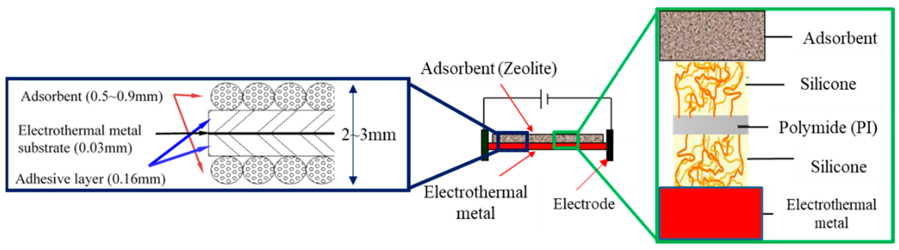
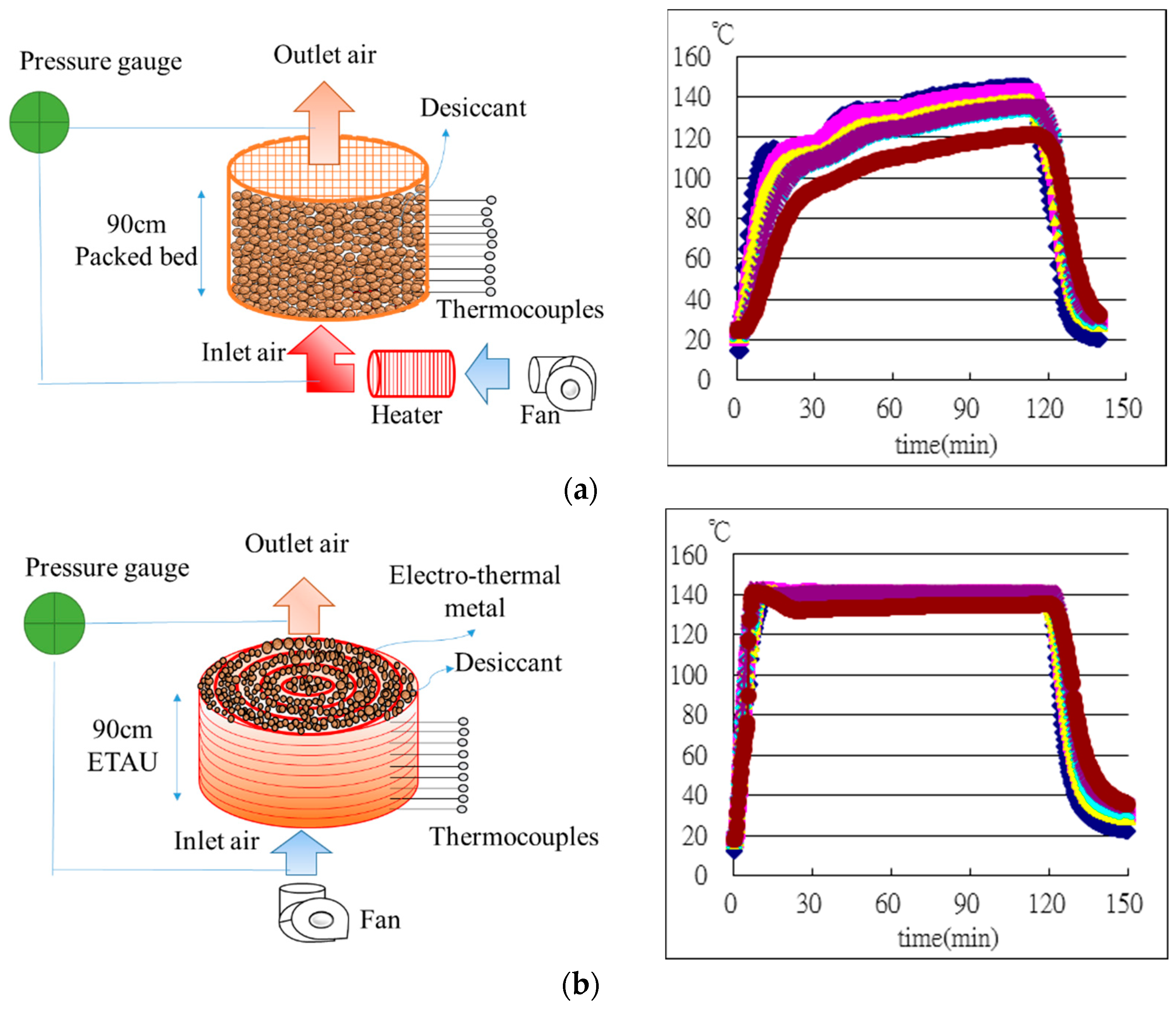
2.1. Electrothermal Adsorbent Unit (ETAU) Regeneration Method

Figure 5 presents a comparison of indirect and direct heating systems. In the indirect heating method (Figure 5a), air flows over an electrically heated plate maintained at a constant temperature (Tm). First, the air is heated to a temperature (Tair), following which it flows over a layer of adsorbent granules, whose temperature is denoted as Tad. In the direct heating method (Figure 5b), a layer of adsorbent granules is attached to the plate using an adhesive. Electrical heat is transferred from the plate to the adsorbent through conduction. As indicated by the thermal resistance diagrams, in the indirect heating method, the transfer path of electrical heat toward the adsorbent comprises two forced convective resistances, one between the plate and air, (1/(hconv Asurface)), and another between air and the adsorbent, (1/(hconv Agrain)). hconv is a heat transfer coefficient of the airflow at Tair, whereas Asurface and Agrain are the areas of the plate and adsorbent granules in contact with air, respectively. By contrast, in the direct heating method, the only impedance is the conductive resistance between the plate and the adsorbent (d/(kad Acontact)). d, kad, and Acon are the granule diameter, the thermal conductivity of the adsorbent, and total contact area of the adsorbent between the plate and adhesive, respectively. To compare the performance of the two methods, consider an example in which a plate of a known size (5d × d) is used to heat five granules using both methods. The overall resistance in each method is derived based on the following assumptions:
(1)
The adsorbent is zeolite with d = 3 mm and kad = 0.20 W⁄mK.
(2)
In the indirect heating method, the plate heats the air through one of its surfaces (Asurface = 5d2), whereas the adsorbent granules are completely exposed to air (Agrain = 5d2 π). The forced convective coefficient for the low-speed airflow over a solid surface [18] is used: hconv ≅ 10 W⁄(m2 K).
(3)
The thick of the adhesive layer is 0.16~0.2 mm, and the adsorbent’s diameter is 0.5~0.9 mm. Therefore In the direct heating method, the granules are in contact with the plate through the adhesive across 1/10 of the surface area of the adsorbent: Acontact = 1/10 Agrain.
(4)
The desiccant conducts a pressed procession after it adheres to the electrothermal metal, so the thermal resistance between the two is minimal and can be ignored.
In this setup, the overall thermal resistance between the plate and adsorbent is 1061 K/W and 2930 K/W for the direct and indirect methods, respectively. Given the same temperature difference between the plate and the adsorbent, the direct method has 0.36 times lower resistance and, therefore, an approximately three times higher heating rate than the indirect method, meaning that the direct method is more energy efficient.

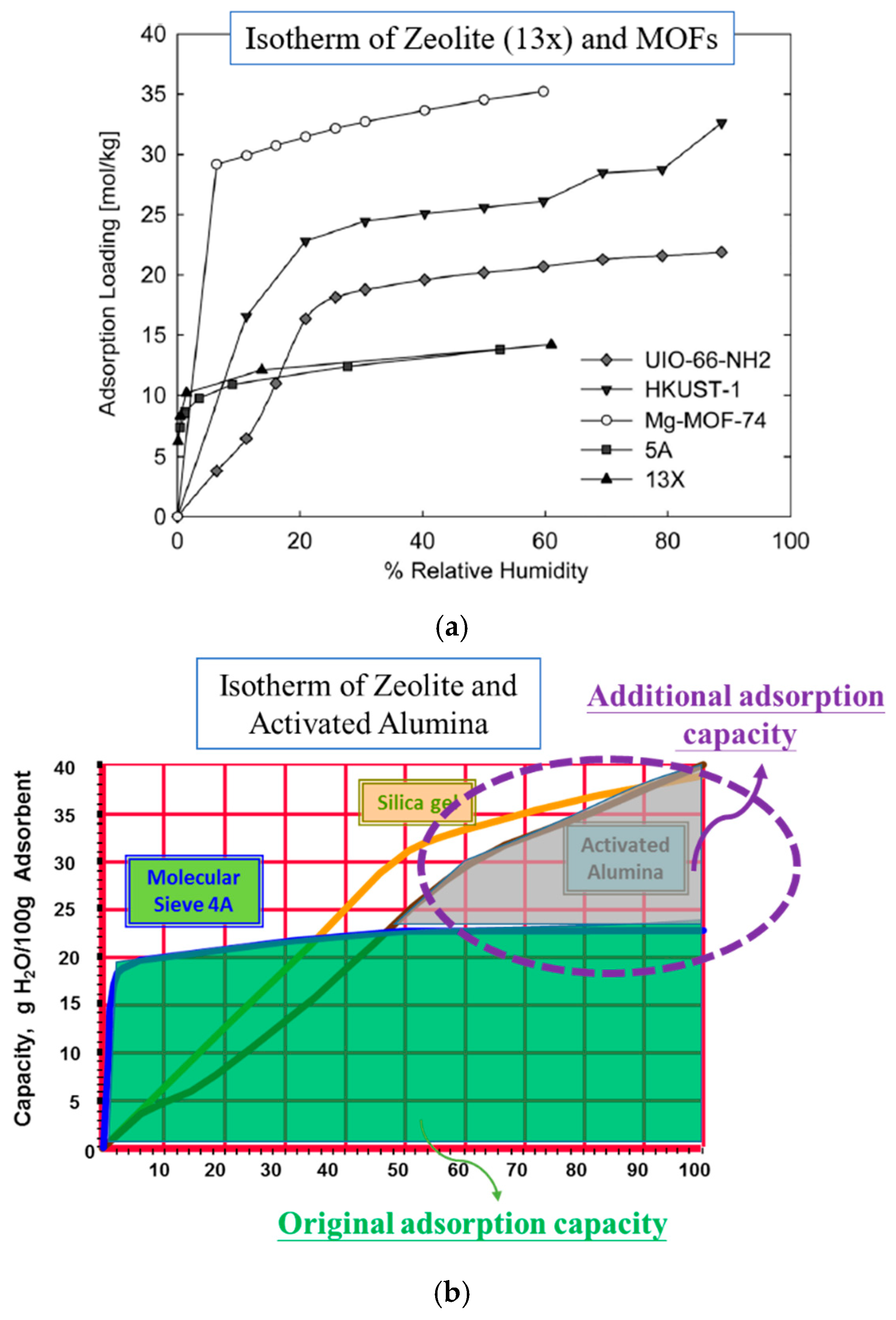
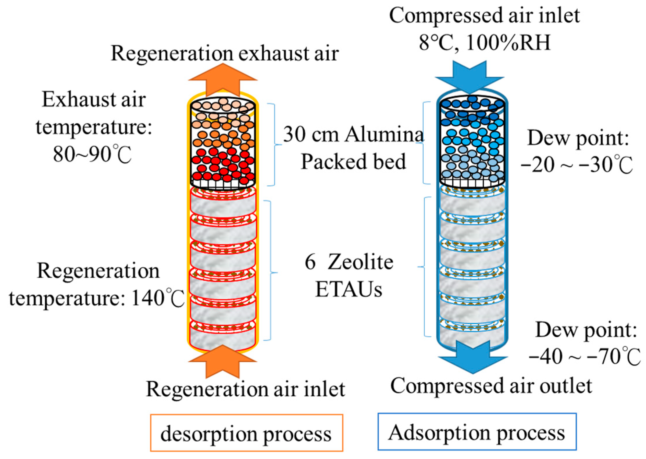
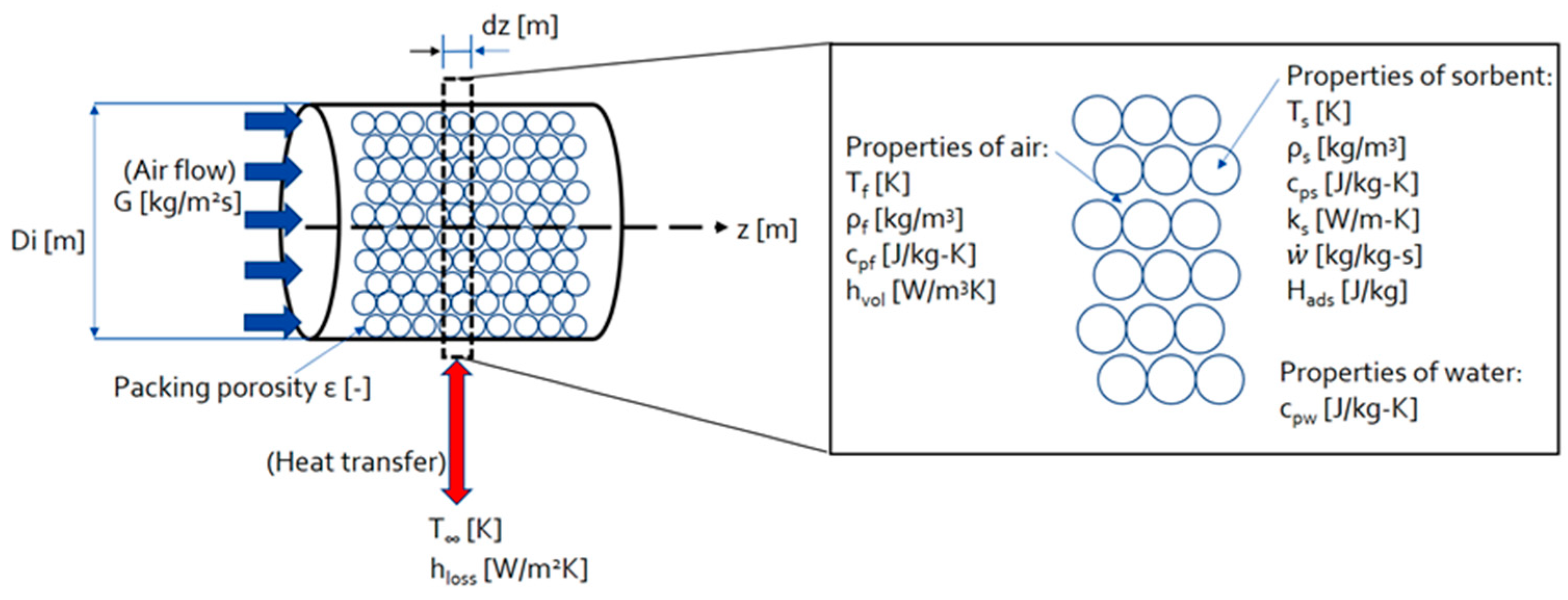
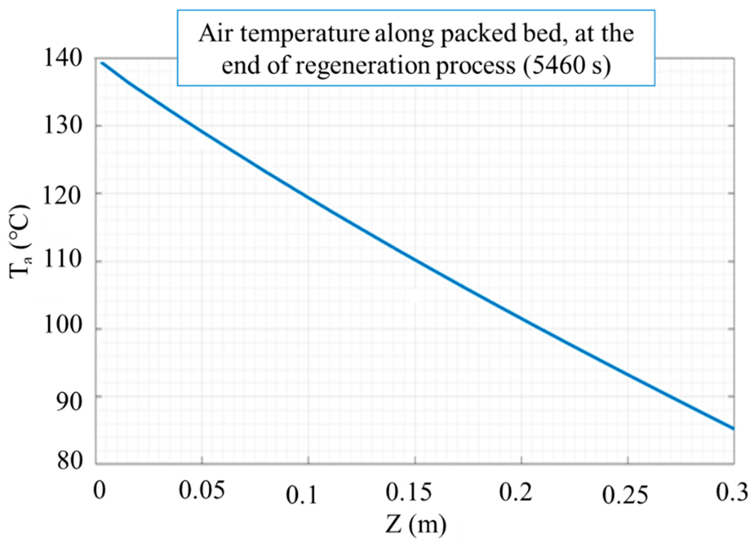
2.2. The Length of the Alumina Packed-Bed in Composite System

Using the exhaust air from ETAUs to regenerate the activated alumina packed-bed, the airflow at the activated alumina packed-bed outlet has a suggested temperature not below 80 °C. Therefore, there is a limit for the length of the packing bed section in the composite setup system. This limit value is desired for the maximum amount of adsorbent in the tank. To estimate it, the authors used a simple thermal analysis, as depicted in Figure 6. It assumes the packing bed as a cylinder of porous medium with known dimensions and physical properties. The bed is subjected to an axial, hot airflow over a period of time, during which the velocity and temperature of the air at the inlet are known. The axial air temperature distribution in the bed at a different time is then be calculated. The packed-bed and airflow parameters used in the analysis are listed in Table 1 and Table 2, respectively, corresponding to our current setup and test measurements. The regenerated temperature of zeolite is 140 °C, and the regeneration flow was controlled at a minimum for saving energy. When the regeneration temperature is reached, the authors keep it for 30 min to ensure that all adsorbents can be completely regenerated. The total regeneration time is about 5460 s.
Furthermore, to calculate the heat transfer rate between air and bed, the heat transfer coefficient should be known. This analysis adopts an empirical correlation for the volumetric heat transfer coefficient hvol (W/m3K) of airflow and a pellet packing bed [19]. The thermal resistance between the desiccant and the electrothermal metal is minimal and can be ignored.
hvol = 700(G/d)0.76
where G is the mass flux of the airflow in kg/m2s, and d is the average diameter of the pellets in m. Other assumptions include that all properties are uniform over the cross-section area of the bed at any axial position. The heat capacity of tank walls and heat transfer between adsorbent pellets are neglected. The authors then calculated the air temperature with the following energy balance equations [4]:
ε ρ f c p f T f t = G c p f T f z h v o l ( T f T s ) + ( 1 ε ) ρ s w ˙ c p w ( T f T s )
( 1 ε ) ρ s c p s T s t = h v o l ( T s T f ) + z ( k s T s z ) + ( 1 ε ) ρ s w ˙ [ H a d s + c p w ( T s T f ) ] 4 h l o s s D i ( T s T )
where T, u, ρ , c, k, and ϵ denote the temperature, velocity, density, specific heat capacity, thermal conductivity, and packing bed porosity, respectively. The symbol z is the distance (m) with a direction that follows the regeneration airflow. Symbol w ˙ (kg/kg s) is the moisture content increase rate of alumina, and H (kJ/kg) is the adsorption heat. Subscripts f and s indicate air and adsorbent. Symbol hloss (kW/m2K) is the heat transfer coefficient of heat loss, Di is the diameter of the packed bed, and T is the temperature of the environment. The results are shown in Figure 7. It can be seen that at the end of the regeneration process, the air temperature drops to 86 °C at a position 30 cm downstream from the bed inlet, which indicates the limit length of the activated alumina packed-bed in our hybrid system.

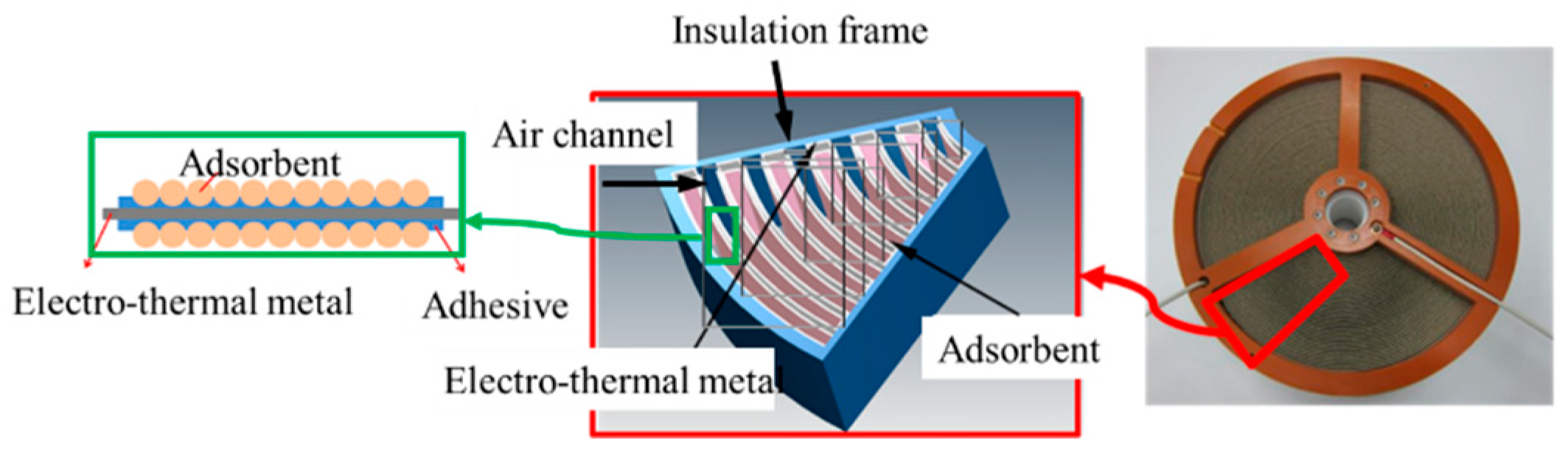
3. Electrothermal Adsorbent Unit (ETAU) Manufacture

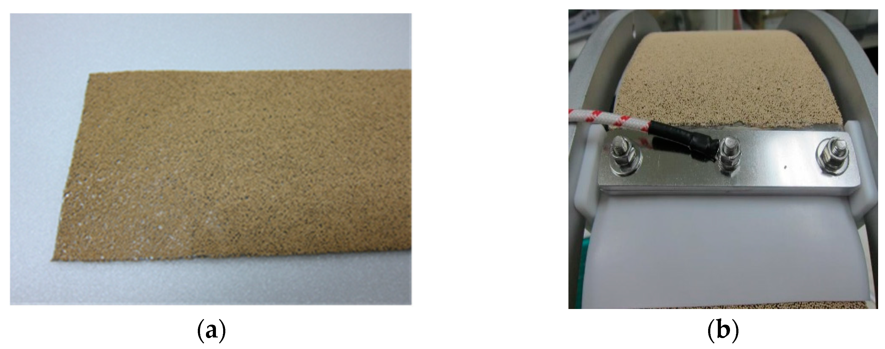
3.1. Desiccant Coating Method
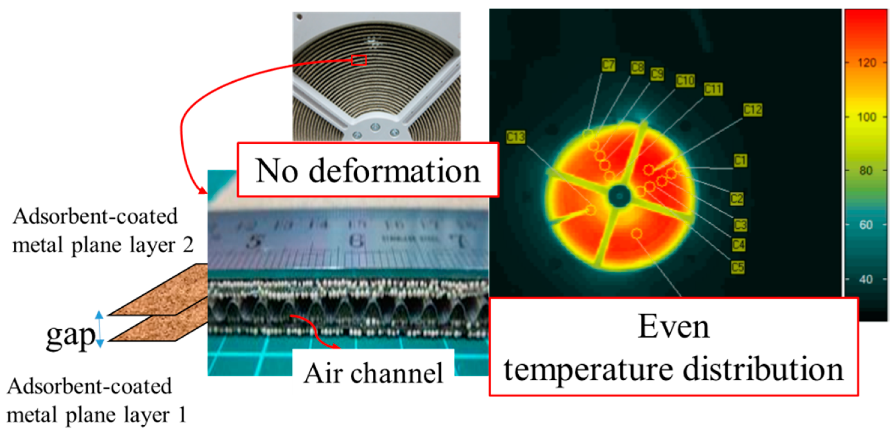
Figure 8 depicts the morphology of ETAU and the structure of the unique adhesive. The electrothermal metal in an ETAU is iron–chrome–aluminum of thickness 0.03 mm, and both sides of the metal are coated with a double-sided adhesive of thickness 0.16 mm. Finally, 4Å zeolite particles with diameters in the 0.5–0.9 mm range are coated on the adhesive to produce the primary sandwich structure of the ETAU. The regeneration temperature of zeolite particles is higher than 140 °C; thus, the adhesive must withstand temperatures exceeding 140 °C. An inorganic double-sided adhesive, silicone, bonds the inorganic adsorbent and the electrothermal metal. The middle layer in the silicone is an organic adhesive, called polyimide, which buffers the upward and downward migration of heat to prevent structural collapse. Figure 9a depicts the adsorbent-coated electrothermal metal sheet. The maximum durability of the unit at temperatures up to 200 °C satisfied the operational requirements. As shown in Figure 9b, the adsorbent remained intact even after the sheet was curled into the wheel. Adsorbent shedding did not occur even after several repeated heating and cooling experiments, proving the unique adhesive worked.

3.2. Air Channel

The final morphology of the proposed ETAU is a wheel; therefore, if the metal sheet is curled without an appropriate gap, the ETAU is distorted by the upward and downward movement of heat (Figure 10). An uneven ETAU shape can disrupt airflow uniformity and decrease the dehumidification performance. A corrugated metal sheet is employed in the proposed technique to form air channels and gaps between the two curled layers in the wheel. When the corrugated metal sheet is placed on the adsorbent-coated electrothermal metal sheet and curled together, air channels and gaps are formed because of the shape of the corrugated sheet. If a wheel has a huge gap, it loses structural support, whereas if a wheel has a minimal gap, it deforms; therefore, a specific sheet with a thickness of 0.05 mm and a width 80 mm was selected for use. After shaping with adsorbent-coated electrothermal metal sheets, the gap (air channel) between two electrothermal metal sheet layers was about 2.5 mm (Figure 11). The distance between the two-channel centers was about 5.0 mm. The measured error and the product tolerance are less than 1%. According to [20,21,22], the Reynolds number (Re) number in the air channel of the ETAU is less than 2300, so the flow is laminar. Therefore, the Nusselt and Sherwood numbers depend on the shape of the air channel, aspect ratio, and thickness ratio in this condition, and their calculated values are 3.34 and 1.46, respectively. Compared with the desiccant packed bed, the parallel channel design in the ETAU reduced the pressure drop and achieved temperature uniformity within the ETAU. Moreover, corrugated metal sheets can withstand the tension strains due to expansion and shrinkage caused by heat and cold shock. According to [23], when the pressure drop in the compressed air system is reduced by 1 kg/cm2, the power consumption of the total system will reduce 4~8%. Thus, ETAU with a low-pressure drop benefits the energy-saving of the entire system.

3.3. Continuous and Rapid Roll-to-Roll Production

An affordable and rapid continuous roll-to-roll procedure was used to produce the ETAU. This procedure, which is conducive to being commercialized, entails the following steps: (a) metal sheet cleaning, (b) adhesive coating, (c) adsorbent coating, and (d) curling with the corrugated metal sheet (Figure 12).
A metal sheet cleaning process was employed to remove the lubricating oil film from the metal sheet in order to ensure adherence of the adhesive. The metal sheet was cleaned, following which both of its sides were coated with double-sided adhesive layers; then, the sheet was subjected to the adsorbent coating process. Finally, the adsorbent-coated structure was curled to form a wheel. The upper and lower parts of the frame, which supports the ETAU, were fabricated from nonconductive Teflon. After electrode assembly, the side of the ETAU was filled with cotton insulation and covered with iron support frames. The ETAU was subjected to a voltage resistance test of 2.5 kV/60 s to ensure its stability. The diameter of ETAU is designed to be 385 mm to match the size of pressure buckets presently used in compressed dry air systems, and the height of the proposed ETAU product is 113 mm. Figure 13 illustrates a structural schematic of the ETAU. The desiccant weight in an ETAU is about 3.8 kg. No problems were noted while the ETAU was operated for over 2000 h.

4. Performance Test Result and Discussion

Table 3 characterizes the measurement devices used in the experiment. ETAUs were installed in pressure buckets, and the temperature was measured at numerous points by using K-type thermocouples. After adjustment, the measurement accuracy was ±0.5 °C. Mirror dew point meters with an accuracy of ±0.2 °C were utilized at the inlets and outlets of the compressed air dryers. The flowmeter measurement ranged from 8 to 80 m/s, with an accuracy of ±1%. The pressure gauge measurement range was −101 to 2944 kPa, with an accuracy of ±2 kPa. The accuracy of the electricity meter measurements was ±0.1%. In this study, the experimental error was identical to the instrumental error. The energy efficiency index is defined as follows:
E n e r g y   e f f i c i e n c y   i n d e x   = E n e r g y   c o n s u m p t i o n   ( k W ) S u p p l y   c o m p r e s s e d   a i r   ( C M M ) .
The temperature measuring point tightly adheres to the adsorbent, and the position is in the middle of the radius of each ETAU. The height of the temperature sensor is in the middle of the thickness in each ETAU. This temperature measurement point represents the entire ETAU’s temperature. The pressure gauges are installed at the inlet and outlet of the test systems.

4.1. ETAU Basic Test

The horizontal temperature distribution of the ETAU was obtained through infrared temperature measurement tests (Figure 11). Unlike a conventional packed-bed system, the proposed ETAU has air channels and uses a unique heating method—direct conductive heat transfer—which guarantees uniform horizontal temperature distribution. Regarding vertical temperature distribution, the compared test result with a 90 cm tall system was shown in Figure 14. The diameter of them is 385 mm. The nine colored curves in the two diagrams indicate the temperature at each 10 cm height in the system. A conventional heated-air-flow system must exhibit a temperature gradient in the vertical direction, as shown in Figure 14a. Even after 140 min of heating, the last three layers of the conventional system did not achieve the setup temperature of 140 °C, and 70 min were required to increase the temperature of the first layer to 140°C. By contrast, the ETAU system (Figure 14b) only needed 15 min to reach the setup temperature; moreover, the power supply to each ETAU could be controlled individually, meaning that a uniform vertical temperature distribution could be achieved easily. Consequently, the required regeneration time of the ETAU system was reduced, and the uniformity was increased by approximately 78% and 42%, respectively. The packed bed’s pressure drop and the ETAU are 678 Pa and 208 Pa, respectively, when the airflow is 1 m3/min. (CMM) at atmospheric pressure.

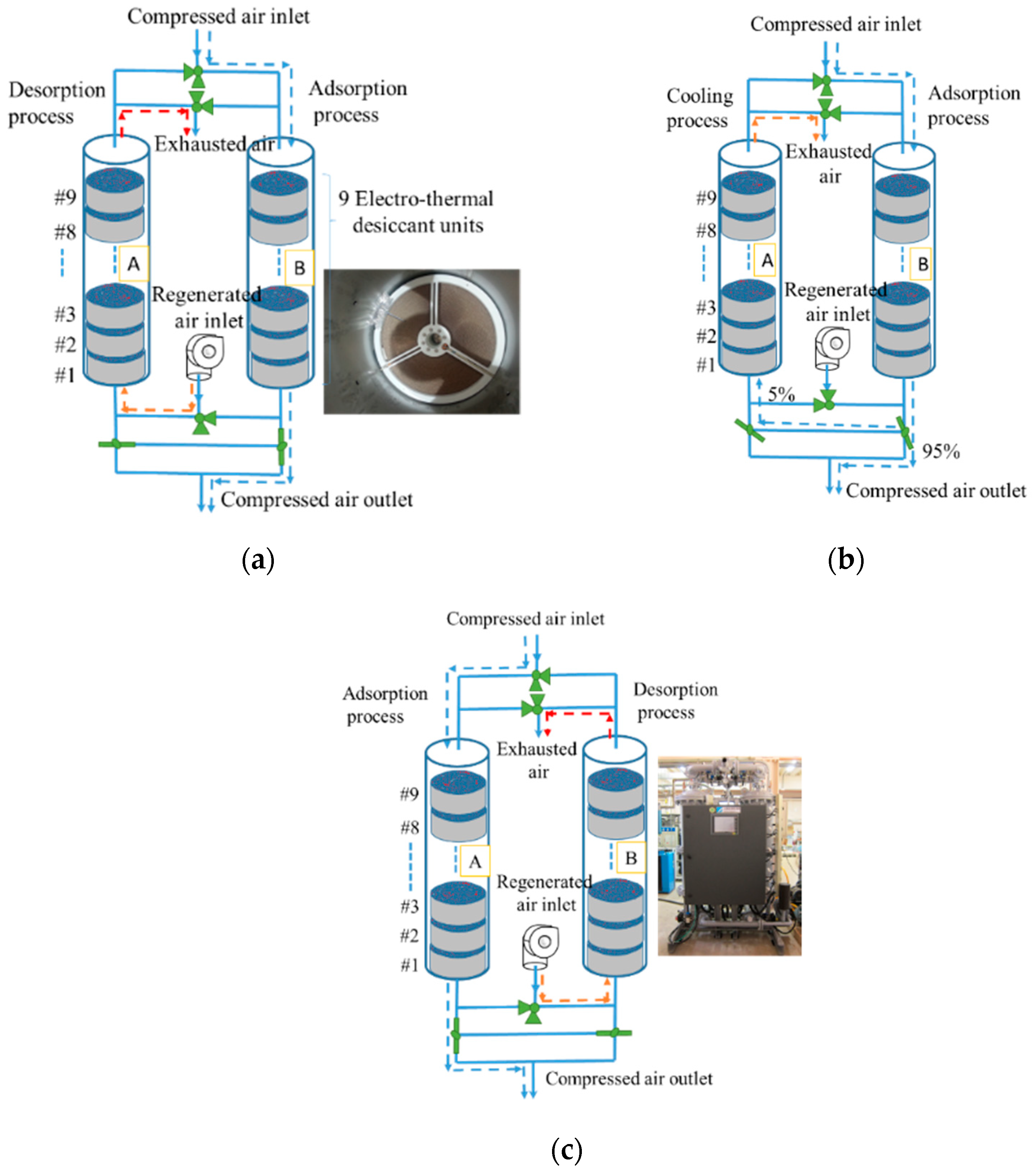
4.2. ETAUs Compressed Air Dryer

Table 4 lists the pressure, temperature, relative humidity, and dew point measurements for the procedure of the compressed air drying system. Air was compressed using a compressor; consequently, considerable heat was released, which increased the air temperature to 43 °C. Moreover, the water content in the air decreased because of the compression. After the compressed air was dehumidified through a refrigeration chiller, the compressed air temperature was reduced to approximately 8 °C, and the dew point of it drops to about −18 °C. This low temperature and high relative humidity condition are beneficial for adsorption drying, so the dew point of compressed air was reduced to less than −40 °C after through the adsorption dryer.
The refrigeration chiller can reduce a lot of dehumidification load of adsorption dryers. However, if the compressed air goes directly through the adsorption without refrigeration dryers, the adsorption time must decrease when the regeneration condition is the same.
Figure 15 illustrates the configuration of the 3-CMM ETAU compressed air dryer that features a twin-tower structure. This commercial system uses a timer to switch between adsorption and desorption modes. Nine 10 cm thick of ETAUs were used in each tower to ensure adequate system performance. Figure 15a depicts the regeneration step for tower A, in which the ETAU is powered and is heated. Simultaneously, in tower B, the adsorption step sets the dew point of the compressed air of the outlet lower than −40 °C. After completing the regeneration step in tower A, the valve is switched, and the cooling step is executed. Figure 15b indicates that 5~10% of the dry compressed air from the tower B outlet is diverted back to tower A for cooling the adsorbent. The temperature of zeolite must be lower than 80 °C so that the proper adsorption performance can be shown. The humidity of the atmosphere air is too high. Therefore, if the atmosphere air is used to cool the zeolite, the dehumidification process will happen in the cooling step. The situation is not expected, so the dry air from the high-pressure air outlet must be used for cooling. After the adsorbent is cooled, the outlet of tower A is closed, and pressure is generated in tower A and maintained constant. When the dew point of tower B outlet increases to more than −40 °C, the system undergoes a short period of parallel adsorption, during which adsorption occurs in both towers A and B. Finally, the valve is switched to start the regeneration step in tower B and adsorption in tower A (Figure 15c). Repeated cycles enable the ETAU double-tower system to continually produce dry compressed air at a dew point of −40 °C.
In contrast to conventional heating practices, the ETAU directly heats the adsorbent by using an electrothermal metal; therefore, if the system uses copious regeneration flow, the adsorbent is cooled. However, desorption vapors from the adsorbent cannot move out without regeneration flow, so the regeneration flow was controlled at a minimum for saving energy. The airflow used was listed in Table 2. The first ETAU is marked #1 (regeneration inlet), the second #2, and so on (Figure 15). Though on-off controller, the regeneration temperature of all ETAUs reached 140 °C in 30 min., as shown in Figure 16. Because the exhausted air from #1 must be preheated the #2, the on-off control frequency at #2 must lower than #1. The first ETAU had the largest temperature-increasing load, so the temperature setting goal of #1 was slower and step by step. The total regeneration time was 1.5 h to make sure all desiccants can total regenerated. After transfer to the cooling step, the cooling rate of the ETAUs were also faster due to the air channels. The temperature of all ETAUs can lower than 60 °C in 1 h when the cooling flow is about 0.21 m3/min. (CMM), which is 7.3% of the supply of dry compressed air. Both the regeneration and cooling flows used in the ETAU system were less than traditional heat-air-flow compressed air dryers benefiting the energy-saving of the total system. The adsorption period ended when the dew point of outlet compressed air was higher than −40 °C, and the authors defined this as the adsorption time. The parameters of the system can be varied according to the operating environmental conditions and the requirements of the application. Table 5 compiles the test results of the ETAU compressed air dryer in different test conditions. The dehumidification load decreased when the compressed air flow or dew point of inlet compressed air is reduced, so the adsorption time of ETAU compressed air dryer can increase. Moreover, the dew point of outlet compressed air was lower when the air volume or dew point of inlet air was drop off, which means the moisture retention time subtle increased. However, the adsorption time was not in a proportional increase relationship with this alteration, as shown in Table 5.

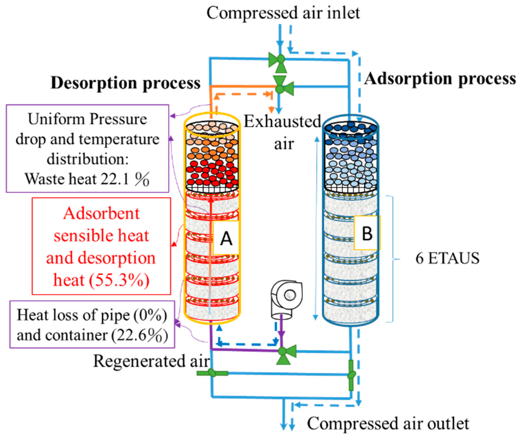
4.3. Composite ETAUs Compressed Air Dryer

Another disadvantage of the traditional compressed air dryer is the high temperature of the exhaust air. The authors used a 30 cm thick alumina packed-bed to replace the top three ETAUs in the nine ETAUs compressed air dryer, and the exhaust air from the ETAUs can be used for the regeneration process of the activated alumina, which regeneration temperature is 80 °C. As shown in Figure 17, the final exhaust air temperature is only about 80 °C. The result is a little different from our prediction because the thermal capacity of the tank wall was ignored in our prediction. The heat source comes from the ETAUs, so the heat loss of the container is less compared with traditional heated-air regeneration systems. However, the activated alumina regeneration process just like a conventional method of heating by exhaust air, so the last 10 cm alumina packed-bed, marked #3, only had the highest temperature, 80 °C. Alumina #1 had a temperature of 130 °C, and Alumina #2 reached 100 °C. The lower regeneration temperature makes activated alumina have a mediate dehumidification performance, but the zeolite loses its dehumidification performance if the regeneration temperature is as low as 80~100 °C. The 30 cm activated alumina packed-bed makes the dew point of compressed air reduce to −20~−30 °C. It means the dehumidification load of zeolite in the ETAU is diminished. The dew point of compressed air is finally under -40 °C due to the zeolite, which is wholly regenerated at 140 °C in the ETAUs. During the cooling stage of the composite ETAUs system, the activated alumina above will continue to be heated because the hot air blowing upwards from below. Therefore, after the final cooling stage is completed, the temperature of the last layer of activated alumina will be about 80 °C, which can ensure that all activated alumina is completely regenerated. The experimental results are shown in Figure 18. At the same inlet dew point of −8~−10 °C and the outlet dew point of −40 °C, the composite system has a longer adsorption time. The regeneration time is 90 min, and the cooling time is 60 min in both systems. The composite system has higher dehumidification performance due to the presence of the activated alumina. The adsorption capacity of activated alumina is higher than that of zeolite, so a load of zeolite is significantly reduced. The adsorption time can be extended by 1 h compared with the nine ETAUs system. The regeneration energy consumption is also reduced due to only 6 ETAUs in the composite ETAUs system, so the energy consumption index reduces about 10%, down to 0.86 kW/CMMcompressed air.
Table 6 compares the performance of commercial adsorption dryers and the proposed ETAU prototype systems. The heatless adsorption system exhibited an energy efficiency index of approximately 2.31 kW/CMMcompressed air. Moreover, the compressed air consumption ratio in the cooling (regeneration) step was approximately 30.1%. The heated-air-flow adsorption system exhibited an energy efficiency index of roughly 1.19 kW/CMMcompressed air. The compressed air consumption ratio in the cooling step is one of the critical factors affecting the energy consumption in the adsorption dryer. Efficient regeneration and cooling methods can considerably reduce the energy use of compressed air. The ETAU system exhibited the best performance because of the direct heating adsorbent. Furthermore, the uniform air channels made the compressed air consumption ratio of the ETAU only 7.3% in the cooling step. The compressor used 7.7 kW to produce one compressed air unit (m3/min., CMM), yielding an air consumption energy index in the cooling step of 0.56 kW/CMMcompressed air in all the ETAU systems. The regeneration energy and total energy efficiency indices of the ETAU system were 0.41 kW/CMMcompressed air and 0.91 kW/CMMcompressed air, respectively. In terms of the composite ETAU system, the regeneration energy and total energy efficiency indices were 0.32 and 0.86 kW/CMMcompressed air.

5. Conclusions

Figure 19 presents the energy analysis of the proposed composite ETAU system. Because there is insulating cotton around each ETAU, and no heating on the pipe, the heat losses of pipes and the container were 0% and 22.6%, respectively. Moreover, the uniform pressure drop and temperature distributions of the ETAU system are achieved without any overheating. The exhaust heat waste in the composite ETAU system was as low as 22.1%. The adsorbent regeneration process used 55.3% of the total energy, indicating that the ETAU system is relatively more efficient. Compared with commercially available heated-air adsorption dryers, the composite ETAU system saves energy consumption by 27% through electrothermal regeneration technic and composite system configuration.
In the proposed and successfully developed ETAU, the proposed adsorbent (zeolite) was attached to the electrothermal metal by using a heat-resistant adhesive. Wheel-shaped units were manufactured through a high-efficiency, low-cost, roll-to-roll process. The manufactured ETAUs exhibited low-pressure drop and uniform temperature distribution because the ETAU design had air channels. Experimental results revealed that the temperature uniformity and regeneration time of the ETAU dryers were twice and one-third that of the heated-air-flow dryers, respectively. The energy consumption index of the ETAU compressed air dryer prototype was 0.97 kW/CMMcompressed air, and the composite ETAU one was 0.86 kW/CMMcompressed air, indicating energy savings of more than 25% compared with conventional adsorption dryers. This innovative adsorbent regeneration method for compressed air dryers yielded remarkable results and is suitable for other adsorbent applications.

Author Contributions

Conceptualization, Y.-H.K. and C.-H.C.; methodology, Y.-H.K.; software, J.-H.L.; validation, J.-C.P., C.-H.C. and Y.-H.K.; formal analysis, J.-H.L.; investigation, C.-H.C.; resources, M.-L.H.; data curation, J.-C.P.; writing—original draft preparation, C.-H.C.; writing—review and editing, C.-H.C.; visualization, M.-L.H.; supervision, J.-J.C.; project administration, Y.-H.K. All authors have read and agreed to the published version of the manuscript.

Funding

This research received no external funding.

Data Availability Statement

Restrictions apply to the availability of these data. Data was obtained from Ministry of Economics Affairs, Taiwan and are available from the authors with the permission of Ministry of Economics Affairs, Taiwan. (https://www.moeaboe.gov.tw/ECW/populace/home/Home.aspx, accessed on 21 June 2021).

Acknowledgments

The authors would like to acknowledge the support from the Energy Fund of Ministry of Economics Affairs, Taiwan. Moreover, we extend our appreciation to Chang-Yi Shen for generating the figures. This manuscript was edited by Wallace Academic Editing.

Conflicts of Interest

The authors declare no conflict of interest.

References

  1. Nehler, T. Linking energy efficiency measures in industrial compressed air systems with non-energy benefits—A review. Renew. Sustain. Energy Rev. 2018, 89, 72–87. [Google Scholar] [CrossRef]
  2. Zhan, C.; Yin, Y.; Guo, X.; Jin, X.; Zhang, X. Investigation on drying performance and alternative analysis of different liquid desiccants in compressed air drying system. Energy 2018, 165, 1–9. [Google Scholar] [CrossRef]
  3. Sun, H.; Luo, X.; Wang, J. Feasibility study of a hybrid wind turbine system—Integration with compressed air energy storage. Appl. Energy 2015, 137, 617–628. [Google Scholar] [CrossRef] [Green Version]
  4. Barbour, E.; Mignard, D.; Ding, Y.; Li, Y. Adiabatic Compressed Air Energy Storage with packed bed thermal energy storage. Appl. Energy 2015, 155, 804–815. [Google Scholar] [CrossRef] [Green Version]
  5. Yin, Y.; Zheng, B.; Yang, C.; Zhang, X. A proposed compressed air drying method using pressurized liquid desiccant and experimental verification. Appl. Energy 2015, 141, 80–89. [Google Scholar] [CrossRef]
  6. Senanayake, N.S.; Dissanayake, D. Activated carbon for drying compressed air for low pressure applications. Int. Rev. Mech. Eng. 2011, 5, 818–821. [Google Scholar]
  7. Guo, P.; Wong-Foy, A.G.; Matzger, A.J. Microporous Coordination Polymers as Efficient Sorbents for Air Dehumidification. Langmuir 2014, 30, 1921–1925. [Google Scholar] [CrossRef] [PubMed]
  8. Chen, C.-H.; Huang, P.-C.; Yang, T.-H.; Chiang, Y.-C.; Chen, S.-L. Polymer/alumina composite desic-cant combined with periodic total heat exchangers for air-conditioning systems. Int. J. Refrig. 2016, 67, 10–21. [Google Scholar] [CrossRef]
  9. Fu, H.-X.; Zhang, L.-Z.; Xu, J.-C.; Cai, R.-R. A dual-scale analysis of a desiccant wheel with a novel organic–inorganic hybrid adsorbent for energy recovery. Appl. Energy 2016, 163, 167–179. [Google Scholar] [CrossRef]
  10. Chua, K.J.; Chou, S.; Yang, W.; Yan, J. Achieving better energy-efficient air conditioning—A review of technologies and strategies. Appl. Energy 2013, 104, 87–104. [Google Scholar] [CrossRef]
  11. Angrisani, G.; Roselli, C.; Sasso, M. Effect of rotational speed on the performances of a desiccant wheel. Appl. Energy 2013, 104, 268–275. [Google Scholar] [CrossRef]
  12. Chen, C.-H.; Ma, S.-S.; Wu, P.-H.; Chiang, Y.-C.; Chen, S.-L. Adsorption and desorption of silica gel circulating fluidized beds for air conditioning systems. Appl. Energy 2015, 155, 708–718. [Google Scholar] [CrossRef]
  13. Enteria, N.; Yoshino, H.; Satake, A.; Mochida, A.; Takaki, R.; Yoshie, R.; Baba, S. Development and construction of the novel solar thermal desiccant cooling system incorporating hot water production. Appl. Energy 2010, 87, 478–486. [Google Scholar] [CrossRef]
  14. Eicker, U.; Schneider, D.; Schumacher, J.; Ge, T.; Dai, Y. Operational experiences with solar air collector driven desiccant cooling systems. Appl. Energy 2010, 87, 3735–3747. [Google Scholar] [CrossRef]
  15. Chen, C.-H.; Hsu, C.-Y.; Chiang, Y.-C.; Chen, S.-L. Silica gel/polymer composite desiccant wheel combined with heat pump for air-conditioning systems. Energy 2016, 94, 87–99. [Google Scholar] [CrossRef]
  16. Hao, W.; Björkman, E.; Lilliestråle, M.; Hedin, N. Activated carbons prepared from hydrothermally car-bonized waste biomass used as adsorbents for CO2. Appl. Energy 2013, 112, 526–532. [Google Scholar] [CrossRef]
  17. Karmakar, A.; Prabakaran, V.; Zhao, D.; Chua, K.J. A review of metal-organic frameworks (MOFs) as energy-efficient desiccants for adsorption driven heat-transformation applications. Appl. Energy 2020, 269, 115070. [Google Scholar] [CrossRef]
  18. Whitelaw, J.H. Convective Heat Transfer. 2011. Available online: http://dx.doi.org/10.1615/AtoZ.c.convective_heat_transfer (accessed on 14 January 2017).
  19. Coutier, J.; Farber, E. Two applications of a numerical approach of heat transfer process within rock beds. Sol. Energy 1982, 29, 451–462. [Google Scholar] [CrossRef]
  20. Niu, J.; Zhang, L. Heat transfer and friction coefficients in corrugated ducts confined by sinusoidal and arc curves. Int. J. Heat Mass Transf. 2002, 45, 571–578. [Google Scholar] [CrossRef]
  21. Zhang, L.Z.; Niu, J.L. A Numerical Study of Laminar Forced Convection in Sinusoidal Ducts with Arc Lower Boundaries under Uniform Wall Temperature. Numer. Heat Transf. Part A Appl. 2001, 40, 55–72. [Google Scholar] [CrossRef]
  22. Zhang, L.Z. Conjugate Heat and Mass Transfer in Heat Mass Exchanger Ducts; Academic Press: Cambridge, MA, USA, 2014; pp. 21–74. [Google Scholar]
  23. Edwin, M. Talbott, Compressed Air Systems: A Guidebook on Energy and Cost Savings, 2nd ed.; The Fairmont Press: Lilburn, GA, USA, 1993. [Google Scholar]
Figure 1. Energy analysis of heated-air-flow compressed air dryer.
Processes 09 01082 g001
Figure 2. Structure of the main components in the proposed direct electrothermal regeneration technique.
Processes 09 01082 g002
Figure 3. (a) Isotherm adsorption curve of different desiccants, and (b) Adsorption capacity of the composite desiccant construction system.
Processes 09 01082 g003
Figure 4. Operation principle of the composite system.
Processes 09 01082 g004
Figure 5. Comparison of (a) indirect and (b) direct heating systems.
Processes 09 01082 g005
Figure 6. Depiction of the adsorbent packing bed section subjected to airflow.
Processes 09 01082 g006
Figure 7. Air temperature distribution in the adsorbent packing bed at the end of the regeneration process.
Processes 09 01082 g007
Figure 8. Special adhesive in an ETAU.
Processes 09 01082 g008
Figure 9. Adsorbent-coated electrothermal metal sheet (a) before and (b) after curling.
Processes 09 01082 g009
Figure 10. ETAU without air channel and gaps.
Processes 09 01082 g010
Figure 11. ETAU with parallel channel design.
Processes 09 01082 g011
Figure 12. Continuous roll-to-roll ETAU manufacturing procedure.
Processes 09 01082 g012
Figure 13. Structural schematic of the proposed ETAU.
Processes 09 01082 g013
Figure 14. Temperatures at different heights in (a) a conventional heated-air-flow system and (b) the proposed ETAU system.
Processes 09 01082 g014
Figure 15. System configuration of an ETAU compressed air dryer: (a) regeneration, (b) cooling, (c) and adsorption steps in tower A.
Processes 09 01082 g015
Figure 16. Temperature curves of the ETAU system.
Processes 09 01082 g016
Figure 17. Temperature curves of the composite ETAU system.
Processes 09 01082 g017
Figure 18. Schematic diagram of (a) ETAU system and (b) composite ETAU system.
Processes 09 01082 g018
Figure 19. Energy analysis of the composite ETAU system.
Processes 09 01082 g019
Table 1. Design parameters of material used for the packed-bed section.
Packing Bed
Diameter (mm)610
Length (mm)300
Packing porosity0.27
Initial temperature (°C)40
Activated alumina adsorbent
Particle diameter (mm)4
Density (kg/m3)1053
Specific heat capacity (J/kgK)880
Table 2. Design parameters of regeneration airflow.
Step12345
Duration (s)0–6060–160160–41604160–42604260–5460
Inlet temperature (°C)140
Velocity (10−3 m/s)39.634.278.422.934.2
Table 3. Measurement devices used in the experiment.
EquipmentRangeError
K-type thermocouples0~260 °C±0.5 °C
Inlet mirror dew point meters−35 to −10 °C±0.2 °C
Outlet mirror dew point meters−65 to −25 °C±0.2 °C
Vortex Flowmeter8 to 80 m/s±1%
Pressure gauge−101 to 2944 kPa±2 kPa
Electricity meterMaximum current 80 A±0.1%
Table 4. The procedure of the compressed air drying system.
AtmosphereAfter CompressedAir Storage BarrelRefrigeration DryerAdsorption Dryer
Pressure (kPa) 101885876865836
Temperature (°C)304325825
Relative humidity (%RH)
(High pressure)
-100%100%100%2.6%
Relative humidity (%RH)
(Atmosphere)
80%12%11.5%11.3%0.3%
Pressure dew point (°C)-43258−22.2
Dew point (°C)26.17.5−6.1−18.3−42
Table 5. ETAU compressed air dryer test results.
Supply Air
(m3/min., CMM)
The Adsorption Time
(Before the Dew Point of Outlet Air Was Higher Than −40 °C)
The Dew Point of Inlet Compressed Air: −8~−10 °CThe Dew Point of Inlet Compressed Air: −18~−20 °C
33 hours4 hours
1.83.5 hours5 hours
Table 6. Performance of a commercial adsorption dryer and the proposed ETAU system.
Adsorption Dryer TypeHeatlessHeat-Air-FlowETAUComposite ETAU
Outlet dew point (°C)−40−40−40−40
Inlet air flow (m3/min.,CMM)3.112.863.013.00
Outlet air flow (m3/min., CMM)2.172.622.792.78
Compressed air consumption ratio in cooling step (%)30.18.17.37.3
Compressed air consumption energy index (kW/CMMcompressed air)2.310.620.560.56
Regeneration energy index (kW/CMMcompressed air)---0.570.410.32
Total energy efficiency index (kW/CMMcompressed air)2.311.190.970.86
Publisher’s Note: MDPI stays neutral with regard to jurisdictional claims in published maps and institutional affiliations.

