Analysis of Turn-to-Turn Fault on Split-Winding Transformer Using Coupled Field-Circuit Approach
Abstract
:1. Introduction
2. Analysis Method and Validation
- The conductivity of the material is constant and the influence of temperature change on the conductivity is ignored.
- The skin effect and proximity effect of windings are neglected.
Solution Method
3. Results and Discussion
3.1. Magnetic Field Analysis
3.2. Current Analysis
3.3. Force Analysis
4. Conclusions
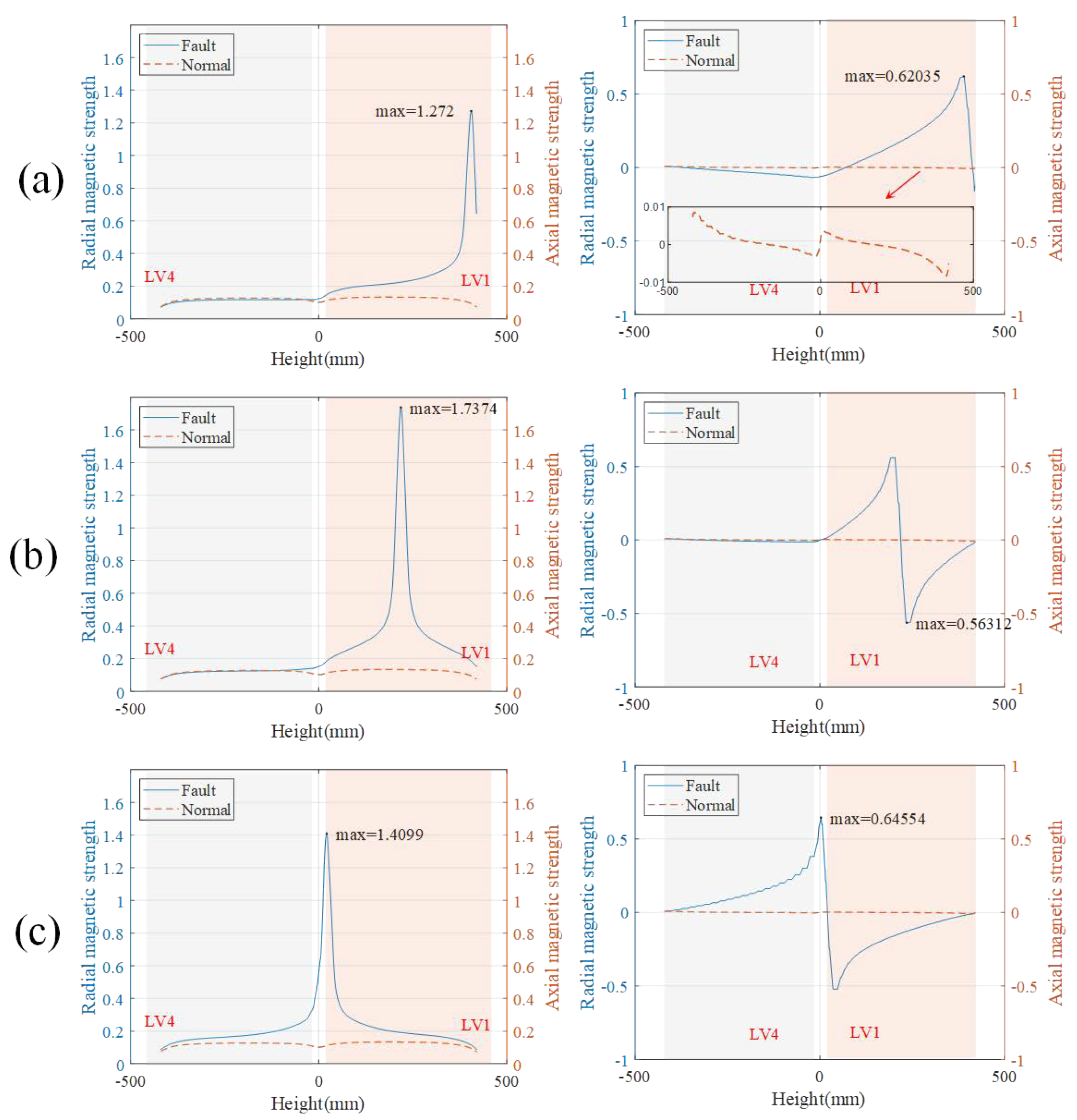
- The results show that the magnetic leakage field is distorted after short circuit, and the magnetic leakage field produced by the TTFs at different positions is different. The maximum axial magnetic flux leakage caused by the middle TTF is 1.74 T, and the maximum radial magnetic flux leakage caused by bottom short circuit is 0.56 T. The distribution of magnetic field in the core is analyzed. When the TTF occurs, the local magnetic saturation of the core is serious, which can result in more severe vibration and noise of the core.
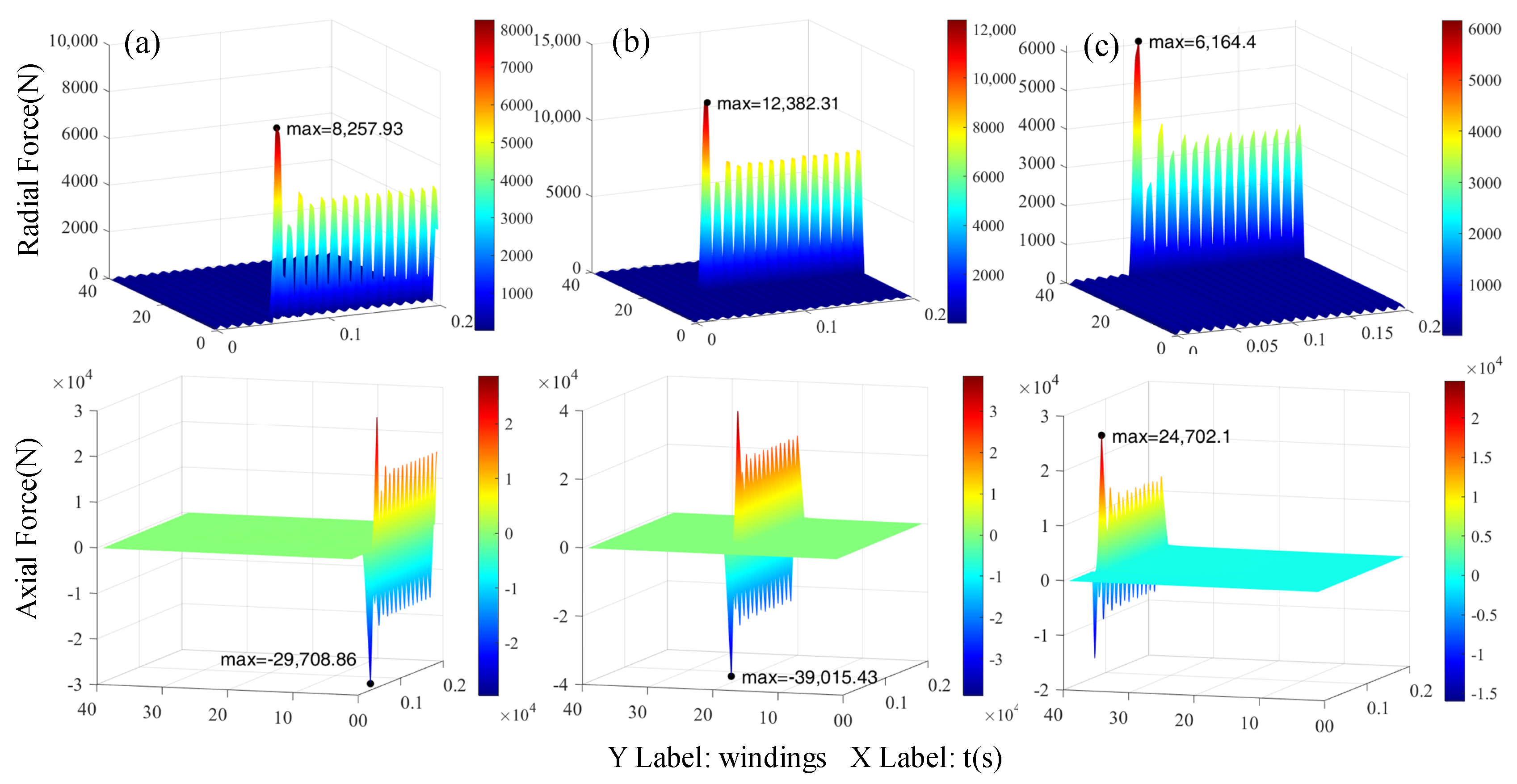
- Based on the analysis of the per-turn force and resultant force of the short-circuit winding, the radial and axial electromagnetic force of the winding under normal operation and TTFs is basically consistent with the distribution law of the axial and radial leakage magnetic field of the winding in the above conclusion. The axial resultant force is increased by 14 times under the top and the bottom TTFs, and the radial resultant force is increased by 3.2 times under the middle TTF. It should be noted that when the middle part of the winding is short circuited, the axial force on both sides of the winding is opposite, resulting in a small axial force of the short-circuit winding, which is only increased by 1.3 times.
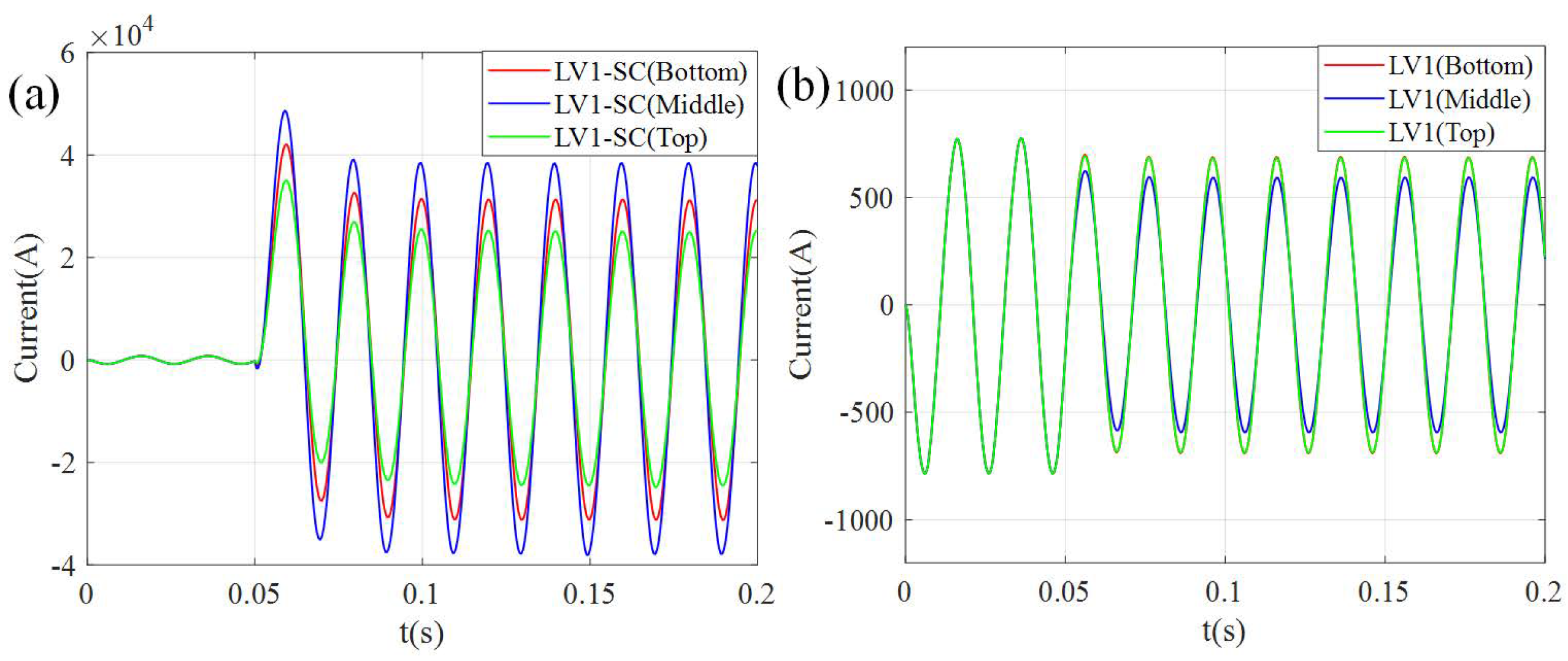
- The influence of TTFs at different positions on the current relationship of other windings is studied. The coupling of windings on the same core column is strong, and the coupling between windings on different cores is weak. When the middle TTF occurs, it has the least influence on the current of other windings. In addition, it is worth noting that when the location of TTF is adjacent to the same core winding, the short circuit fault will have a greater impact on current of the adjacent winding. When the bottom is short circuited, the steady-state current of the high-voltage winding axially adjacent to the short-circuit winding increases by 8%, and the steady-state current of the low-voltage winding axially adjacent to the short-circuit winding decreases by 7%, respectively.
- The influence of TTFs at different positions on the force of other windings is studied. The results show that the axial force of the branch winding on the two cores is greatly affected by the TTFs, while the radial force of other windings on the same mandrel has a greater influence, and the change of radial force on the other core column can be ignored.
Author Contributions
Funding
Data Availability Statement
Acknowledgments
Conflicts of Interest
References
- Amoiralis, E.I.; Tsili, M.A.; Kladas, A.G. Transformer Design and Optimization: A Literature Survey. IEEE Trans. Power Deliv. 2009, 24, 1999–2024. [Google Scholar] [CrossRef]
- Chase, D.D.; Garin, A.N. Split Winding Transformers. Trans. Am. Inst. Electr. Eng. 1934, 53, 914–922. [Google Scholar] [CrossRef]
- Kladas, A.G.; Papadopoulos, M.P.; Tegopoulos, J.A. Leakage Flux and Force Calculation on Power Transformer Windings under Short-Circuit: 2D and 3D Models Based on the Theory of Images and the Finite Element Method Compared to Measurements. IEEE Trans. Magn. 1994, 30, 3487–3490. [Google Scholar] [CrossRef]
- Gholami, M.; Hajipour, E.; Vakilian, M. A Single Phase Transformer Equivalent Circuit for Accurate Turn to Turn Fault Modeling. In Proceedings of the 2016 24th Iranian Conference on Electrical Engineering (ICEE), Shiraz, Iran, 10–12 May 2016; pp. 592–597. [Google Scholar] [CrossRef]
- Zhang, H.; Yang, B.; Xu, W.; Wang, S.; Wang, G.; Huangfu, Y.; Zhang, J. Dynamic Deformation Analysis of Power Transformer Windings in Short-Circuit Fault by FEM. IEEE Trans. Appl. Supercond. 2014, 24, 1–4. [Google Scholar] [CrossRef]
- Salon, S.; LaMattina, B.; Sivasubramaniam, K. Comparison of Assumptions in Computation of Short Circuit Forces in Transformers. IEEE Trans. Magn. 2000, 36, 3521–3523. [Google Scholar] [CrossRef]
- Arturi, C.M. Electromagnetic Force Calculations on a 3-Phase Autotransformer under Time-Varying Fault by a 3D Non-Linear Finite Element Code. IEEE Trans. Magn. 1993, 29, 2010–2013. [Google Scholar] [CrossRef]
- Azizian, D.; Vakilian, M.; Faiz, J. A New Multi-Winding Traction Transformer Equivalent Circuit for Short-Circuit Performance Analysis. Eur. Trans. Electr. Power 2014, 24, 186–202. [Google Scholar] [CrossRef]
- Sobouti, M.A.; Azizian, D.; Bigdeli, M.; Gharehpetian, G.B. Multi-Conductor Transmission Line Model of Split-Winding Transformer for Frequency Response and Disk-to-Disk Fault Analysis. Ijars Int. J. Eng. 2021. [Google Scholar] [CrossRef]
- Renyuan, T.; Shenghui, W.; Yan, L.; Xiulian, W.; Xiang, C. Transient Simulation of Power Transformers Using 3D Finite Element Model Coupled to Electric Circuit Equations. IEEE Trans. Magn. 2000, 36, 1417–1420. [Google Scholar] [CrossRef]
- Leonard, P.J.; Rodger, D. Voltage Forced Coils for 3D Finite-Element Electromagnetic Models. IEEE Trans. Magn. 1988, 24, 2579–2581. [Google Scholar] [CrossRef]
- Nakata, T.; Takahashi, N. 3-D Finite Element Method for Analyzing Magnetic Fields in Electrical Machines Excited from Voltage Sources. IEEE Trans. Magn. 1988, 24, 2582–2584. [Google Scholar] [CrossRef] [Green Version]
- Kumbhar, G.B.; Kulkarni, S.V. Analysis of Short-Circuit Performance of Split-Winding Transformer Using Coupled Field-Circuit Approach. IEEE Trans. Power Deliv. 2007, 22, 936–943. [Google Scholar] [CrossRef] [Green Version]
- Li, L.; Liu, X.; Zhu, G.; Chen, H.; Gao, S. Research of Short-Circuit Performance of a Split-Winding Transformer With Stabilizing Windings. IEEE Trans. Appl. Supercond. 2019, 29, 1–6. [Google Scholar] [CrossRef]
- Azizian, D. Nonlinear Behavior Analysis of Split-Winding Dry-Type Transformer Using a New Star Model and a Coupled Field-Circuit Approach. Arch. Electr. Eng. 2016, 65, 773. [Google Scholar] [CrossRef] [Green Version]
- Wang, J.-S. A Nodal Analysis Approach for 2D and 3D Magnetic-Circuit Coupled Problems. IEEE Trans. Magn. 1996, 32, 1074–1077. [Google Scholar] [CrossRef]


| Quantity | Value | Unite |
|---|---|---|
| Rated capacity | 3600 | kVA |
| Number of branches | 4 | |
| Rms high voltage | 25 | kV |
| Rms high current (HV1, HV2, HV3, HV4) | 36 | A |
| Rms low voltage | 1.5 | kV |
| Rms low current (LV1, LV2, LV3, LV4) | 600 | A |
| Number of primary winding turns | 1957 | |
| Number of secondary winding turns | 117 | |
| Core diameter | 225 | mm |
| Inner diameter of low voltage winding | 245 | mm |
| Outer diameter of low voltage winding | 329 | mm |
| Inner diameter of high voltage winding | 369 | mm |
| Outer diameter of high voltage winding | 542 | mm |
| Height of low voltage winding | 406 | mm |
| Height of high voltage winding | 406 | mm |
| Height of iron core | 1335 | mm |
| Width of iron core | 816.5 | mm |
| Location/Peak Current | HV1 | HV2 | HV3 | HV4 | LV1 | LV2 | LV3 | LV4 |
|---|---|---|---|---|---|---|---|---|
| Bottom | 1.29 | 0.99 | 1.00 | 1.22 | 0.89 | 1.00 | 1.00 | 0.93 |
| Mid | 1.74 | 0.99 | 1.00 | 0.97 | 0.79 | 1.00 | 1.00 | 1.00 |
| Top | 1.51 | 1.04 | 1.00 | 0.98 | 0.88 | 1.00 | 1.00 | 1.01 |
| Location | HV1 | HV2 | HV3 | HV4 | LV1 | LV2 | LV3 | LV4 |
|---|---|---|---|---|---|---|---|---|
| Bottom | 1.11 | 0.99 | 0.99 | 1.08 | 0.88 | 1.00 | 1.00 | 0.93 |
| Mid | 1.45 | 0.99 | 1.00 | 0.96 | 0.76 | 1.00 | 1.00 | 1.00 |
| Top | 1.23 | 1.01 | 1.00 | 0.96 | 0.88 | 1.00 | 1.00 | 1.01 |
| HV1 | HV2 | HV3 | HV4 | LV1 | LV2 | LV3 | LV4 | |
|---|---|---|---|---|---|---|---|---|
| Bottom | 12.62 | 0.70 | 0.61 | 10.29 | 10.44 | 1.47 | 1.42 | 8.87 |
| Mid | 0.91 | 0.56 | 0.66 | 1.56 | 1.37 | 1.12 | 1.00 | 0.57 |
| Top | 18.64 | 1.91 | 0.88 | 2.77 | 14.53 | 1.11 | 0.95 | 1.30 |
| HV1 | HV2 | HV3 | HV4 | LV1 | LV2 | LV3 | LV4 | |
|---|---|---|---|---|---|---|---|---|
| Bottom | 1.73 | 0.99 | 1.00 | 1.46 | 2.39 | 1.00 | 1.00 | 1.03 |
| Mid | 3.04 | 0.99 | 1.00 | 0.95 | 3.22 | 1.00 | 1.00 | 0.98 |
| Top | 1.98 | 1.02 | 1.00 | 0.97 | 2.02 | 1.00 | 1.00 | 1.00 |
Publisher’s Note: MDPI stays neutral with regard to jurisdictional claims in published maps and institutional affiliations. |
© 2021 by the authors. Licensee MDPI, Basel, Switzerland. This article is an open access article distributed under the terms and conditions of the Creative Commons Attribution (CC BY) license (https://creativecommons.org/licenses/by/4.0/).
Share and Cite
Yang, C.; Ding, Y.; Qiu, H.; Xiong, B. Analysis of Turn-to-Turn Fault on Split-Winding Transformer Using Coupled Field-Circuit Approach. Processes 2021, 9, 1314. https://doi.org/10.3390/pr9081314
Yang C, Ding Y, Qiu H, Xiong B. Analysis of Turn-to-Turn Fault on Split-Winding Transformer Using Coupled Field-Circuit Approach. Processes. 2021; 9(8):1314. https://doi.org/10.3390/pr9081314
Chicago/Turabian StyleYang, Cunxiang, Yiwei Ding, Hongbo Qiu, and Bin Xiong. 2021. "Analysis of Turn-to-Turn Fault on Split-Winding Transformer Using Coupled Field-Circuit Approach" Processes 9, no. 8: 1314. https://doi.org/10.3390/pr9081314
APA StyleYang, C., Ding, Y., Qiu, H., & Xiong, B. (2021). Analysis of Turn-to-Turn Fault on Split-Winding Transformer Using Coupled Field-Circuit Approach. Processes, 9(8), 1314. https://doi.org/10.3390/pr9081314


