
Multi-Objective Assessment of Heat Pump-Assisted Ethyl Acetate Production


Abstract
:
1. Introduction
1.1. Reactive Distillation Process Intensification and Integration
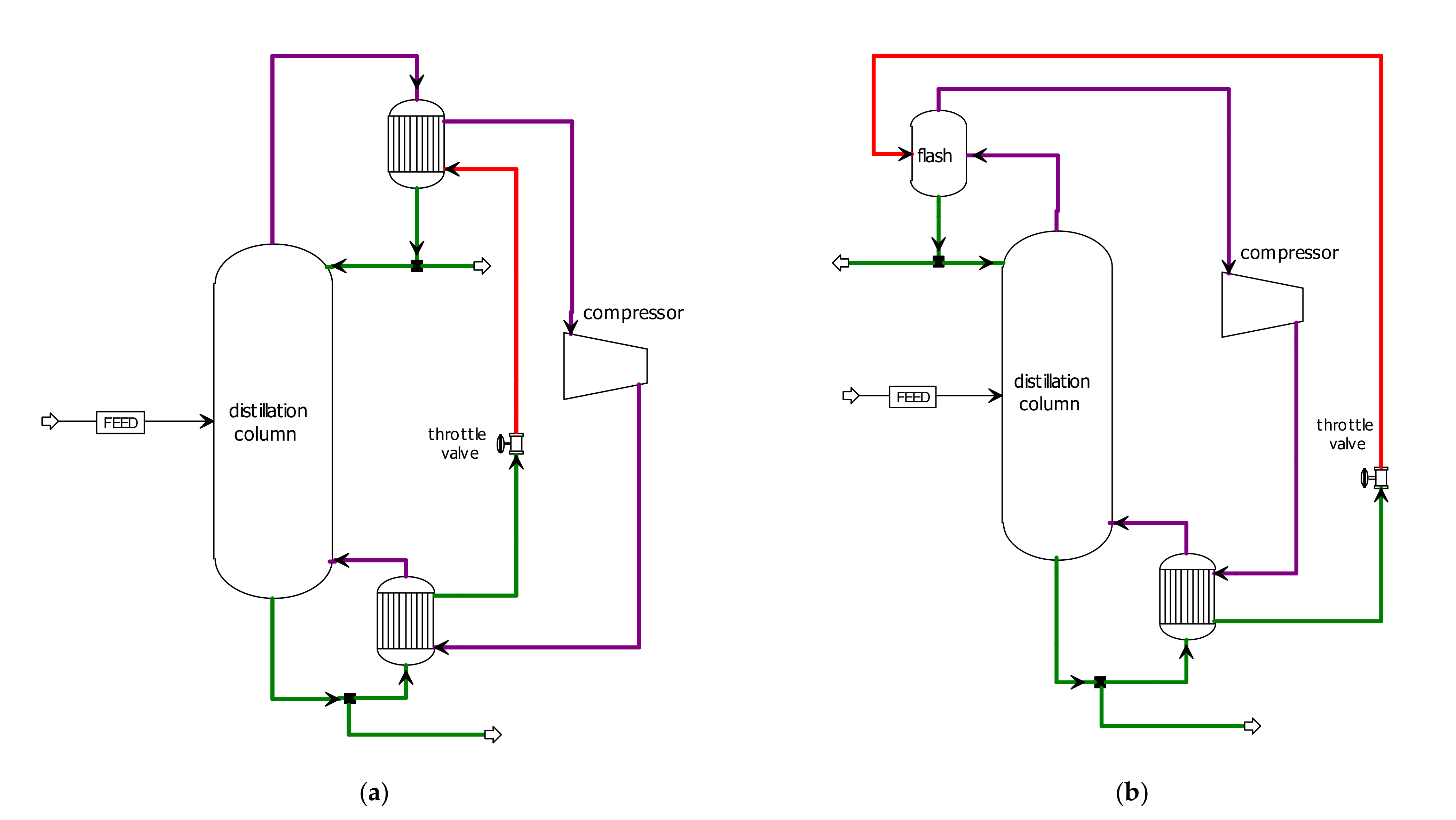
1.2. Heat Pumps Integration
1.3. Current Trends of Heat Pump Application in Separation Processes
- ⮚
- Improving designed ethyl acetate production processes;
- ⮚
- Process integration and intensification using a heat pump;
- ⮚
- Process integration: conventional process and reactive distillation;
- ⮚
- Assessment of three different points of view—energy, economic, and safety aspects.
1.4. Methodology
1.4.1. Sustainability Indicators
2. Process Modeling
2.1. Chemical System Description

2.2. Equipment Model
2.3. Simulation Goals and Design Specifications
3. Simulation Results
3.1. MVRHP in Conventional Process
3.2. MVRHP in RD Column with a Separation Unit
4. Discussion
4.1. Heat Pump Effect on Process Energy Intensity
4.2. Heat pump Effect on Process Economics
4.3. Heat Pump Effect on Chemical Process Safety
4.4. Overall Heat Pump Application Assessment
5. Conclusions
Author Contributions
Funding
Data Availability Statement
Conflicts of Interest
List of Symbols
| A | heat exchanger area m2 |
| C | molar concentration kmol m−3 |
| d | column internal diameter m |
| f | feed stage position |
| H | packed section height m |
| ṁ | mass flow t h−1 |
| ṅ | molar flow kmol h−1 |
| N | number of theoretical stages, total condenser and reboiler are included |
| NR | reactive section stages |
| P | total pressure kPa |
| Q | heat kW |
| condenser duty kW | |
| reboiler duty kW | |
| r | reaction rate kmol m−3 s−1 |
| R | gas constant kJ kmol−1 K−1 |
| R | reflux ratio |
| T | temperature °C |
| T | thermodynamic temperature in Equation (4) K |
| volume flow m3 h−1 | |
| W | compressor required network kW |
| x | molar fraction in the liquid phase |
| reference efficiency of electricity production | |
| reference efficiency of heat production |
Subscripts
| AA | acetic acid |
| C | condenser |
| D | distillate |
| E | electricity |
| EtAc | ethyl acetate |
| EtO | Hethanol |
| F | feed |
| H2O | water |
| Q | heat |
| R | reaction occurrence |
| W | reboiler |
Abbreviations
| AA | acetic acid |
| AOC | annual operation cost |
| ASC | annualized separation costs |
| COP | coefficient of performance |
| CSTR | continuous stirred tank reactor |
| EQ | equilibrium |
| EtAc | ethyl acetate |
| EtOH | ethanol |
| HOC | Hayden–O’Connell equation of state |
| HP | heat pump |
| MVRHP | mechanical vapor recompression heat pump |
| NEQ | non-equilibrium |
| NRTL | non-random two liquids |
| OEC | overall energy consumption kW |
| PES | primary energy savings |
| RD | reactive distillation |
| RDS | reactive distillation with stripper column |
| RDAR | reactive distillation with auxiliary reaction |
| RDWC | reactive distillation with a dividing wall |
| SEC | specific energy consumption kWh t−1EtAc |
| TAC | total annual cost USD year−1 |
| TCC | total capital cost USD |
| TPC | total production cost USD t−1 |
| VL | vapor–liquid |
| VLLE | vapor–liquid–liquid phase equilibria |
Appendix A

Appendix B

| 1 | 2 | 3 | 4 | 5 | 6 | 7 | 8 | 9 | 10 | 11 | 12 | 13 | 14 | 15 | 16 | 17 | |
|---|---|---|---|---|---|---|---|---|---|---|---|---|---|---|---|---|---|
| ṅ [kmol h−1] | 10.00 | 10.00 | 19.88 | 22.64 | 42.52 | 42.52 | 42.52 | 12.65 | 12.65 | 39.86 | 187.78 | 187.78 | 41.21 | 41.21 | 21.21 | 21.21 | 20.00 |
| xH2O | - | - | 0.0869 | - | 0.0407 | 0.2756 | 0.2756 | - | - | 0.2940 | 0.7608 | 0.7608 | 0.1604 | 0.1604 | 0.3114 | 0.3114 | 0.0003 |
| xAA | 1.0000 | - | - | 0.8325 | 0.4433 | 0.2083 | 0.2083 | 0.7000 | 0.7000 | - | - | - | - | - | - | - | - |
| xEtAc | - | - | 0.1301 | 0.1673 | 0.1499 | 0.3848 | 0.3848 | 0.2996 | 0.2996 | 0.5660 | 0.1856 | 0.1856 | 0.7672 | 0.7672 | 0.5487 | 0.5487 | 0.9990 |
| xEtOH | - | 1.0000 | 0.7830 | 0.0002 | 0.3662 | 0.1312 | 0.1312 | 0.0004 | 0.0004 | 0.1400 | 0.0536 | 0.0536 | 0.0724 | 0.0724 | 0.1399 | 0.1399 | 0.0007 |
| T [°C] | 25.00 | 25.00 | 29.38 | 39.64 | 36.98 | 39.01 | 54.24 | 98.20 | 49.01 | 70.02 | 48.97 | 25.00 | 25.00 | 41.79 | 70.02 | 35.00 | 76.83 |
| P [kPa] | 101.3 | 101.3 | 101.3 | 101.3 | 101.3 | 101.3 | 101.3 | 101.3 | 101.3 | 101.3 | 101.3 | 101.3 | 101.3 | 101.3 | 101.3 | 101.3 | 101.3 |
| V [m3 h−1] | 0.56 | 0.58 | 1.19 | 1.44 | 2.65 | 2.66 | 2.72 | 0.95 | 0.88 | 2.90 | 6.71 | 6.50 | 3.37 | 3.45 | 1.51 | 1.43 | 2.12 |
| 18 | 19 | 20 | 21 | 22 | 23 | 24 | 25 a | 26 | 27 | 28 | 29 | 30 | 31 | 32 | 33 | ||
| ṅ [kmol h−1] | 10.00 | 10.00 | 10.00 | 146.57 | 29.31 | 117.26 | 117.26 | 117.26 | 107.38 | 107.38 | 97.37 | 10.00 | 10.00 | 126.69 | 9.87 | 9.87 | |
| xH2O | 0.0003 | 0.0003 | 0.0003 | 0.9296 | 0.9296 | 0.9296 | 0.9296 | 0.9296 | 0.9990 | 0.9990 | 0.9990 | 0.9990 | 0.9990 | 0.9829 | 0.1749 | 0.1749 | |
| xAA | - | - | - | - | - | - | - | - | - | - | - | - | - | - | - | - | |
| xEtAc | 0.9990 | 0.9990 | 0.9990 | 0.0220 | 0.0220 | 0.0220 | 0.0220 | 0.0220 | - | - | - | - | - | 0.0051 | 0.2619 | 0.2619 | |
| xEtOH | 0.0007 | 0.0007 | 0.0007 | 0.0484 | 0.0484 | 0.0484 | 0.0484 | 0.0484 | 0.0010 | 0.0010 | 0.0010 | 0.0010 | 0.0010 | 0.0120 | 0.5632 | 0.5632 | |
| T [°C] | 76.83 | 76.83 | 25.00 | 25.00 | 25.00 | 25.00 | 30.34 | 72.79 | 99.34 | 40.34 | 40.34 | 40.34 | 40.34 | 36.54 | 71.69 | 35.00 | |
| P [kPa] | 101.3 | 101.3 | 101.3 | 101.3 | 101.3 | 101.3 | 101.3 | 101.3 | 101.3 | 101.3 | 101.3 | 101.3 | 101.3 | 101.3 | 101.3 | 101.3 | |
| V [m3 h−1] | 1.06 | 1.06 | 0.98 | 3.18 | 0.64 | 2.55 | 2.56 | 59.33 a | 2.11 | 1.98 | 1.80 | 0.00 | 0.18 | 2.43 | 0.65 | 0.61 |
| 34 | 35 | 36 a | 37 a | 38 a | 39 b | 40 | 41 | 42 | 43 | 44 | |
|---|---|---|---|---|---|---|---|---|---|---|---|
| ṅ [kmol h−1] | 172.89 | 172.89 | 152.77 | 136.92 | 154.20 | 154.20 | 154.20 | 154.20 | 154.20 | 137.05 | 115.84 |
| xH2O | 0.0009 | 0.0009 | 0.0009 | 0.3131 | 0.3051 | 0.3051 | 0.3051 | 0.3051 | 0.3051 | 0.3128 | 0.3131 |
| xAA | 0.0000 | 0.0000 | 0.0000 | 0.0000 | 0.0000 | 0.0000 | 0.0000 | 0.0000 | 0.0000 | 0.0000 | 0.0000 |
| xEtAc | 0.9980 | 0.9980 | 0.9978 | 0.5461 | 0.5525 | 0.5525 | 0.5525 | 0.5525 | 0.5525 | 0.5465 | 0.5461 |
| xEtOH | 0.0011 | 0.0011 | 0.0012 | 0.1408 | 0.1425 | 0.1425 | 0.1425 | 0.1425 | 0.1425 | 0.1407 | 0.1408 |
| T [°C] | 78.80 | 78.83 | 78.83 | 71.95 | 71.40 | 108.73 | 96.48 | 94.77 | 71.94 | 71.41 | 71.41 |
| vapor fraction | 0 | 0.88 | 1 | 1 | 1 | 1 | 0.05 | 0 | 0.11 | 0 | 0 |
| P [kPa] | 101.3 | 101.3 | 101.3 | 101.3 | 101.3 | 250.0 | 240.0 | 240.0 | 101.3 | 101.3 | 101.3 |
| V [m3 h−1] | 18.38 | 3995.23 | 3993.11 a | 3605.21 a | 4133.42 a | 1866.80 b | 105.61 | 11.54 | 440.32 | 9.77 | 8.26 |
| 1 | 2 | 3 | 4 | 5 | 6 | 7 | 8 | 9 | 10 | 11 | 12 | 13 | 14 | |
|---|---|---|---|---|---|---|---|---|---|---|---|---|---|---|
| ṅ[kmol h−1] | 10.00 | 10.00 | 20.94 | 7.72 | 40.60 | 30.59 | 30.59 | 30.59 | 19.66 | 19.66 | 10.00 | 10.00 | 69.62 | 77.34 |
| xH2O | - | - | 0.2666 | 0.7918 | 0.2165 | 0.2873 | 0.2873 | 0.2873 | 0.1632 | 0.1632 | 0.0002 | 0.0002 | 0.9227 | 0.9096 |
| xAA | 1.0000 | - | - | - | - | - | - | - | - | - | - | - | - | - |
| xEtAc | - | - | 0.5536 | - | 0.6515 | 0.5378 | 0.5378 | 0.5378 | 0.7558 | 0.7558 | 0.9990 | 0.9990 | 0.0229 | 0.0206 |
| xEtOH | - | 1.0000 | 0.1798 | 0.2082 | 0.1320 | 0.1749 | 0.1749 | 0.1749 | 0.0811 | 0.0811 | 0.0008 | 0.0008 | 0.0544 | 0.0697 |
| T [°C] | 25.00 | 25.00 | 70.02 | 82.47 | 64.47 | 70.01 | 45.84 | 25.00 | 25.00 | 60.00 | 76.84 | 25.00 | 25.00 | 31.20 |
| P [kPa] | 101.3 | 101.3 | 101.3 | 101.3 | 101.3 | 101.3 | 101.3 | 101.3 | 101.3 | 101.3 | 101.3 | 101.3 | 101.3 | 101.3 |
| V [m3 h−1] | 0.56 | 0.58 | 1.54 | 0.22 | 3.21 | 2.20 | 2.12 | 2.06 | 1.59 | 1.68 | 1.06 | 0.98 | 1.53 | 1.75 |
| 15 a | 16 | 17 | 18 | 19 | 20 | 21 | 22 | |||||||
| ṅ [kmol h−1] | 77.34 | 8.66 | 18.66 | 68.70 | 68.70 | 68.70 | 58.67 | 10.02 | ||||||
| xH2O | 0.9096 | 0.1958 | 0.0909 | 0.9995 | 0.9995 | 0.9995 | 0.9995 | 0.9995 | ||||||
| xAA | - | - | - | - | - | - | - | - | ||||||
| xEtAc | 0.0206 | 0.1842 | 0.0855 | - | - | - | - | - | ||||||
| xEtOH | 0.0698 | 0.6200 | 0.8236 | 0.0005 | 0.0005 | 0.0005 | 0.0005 | 0.0005 | ||||||
| T [°C] | 72.04 | 72.65 | 47.88 | 99.50 | 45.00 | 25.00 | 25.00 | 25.00 | ||||||
| P [kPa] | 101.3 | 101.3 | 101.3 | 101.3 | 101.3 | 101.3 | 101.3 | 101.3 | ||||||
| V [m3 h−1] | 19.65 a | 0.53 | 1.11 | 1.35 | 1.27 | 1.25 | 1.06 | 0.18 |
| 23 a | 24 | 25 | 26 a | 27 b | 28 | 29 | 30 | 31 | 32 | 33 a | |
|---|---|---|---|---|---|---|---|---|---|---|---|
| ṅ [kmol h−1] | 181.00 | 181.00 | 150.41 | 201.72 | 201.72 | 201.72 | 201.72 | 201.72 | 207.27 | 207.27 | 197.98 |
| xH2O | 0.2393 | 0.2393 | 0.2393 | 0.2559 | 0.2559 | 0.2559 | 0.2559 | 0.2559 | 0.0000 | 0.0000 | 0.0000 |
| xAA | - | - | - | - | - | - | - | - | - | - | - |
| xEtAc | 0.6154 | 0.6154 | 0.6154 | 0.6137 | 0.6137 | 0.6137 | 0.6137 | 0.6137 | 0.9973 | 0.9973 | 0.9972 |
| xEtOH | 0.1453 | 0.1453 | 0.1453 | 0.1304 | 0.1304 | 0.1304 | 0.1304 | 0.1304 | 0.0027 | 0.0027 | 0.0028 |
| T [°C] | 71.68 | 70.91 | 70.93 | 70.91 | 106.47 | 95.28 | 93.62 | 71.38 | 78.21 | 78.24 | 78.24 |
| vapor fraction | 1 | 0 | 0 | 1 | 1 | 0.075 | 0 | 0.101 | 0 | 0.96 | 1 |
| P [kPa] | 101.3 | 101.3 | 101.3 | 101.3 | 250.0 | 240.0 | 240.0 | 101.3 | 101.3 | 101.3 | 101.3 |
| V [m3 h−1] | 4724.95 a | 14.02 | 11.65 | 5390.84 a | 2416.37 b | 199.31 | 16.07 | 548.38 | 22.02 | 5268.56 | 5267.57 a |
| Conventional Process (Figure 2) | Conventional Process with an MVRHP (Figure 4) | RD Column with a Separation Unit (Figure 3) | RD Column with a Separation Unit and an MVRHP (Figure 6) | |||||
|---|---|---|---|---|---|---|---|---|
| Equipment Cost | Installed Cost | Equipment Cost | Installed Cost | Equipment Cost | Installed Cost | Equipment Cost | Installed Cost | |
| Item | [103 USD] | [103 USD] | [103 USD] | [103 USD] | [103 USD] | [103 USD] | [103 USD] | [103 USD] |
| CSTR | 173.7 | 334.3 | 173.7 | 334.3 | - | - | - | - |
| C1/C1-RD | 620.7 | 1147.2 | 620.7 | 1147.2 | 680.5 | 1214.0 | 680.5 | 1214.0 |
| C2 | 594.5 | 1138.1 | 543.2 a | 864.2 a | 610.6 | 1185.2 | 551.9 a | 881.2 a |
| K1 | - | - | 344.7 | 551.5 | - | - | 376.3 | 602.1 |
| C3 | 172.6 | 564.0 | 172.6 | 564.0 | 148.0 | 487.8 | 148.0 | 487.8 |
| DEC | 16.1 | 108.9 | 16.1 | 108.9 | 16.1 | 108.9 | 16.1 | 108.9 |
| EX1 | 8.5 | 53.0 | 8.5 | 53.0 | 8.7 | 59.1 | 8.7 | 59.1 |
| EX2 | 39.3 | 120.0 | 39.3 | 120.0 | 19.3 | 85.4 | 19.3 | 85.4 |
| EX3 | 8.7 | 59.1 | 8.7 | 59.1 | 9.9 | 62.6 | 9.9 | 62.6 |
| EX4 | 8.5 | 45.7 | 8.5 | 45.7 | 14.3 | 70.7 | 14.3 | 70.7 |
| EX5 | 11.0 | 63.9 | 11.0 | 63.9 | 10.9 | 60.8 | 10.9 | 60.8 |
| EX6 | 8.5 | 45.7 | 8.5 | 45.7 | - | - | 42.4 b | 127.0 b |
| EX7 | 10.5 | 60.3 | 10.5 | 60.3 | - | - | 37.7 | 93.4 |
| EX8 | - | - | 34.8 b | 116.1 b | - | - | - | - |
| EX9 | - | - | 35.9 | 87.6 | - | - | - | - |
| Sum | 1672.6 | 3740.2 | 2036.7 | 4221.5 | 1518.3 | 3334.5 | 1916.0 | 3853.0 |
References
- Riemenschneider, W.; Bolt, H.M. Esters, Organic. In Ullmann’s Encyclopedia of Industrial Chemistry; Wiley-VCH Verlag GmbH & Co. KGaA: Weinheim, Germany, 2012. [Google Scholar] [CrossRef]
- Srinivasan, R.; Nhan, N.T. A statistical approach for evaluating inherent benign-ness of chemical process routes in early design stages. Process Saf. Environ. Prot. 2008, 86, 163–174. [Google Scholar] [CrossRef]
- Li, C.; Duan, C.; Fang, J.; Li, H. Process intensification and energy saving of reactive distillation for production of ester compounds. Chin. J. Chem. Eng. 2019, 27, 1307–1323. [Google Scholar] [CrossRef]
- Santaella, M.A.; Orjuela, A.; Narváez, P.C. Comparison of different reactive distillation schemes for ethyl acetate production using sustainability indicators. Chem. Eng. Process. Process Intensif. 2015, 96, 1–13. [Google Scholar] [CrossRef]
- Šulgan, B.; Labovský, J.; Labovská, Z. Multi-Aspect Comparison of Ethyl Acetate Production Pathways: Reactive Distillation Process Integration and Intensification via Mechanical and Chemical Approach. Processes 2020, 8, 1618. [Google Scholar] [CrossRef]
- Toth, A.J. Comprehensive evaluation and comparison of advanced separation methods on the separation of ethyl acetate-ethanol-water highly non-ideal mixture. Sep. Purif. Technol. 2019, 224, 490–508. [Google Scholar] [CrossRef]
- Kiss, A.A.; Jobson, M. Taking Reactive Distillation to the Next Level of Process Intensification. Chem. Eng. Trans. 2018, 69, 553–558. [Google Scholar] [CrossRef]
- Segovia-Hernández, J.G.; Hernández, S.; Bonilla Petriciolet, A. Reactive distillation: A review of optimal design using deterministic and stochastic techniques. Chem. Eng. Process. Process Intensif. 2015, 97, 134–143. [Google Scholar] [CrossRef]
- Hu, S.; Zhang, B.; Hou, X.; Li, D.; Chen, Q. Design and simulation of an entrainer-enhanced ethyl acetate reactive distillation process. Chem. Eng. Process. Process Intensif. 2011, 50, 1252–1265. [Google Scholar] [CrossRef]
- Tavan, Y.; Behbahani, R.M.; Hosseini, S.H. A novel intensified reactive distillation process to produce pure ethyl acetate in one column—Part I: Parametric study. Chem. Eng. Process. Process Intensif. 2013, 73, 81–86. [Google Scholar] [CrossRef]
- Xie, J.; Li, C.; Peng, F.; Dong, L.; Ma, S. Experimental and simulation of the reactive dividing wall column based on ethyl acetate synthesis. Chin. J. Chem. Eng. 2018, 26, 1468–1476. [Google Scholar] [CrossRef]
- Calvar, N.; González, B.; Dominguez, A. Esterification of acetic acid with ethanol: Reaction kinetics and operation in a packed bed reactive distillation column. Chem. Eng. Process. Process Intensif. 2007, 46, 1317–1323. [Google Scholar] [CrossRef]
- Harmsen, G.J. Reactive distillation: The front-runner of industrial process intensification. Chem. Eng. Process. Process Intensif. 2007, 46, 774–780. [Google Scholar] [CrossRef] [Green Version]
- Kiss, A.A. Energy Efficient Distillation Powered By Heat Pumps Upgrading Low Quality Energy To Drive the Reboiler of the Column. NPT Procestechnol. 2014, 2, 15–17. [Google Scholar]
- Jana, A.K. Advances in heat pump assisted distillation column: A review. Energy Convers. Manag. 2014, 77, 287–297. [Google Scholar] [CrossRef]
- Joda, F.; Ahmadi, F. Exergoeconomic analysis of conventional and using reactive distillation biodiesel production scenarios thermally integrated with a combined power plan. Renew. Energy 2019, 132, 898–910. [Google Scholar] [CrossRef]
- Feng, S.; Ye, Q.; Xia, H.; Li, R.; Suo, X. Integrating a vapor recompression heat pump into a lower partitioned reactive dividing-wall column for better energy-saving performance. Chem. Eng. Res. Des. 2017, 125, 204–213. [Google Scholar] [CrossRef]
- Shi, L.; Wang, S.J.; Huang, K.; Wong, D.S.H.; Yuan, Y.; Chen, H.; Zhang, L.; Wang, S. Intensifying reactive dividing-wall distillation processes via vapor recompression heat pump. J. Taiwan Inst. Chem. Eng. 2017, 78, 8–19. [Google Scholar] [CrossRef]
- Liu, Y.; Zhai, J.; Li, L.; Sun, L.; Zhai, C. Heat pump assisted reactive and azeotropic distillations in dividing wall columns. Chem. Eng. Process. Process Intensif. 2015, 95, 289–301. [Google Scholar] [CrossRef]
- Christopher, C.C.E.; Dutta, A.; Farooq, S.; Karimi, I.A. Process Synthesis and Optimization of Propylene/Propane Separation Using Vapor Recompression and Self-Heat Recuperation. Ind. Eng. Chem. Res. 2017, 56, 14557–14564. [Google Scholar] [CrossRef]
- Feng, Z.; Shen, W.; Rangaiah, G.P.; Dong, L. Design and control of vapor recompression assisted extractive distillation for separating n-hexane and ethyl acetate. Sep. Purif. Technol. 2020, 240, 116655. [Google Scholar] [CrossRef]
- Dai, M.; Yang, F.; Zhang, Z.; Liu, G.; Feng, X. Energetic, economic and environmental (3E) multi-objective optimization of the back-end separation of ethylene plant based on adaptive surrogate model. J. Clean. Prod. 2021, 310, 127426. [Google Scholar] [CrossRef]
- Sharon, H. Energy, exergy, environmental benefits and economic aspects of novel hybrid solar still for sustainable water distillation. Process Saf. Environ. Prot. 2021, 150, 1–21. [Google Scholar] [CrossRef]
- Klauzner, P.S.; Rudakov, D.G.; Anokhina, E.A.; Timoshenko, A.V. Use of Partially Thermally Coupled Distillation Systems and Heat Pumps for Reducing the Energy Consumption in the Extractive Distillation of an Isobutanol-Isobutyl Acetate Mixture Using Dimethylformamide. Theor. Found. Chem. Eng. 2020, 54, 397–406. [Google Scholar] [CrossRef]
- Shi, X.; Zhu, X.; Zhao, X.; Zhang, Z. Performance evaluation of different extractive distillation processes for separating ethanol/tert-butanol/water mixture. Process Saf. Environ. Prot. 2020, 137, 246–260. [Google Scholar] [CrossRef]
- Zhang, Q.; Yang, S.; Shi, P.; Hou, W.; Zeng, A.; Ma, Y.; Yuan, X. Economically and thermodynamically efficient heat pump-assisted side-stream pressure-swing distillation arrangement for separating a maximum-boiling azeotrope. Appl. Therm. Eng. 2019, 173, 115228. [Google Scholar] [CrossRef]
- Cong, H.; Murphy, J.P.; Li, X.; Li, H.; Gao, X. Feasibility Evaluation of a Novel Middle Vapor Recompression Distillation Column. Ind. Eng. Chem. Res. 2018, 57, 6317–6329. [Google Scholar] [CrossRef]
- Van Duc Long, N.; Han, T.H.; Lee, D.Y.; Park, S.Y.; Hwang, B.B.; Lee, M. Enhancement of a R-410A reclamation process using various heat-pump-assisted distillation configurations. Energies 2019, 12, 3776. [Google Scholar] [CrossRef] [Green Version]
- Duan, C.; Li, C. Novel energy-saving methods to improve the three-column extractive distillation process for separating ethyl acetate and ethanol using furfural. Sep. Purif. Technol. 2021, 272, 118887. [Google Scholar] [CrossRef]
- Shi, T.; Chun, W.; Yang, A.; Su, Y.; Jin, S.; Ren, J.; Shen, W. Optimization and control of energy saving side-stream extractive distillation with heat integration for separating ethyl acetate-ethanol azeotrope. Chem. Eng. Sci. 2020, 215, 115373. [Google Scholar] [CrossRef]
- Parmar, K.K.; Parmar, K.K.; Padmavathi, G.; Dash, S.K. Energy reduction and improved product recovery with enhanced safety of industrial scale propane-propylene separation process. Int. J. Energy Res. 2020, 44, 12630–12638. [Google Scholar] [CrossRef]
- Ifaei, P.; Safder, U.; Yoo, C.K. Multi-scale smart management of integrated energy systems, Part 1: Energy, economic, environmental, exergy, risk (4ER) and water-exergy nexus analyses. Energy Convers. Manag. 2019, 197, 111851. [Google Scholar] [CrossRef]
- Official Journal of the European Union. Available online: https://eur-lex.europa.eu/LexUriServ/LexUriServ.do?uri=OJ:L:2007:032:0183:0188:SK:PDF (accessed on 17 May 2021).
- Couper, J.R.; Hertz, D.W.; Smith, F.L. Process Economics. In Perry’s Chemical Engineers’ Handbook; Green, D.W., Perry, R.H., Eds.; McGraw-Hill: New York, NY, USA, 2007; Volume 848. [Google Scholar]
- The Center for Chemical Process Safety. Guidelines for Chemical Process. Quantitative Risk Analysis; American Institute of Chemical Engineers: New York, NY, USA, 1989. [Google Scholar]
- Trofimova, M.; Sadaev, A.; Samarov, A.; Golikova, A.; Tsvetov, N.; Toikka, M.; Toikka, A. Liquid-liquid equilibrium of acetic acid-ethanol-ethyl acetate-water quaternary system: Data review and new results at 323.15 K and 333.15 K. Fluid Phase Equilib. 2020, 503, 112321. [Google Scholar] [CrossRef]
- Singh, D.; Gupta, R.K.; Kumar, V. Simulation of a plant scale reactive distillation column for esterification of acetic acid. Comput. Chem. Eng. 2015, 73, 70–81. [Google Scholar] [CrossRef]
- Pavlíček, J.; Bogdanić, G.; Wichterle, I. Vapour–liquid and chemical equilibria in the ethyl ethanoate+ethanol+propyl ethanoate+propanol system accompanied with transesterification reaction. Fluid Phase Equilib. 2012, 328, 61–68. [Google Scholar] [CrossRef]
- ASPEN Technology. Aspen Plus®: Aspen Plus User Guide; Version 12.0; Aspen Technology Inc.: Cambridge, MA, USA, 2000. [Google Scholar]
- Hayden, J.G.; O’Connell, J.P. A Generalized Method for Predicting Second Virial Coefficients. Ind. Eng. Chem. Process Des. Dev. 1975, 14, 209–216. [Google Scholar] [CrossRef]
- Eilerman, R.G.; Staff, U. Cinnamic Acid, Cinnamaldehyde, and Cinnamyl Alcohol. In Kirk-Othmer Encyclopedia of Chemical Technology; John Wiley & Sons, Inc.: Hoboken, NJ, USA, 2014; pp. 1–11. [Google Scholar]
- GPSA (Gas Processors Supplier Associations) Engineering Data Book; Gas Processors Supplier Associations: Tulsa, OK, USA, 1979.
- Walas, S.M.; Couper, J.R.; Penney, W.R.; Fair, J.R. Chemical Process Equipment: Selection and Design; Elsevier Inc.: Oxford, UK, 2009. [Google Scholar]
- Chembid. Available online: www.chembid.com (accessed on 20 May 2021).
- Molbase. Available online: www.molbase.com (accessed on 20 May 2021).
- Löser, C.; Urit, T.; Bley, T. Perspectives for the biotechnological production of ethyl acetate by yeasts. Appl. Microbiol. Biotechnol. 2014, 98, 5397–5415. [Google Scholar] [CrossRef] [PubMed]
- Hamels, S. CO2 Intensities and Primary Energy Factors in the Future European Electricity System. Energies 2021, 14, 2165. [Google Scholar] [CrossRef]
- Vílchez, J.A.; Espejo, V.; Casal, J. Generic event trees and probabilities for the release of different types of hazardous materials. J. Loss Prev. Process Ind. 2011, 24, 281–287. [Google Scholar] [CrossRef]


| Study | System | Modeling | Objectives | Results, Comparison to Conventional Process | Reference |
|---|---|---|---|---|---|
| Klauzner et al. (2020) | Extractive distillation of isobutanol-isobutyl acetate | Aspen Plus V9 | TAC, cost of energy carriers | Energy carrier costs reduced by 56%, TAC reduced by 30.7% | [24] |
| Shi et al. (2020) | Extractive distillation of Ethanol-tert butanol-water | Aspen Plus V10 | Payback period, TAC, CO2 emissions, total emissions | CO2 emissions decreased by 47%, higher TAC | [25] |
| Zhang et al. (2020) | Isopropanol-butanol-ethanol separation from fermentation broth | Aspen Plus V10 | TAC, CO2 emissions | Annual operation cost decrease by 44%, 30.5% reduction in CO2 emissions | [26] |
| Cong et al. (2018) | Model binary and ternary mixtures | Aspen Plus V7.2 | TAC, annual operating cost (AOC) | TAC and AOC savings with different configurations | [27] |
| Christopher et al. (2017) | Propane-propylene | Aspen Hysys + Matlab | Energy consumption, annualized separation costs (ASC) | Best configuration achieved energy consumption savings of 45% and ASC saving of 20% | [20] |
| Parmar et al. (2020) | Propane-propylene splitting in an Ethylene plant | Aspen Plus | Energy consumption, propylene recovery, process safety | Energy consumption reduction by 68%, propylene recovery increase by 3%, process safety evaluated from experience | [31] |
| Long et al. (2019) | Separation of R410A and R22 | Aspen Hysys V10 | AOC, CO2 emissions | AOC savings of up to 60% and CO2 emissions saving of up to 58% in the best configuration | [28] |
| Feng et al. (2020) | Extractive distillation of n-hexane and ethyl acetate | Aspen Plus V8.8 + Matlab 2019a | TAC, operating costs, thermal efficiency | Operating costs reduction by over 90%, TAC reduction by 7%, thermal efficiency increased by over 9% | [21] |
| Duan and Li (2021) | Extractive distillation of ethanol and ethyl acetate | Aspen Plus V11 | TAC, CO2 emissions | 55% reduction on TAC and 66% reduction in CO2 emissions possible with best configuration | [29] |
| Shi et al. (2020) | Extractive distillation of ethanol and ethyl acetate | Genetic Algorithm | TAC, CO2 emissions, dynamic control simulation | TAC can be reduced by over 7% and CO2 emissions by over 9% | [30] |
| Conventional Process | RD Column with a Separation Unit | RDS | RDAR | |
|---|---|---|---|---|
| number of main equipmenta | 5 | 4 | 2 | 1 |
| number of heat exchangers | 7 | 5 | 2 | 2 |
| process integration | base process | reactive distillation | reactive distillation stripper column | auxiliary reaction fully integrated process |
| heat integration | yes | yes | thermal coupling | chemical reaction synergy |
| benefits |
|
|
|
|
| drawbacks |
|
|
|
|
| Conventional Process | Conventional Process with an MVRHP | RD Column with a Separation Unit | RD Column with a Separation Unit and an MVRHP | |||||
|---|---|---|---|---|---|---|---|---|
| (Figure 2) | (Figure 4) | (Figure 3) | (Figure 6) | |||||
| Equipment | [kW] | [kW] | [kW] | [kW] | [kW] | [kW] | [kW] | [kW] |
| C1/C1-RD | 1135.23 | 1181.19 | 1135.23 | 1181.19 | 676.69 | 703.86 | 676.69 | 703.86 |
| C2 | 1212.97 | 1267.94 | - | - | 1750.31 | 1759.95 | - | - |
| K1 | - | - | - | 151.67c | - | - | - | 197.34c |
| C3 | 502.97 | 549.35 | 502.97 | 549.35 | 323.10 | 361.93 | 323.10 | 361.93 |
| C4 | 0.85 | - | 0.85 | - | 8.07 | - | 8.07 | - |
| EX1 | 25.01 a | - | 25.01 a | - | 31.04 a | - | 31.04 a | - |
| EX2 | 133.75 | - | 133.75 | - | 28.61 | - | 28.61 | - |
| EX3 | 31.04 a | - | 33.81 a | - | 77.70 a | - | 77.70 a | - |
| EX4 | 13.73 a | - | 13.73 a | - | 27.83 | - | 27.83 | - |
| EX5 | 131.31 a | - | 131.31 a | - | 25.89 | - | 25.89 | - |
| EX6 | 3.10 | - | 3.10 | - | - | - | - | 1763.88a,b |
| EX7 | 25.85 | - | 25.85 | - | - | - | 154.48 | - |
| EX8 | - | - | - | 1359.33a,b | - | - | - | - |
| EX9 | - | - | 81.24 | - | - | - | - | - |
| OEC | 3014.72 | 2998.48 | 1882.99 | 1730.54 | 2840.50 | 2825.74 | 1244.67 | 1065.79 |
| SEC [kWh t−1 EtAc] | 3424.69 | 3406.24 | 2139.06 | 1965.88 | 3226.77 | 3210.01 | 1413.93 | 1210.73 |
| Number of main equipment units | 5 | 5 + K1 | 4 | 4 + K1 | ||||
| Number of heat exchangers | 7 | 9 | 5 | 7 | ||||
| Conventional Process with an MVRHP (Figure 4) | RD Column with a Separation Unit and an MVRHP (Figure 6) | |
|---|---|---|
| COP | 8.36 | 8.92 |
| PES [%] | 79.49 | 80.78 |
| Raw Materials | References | ||
|---|---|---|---|
| EtOH | 800 | USD t1 | [44,45] |
| AA | 400 | USD t−1 | [44] |
| Products | |||
| EtAc | 1300 | USD t1 | [46] |
| Energy | [39,47] | ||
| Electricity | 0.0775 | USD kWh−1 | |
| Cooling water | 0.0317 | USD m−3 | |
| Steam (0.7 MPa) | 0.0179 | USD kg−1 | |
| Conventional Process | Conventional Process with an MVRHP | RD Column with a Separation Unit | RD column with a Separation Unit and an MVRHP | |||||
|---|---|---|---|---|---|---|---|---|
| (Figure 2) | (Figure 4) | (Figure 3) | (Figure 6) | |||||
| Rate | Price [USD h−1] | Rate | Price [USD h−1] | Rate | Price [USD h−1] | Rate | Price [USD h−1] | |
| Electricity [kW] | 104.2 | 8.1 | 351.5 | 27.2 | 58.1 | 4.5 | 345.1 | 26.8 |
| Cooling water [m3 h−1] | 233.1 | 7.4 | 139.3 | 4.4 | 219.4 | 7.0 | 85.0 | 2.7 |
| Steam (0.7 MPa) [kg h−1] | 5220.0 | 93.7 | 3012.7 | 54.1 | 4920.7 | 88.3 | 1856.0 | 33.3 |
| Conventional Process | Conventional Process with an MVRHP | RD Column with a Separation Unit | RD Column with a Separation Unit and an MVRHP | |
|---|---|---|---|---|
| (Figure 2) | (Figure 4) | (Figure 3) | (Figure 6) | |
| Total capital cost [mil. USD] | 9.91 | 11.19 | 8.84 | 10.21 |
| Total installed cost [mil. USD] | 3.74 | 4.22 | 3.33 | 3.85 |
| Total annual cost [mil. USD year−1] | 9.15 | 8.88 | 9.04 | 8.61 |
| Total raw materials cost [mil. USD year−1] | 5.46 | 5.46 | 5.46 | 5.46 |
| Total product sales [mil. USD year−1] | 10.27 | 10.27 | 10.27 | 10.27 |
| Total utilities cost [mil. USD year−1] | 0.89 | 0.70 | 0.81 | 0.51 |
| Pay-back period [year] | 10.86 | 10.02 | 9.19 | 8.13 |
| Total production cost [USD t−1] | 1273.9 | 1264.8 | 1266.1 | 1248.2 |
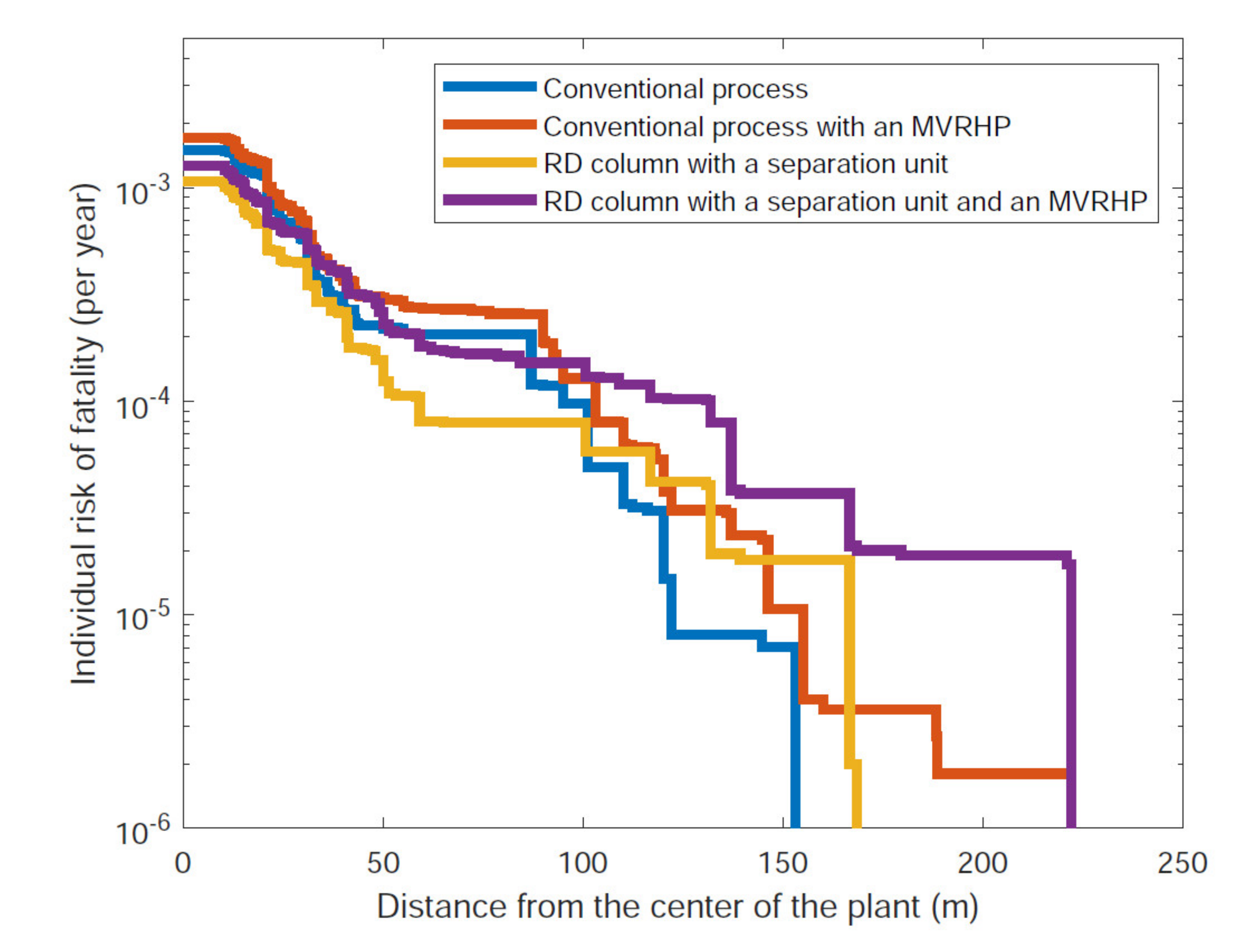
| Individual Risk 10−5 Year−1 | Individual Risk 10−4 Year−1 | |
|---|---|---|
| Distance from the Center [m] | Distance from the Center [m] | |
| Conventional process (Figure 2) | 122 | 95 |
| RD column with separation unit (Figure 3) | 166 | 59 |
| Conventional process with an MVRHP (Figure 4) | 155 | 103 |
| RD column with separation unit and an MVRHP (Figure 6) | 222 | 131 |
Publisher’s Note: MDPI stays neutral with regard to jurisdictional claims in published maps and institutional affiliations. |
© 2021 by the authors. Licensee MDPI, Basel, Switzerland. This article is an open access article distributed under the terms and conditions of the Creative Commons Attribution (CC BY) license (https://creativecommons.org/licenses/by/4.0/).
Share and Cite
Šulgan, B.; Labovský, J.; Variny, M.; Labovská, Z. Multi-Objective Assessment of Heat Pump-Assisted Ethyl Acetate Production. Processes 2021, 9, 1380. https://doi.org/10.3390/pr9081380
Šulgan B, Labovský J, Variny M, Labovská Z. Multi-Objective Assessment of Heat Pump-Assisted Ethyl Acetate Production. Processes. 2021; 9(8):1380. https://doi.org/10.3390/pr9081380
Chicago/Turabian StyleŠulgan, Branislav, Juraj Labovský, Miroslav Variny, and Zuzana Labovská. 2021. "Multi-Objective Assessment of Heat Pump-Assisted Ethyl Acetate Production" Processes 9, no. 8: 1380. https://doi.org/10.3390/pr9081380
APA StyleŠulgan, B., Labovský, J., Variny, M., & Labovská, Z. (2021). Multi-Objective Assessment of Heat Pump-Assisted Ethyl Acetate Production. Processes, 9(8), 1380. https://doi.org/10.3390/pr9081380