Article

Enhancing Recovery of Ultra-Fine Magnetite from Low-Iron-Grade Cyanidation Tailings by Optimizing Flow Field Parameters of Low-Intensity Magnetic Separation (LIMS)

1
Faculty of Land Resource Engineering, Kunming University of Science and Technology, Kunming 650093, China
2
Yunnan Gold Mining Group Co., Ltd., Kunming 650200, China
*
Authors to whom correspondence should be addressed.
Separations 2024, 11(4), 120; https://doi.org/10.3390/separations11040120
Submission received: 3 March 2024 / Revised: 2 April 2024 / Accepted: 7 April 2024 / Published: 16 April 2024
(This article belongs to the Special Issue Application of Magnetic Separation Technology in Green Production)

Abstract

:
The characteristics of iron minerals in cyanidation tailings with a low iron grade were determined via chemical composition analysis, iron phase analysis, and mineral liberation analysis (MLA). The results showed that the cyanidation tailings contained 15.68% iron, mainly occurring in the form of magnetite (19.66%) and limonite (79.91%), in which 16.52% magnetite and 65.90% limonite particles were fully liberated. Most ultra-fine magnetite grains were adjacent and wrapped with limonite to form complex intergrowths, which resulted in low-efficiency magnetite recovery in low-intensity magnetic separation (LIMS) and adversely affected the downstream high-gradient magnetic separation (HGMS) process. Thus, in this work, the optimization of the flow field was proposed to enhance the separation of ultra-fine magnetite from the cyanidation tailings using pilot-scale LIMS separation, and the controllable parameters (including feed flow, separation gap, drum rotating speed, and solid weight) affecting ultra-fine magnetite capture were investigated. Under optimized conditions, a high-grade magnetite concentrate assaying 63.31% Fe with 86.46% magnetite recovery was produced, which, respectively, increased by 0.76% and 15.22%, compared with those obtained from industrial production. In addition, from the flow dynamics simulation, it was found that the magnetite particles in the −6 µm ultra-fine fraction were lost much more easily than those of coarser fractions due to the relatively enhanced hydrodynamic drag force acting on the particles compared with the magnetic force. However, this loss would be effectively reduced with the regulation and control of the flow field. The iron recoveries in the −16~+6 µm and −6 µm fractions of magnetite concentrate increased by 3.66% and 4.42%, respectively, under optimized hydrodynamic conditions. This research outcome provides a valuable reference for the economic and effective utilization of iron resources from such solid wastes.

1. Introduction

Although China’s proven iron reserves rank fifth in the world, more than half of the iron resources are low quality and characterized as low iron grade, with complex chemical components and iron materials of ultra-fine grain size disseminated in the ore, which often results in a high level of difficulty and low efficiency in concentrating iron minerals [1]. Due to the relatively low price of steel, the mineral process used for treating low-quality iron ores must be adequately economical and effective. However, the current main technology often has low efficiency for low-quality iron resources, and, thus, many iron ore concentration plants often suspend production due to economic losses. Correspondingly, China confronts the challenge of an excessively low domestic self-sufficiency proportion of approximately 25% for iron concentrate [2].
About 90% of gold is extracted via the cyanidation leaching process due to its advantages of excellent selectivity, maturity, and low cost, and, thus, billions of tons of cyanidation tailings are produced in China. Such cyanidation tailings are a kind of hazardous solid waste, and they commonly contain abundant iron values, such as magnetite, hematite, and limonite. However, the iron mineral particles are mainly distributed in the tailings at an ultra-fine size, which is attributed to the fact that the cyanidation leaching process requires ultra-fine grinding to ensure high leaching efficiency for gold and silver in the magnetite lattice [3]. At present, magnetic separation is a commonly used method for enriching and recovering iron minerals from various iron resources, as it has the advantages of a large processing capacity, a low operation cost, high applicability, and environmental friendliness. Commonly, low-intensity magnetic separation (LIMS) and high-gradient magnetic separation (HGMS) are widely used to recover magnetite and weakly magnetic iron minerals, respectively, but in conventional magnetic separation, especially LIMS, it is easy to lose ultra-fine iron mineral particles (<20 µm), because it does not generate a gradient magnetic field [4]. Such an outcome seriously and adversely affects the subsequent HGMS efficiency [5,6]. Namely, the rod matrix of the HGMS separator is easily clogged with magnetite, reducing its capture efficiency for weakly magnetic iron minerals and its continuity of industrial running. Therefore, the recovery of ultra-fine magnetite at high effectiveness in the LIMS process is a key step for utilizing iron’s value from the cyanidation tailings.
In the past few decades, many studies have been performed to enhance ultra-fine magnetite recovery, mainly including increasing the magnetic induction of LIMS, stage grinding and stage separation, and assisting flocculation and reverse flotation. Increasing magnetic induction can directly and effectively improve the capture of fine-grained magnetite in the LIMS process [7], but it has low feasibility in practice, as it dramatically increases the difficulty of concentrate unloading; meanwhile, the quality of the concentrate obtained at high magnetic induction is often substandard for the downstream steelmaking process. The LIMS process, i.e., magnetic roughing of coarse particles and discarding tailings, rough concentrate regrinding, and two stages of cleaning separation, was proposed [8,9] for improving the separation of iron resources containing ultra-fine magnetite. These studies have verified that the stage grinding process can effectively improve the recovery of ultra-fine magnetite from the original resources economically. However, the stage grinding process is not suitable for treating cyanidation tailings because such tailings are already muddy [10]. In addition, macromolecular organic polymers have been developed for flocculating ultra-fine magnetite particles to assist the magnetic separation enrichment or for reverse flotation collection [11,12,13]. However, the applications of reverse flotation collectors are rather restricted as a result of their enormous dosages and costs in numerous concentration plants. In addition, a highly selective collector is often difficult to achieve. Namely, a low concentration of the collector is not effective in removing gangue during reverse flotation, whereas a high amount of magnetite is lost into the tailings at high concentrations of collectors. Correspondingly, there are very few flocculating agents with high selectivity and a low price for practical applications.
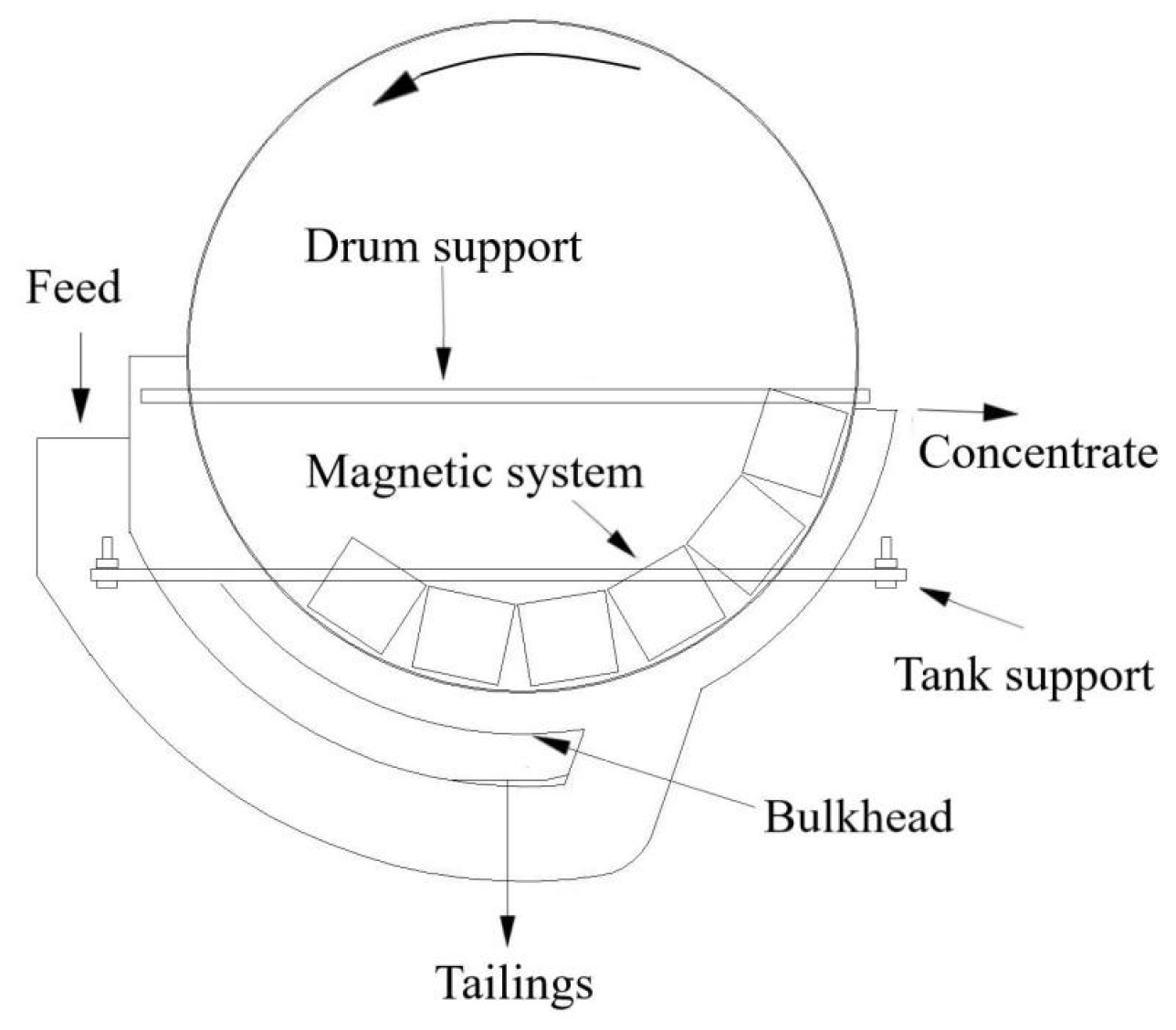
LIMS is still the most proposed technology for economically and effectively recovering ultra-fine magnetite from low-iron-grade resources. Magnetic system investigations have been widely reported because it is the key component of LIMS, determining the separation performance. Generally, an attempt should be made to improve the selective capture of magnetic grains by appropriately increasing the number of magnetic poles; that is, the number of magnetic reversals of the magnetic grains in the separation zone should be increased. If the purpose is to improve the quantity of captured grains, an appropriate reduction in the number of magnetic poles or an increase in the magnetic wrap angle is commonly required to ensure the recovery of magnetic grains [14]. In addition, the acting depth of the magnetic field is another factor that affects the magnetic capture performance of LIMS [15].
Although the design and operation of LIMS are rather simple and direct, understanding the LIMS process performance from a fundamental point of view still remains puzzling due to a number of complex factors involved in the separation. In addition to the magnetic force, the multiple hydrodynamic competing forces generated in the separating zone of the LIMS separator are also key factors affecting the separation performance of ultra-fine iron minerals. In recent years, computational dynamics simulations have been gradually employed to investigate the behavior of iron minerals in the LIMS process. Guiral-Vega et al. conducted simulations and analyses on the forces acting on particles in drum-type wet LIMS [16,17]. These studies provide important background and guidance for LIMS fundamentals.
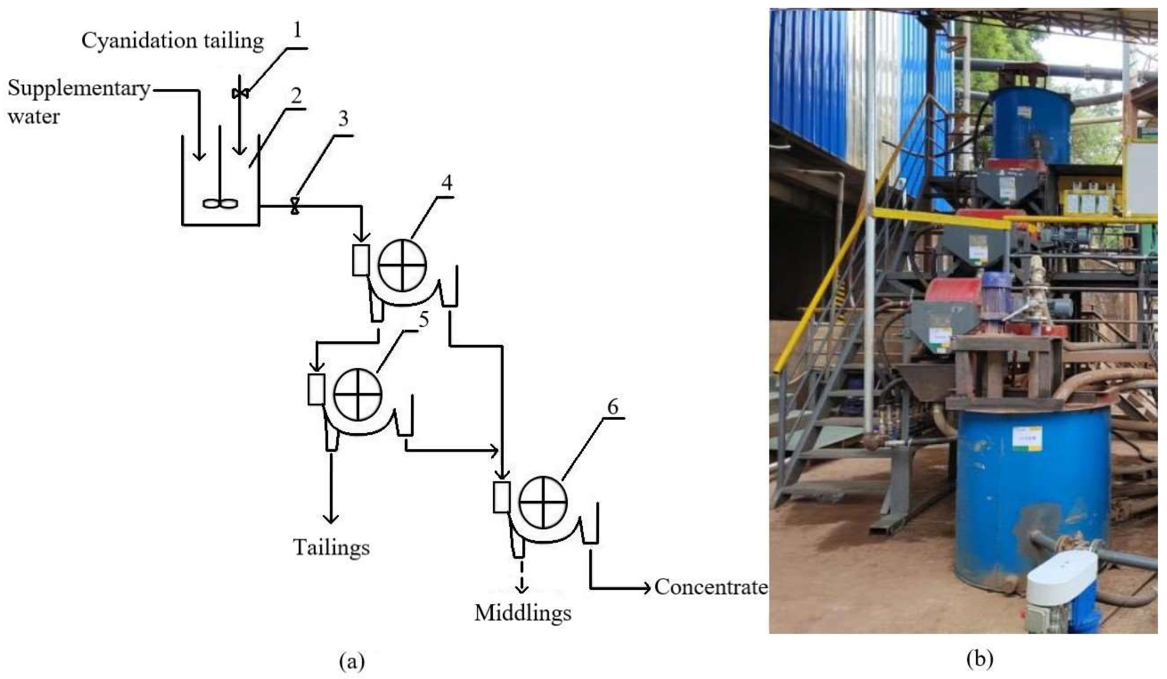
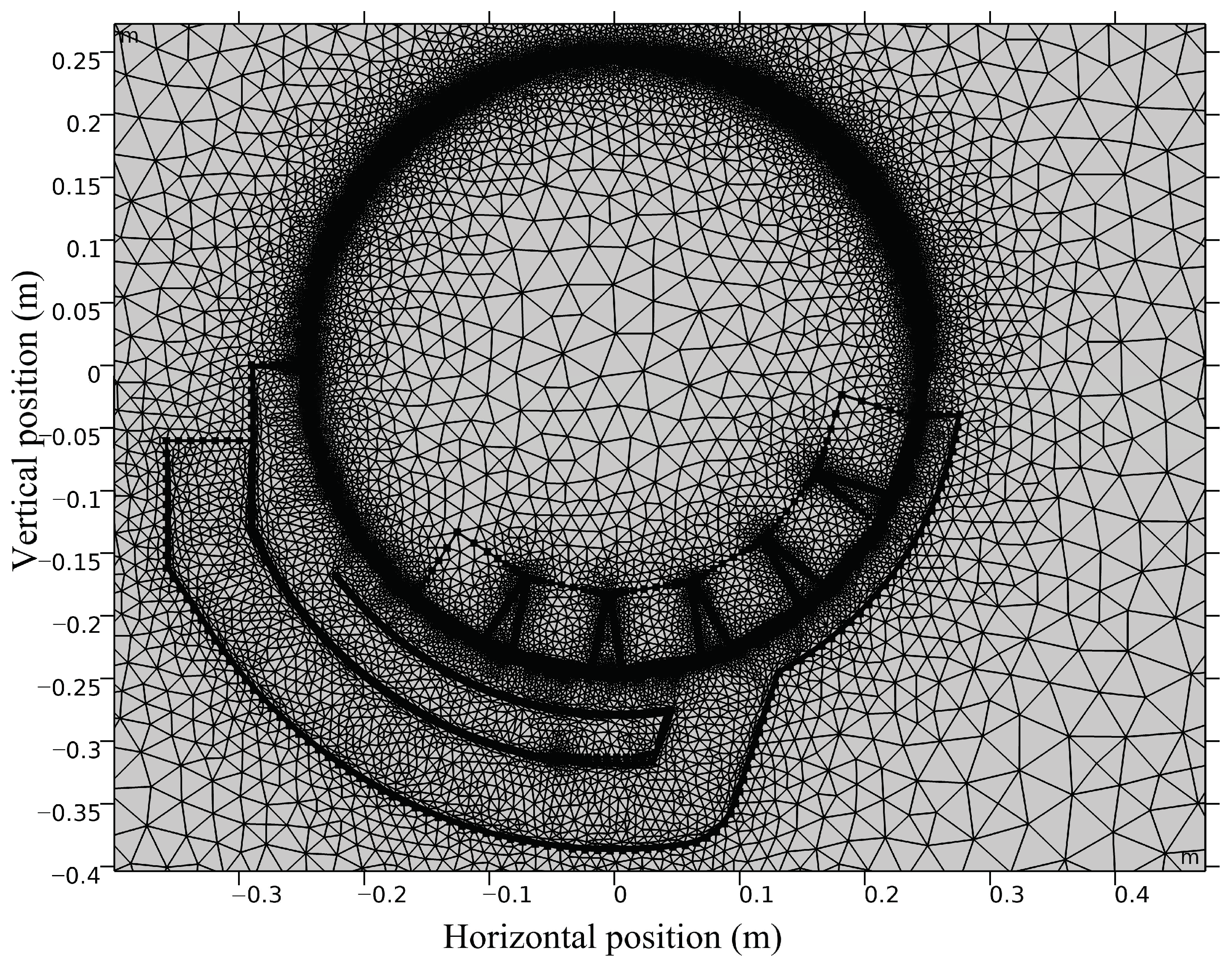
We previously found that there was an observable difference between laboratory-scale test results and the industrial production index for separating cyanidation tailings using LIMS; i.e., comparing to the concentrate produced from industrial production LIMS at 0.40 T magnetic induction, the laboratory-scale LIMS achieved a higher magnetite recovery at a lower magnetic induction of 0.20 T. Based on the properties of slimed cyanidation tailings, we have sufficient reason to believe that the ultra-fine magnetite capture in LIMS is very sensitive to the hydrodynamic parameters, which closely relates to the operating conditions, such as solid weight of pulp, pulp flow, and separation gap in the LIMS separator. But these have been little investigated in the literature. One of the main reasons is that the solid weight of pulp and feed flow factors cannot be investigated at cyclic and bench-scale LIMS separation. Thus, in this study, continuous and pilot-scale LIMS tests were performed to separate ultra-fine magnetite from cyanidation tailings, which were produced from a super-large gold mining company in the Heqing area of Yunnan Province, China. And an attempt was made to regulate solid weight, feed flow, and separation gap to enhance ultra-fine magnetite recovery. In addition, the effects of key hydrodynamic parameters on the capture of ultra-fine magnetite were theoretically analyzed via flow dynamics simulation. This work may provide theoretical guidance for the scientific regulation of and improvement in ultra-fine magnetite recovery in practice.

2. Experimental Method

2.1. Properties Analysis of Cyanidation Tailings

The cyanidation tailings used for properties analysis were sampled from the discharging port of cyanidation tailings in industrial production process of Beiya Mining Co., Ltd., Heqing, China. All the cyanidation tailings samples were naturally air-dried and then gently broken up into powders using a roller. The chemical compositions of the sample were analyzed via element dissolution and Atomic Absorption Spectroscopy (AAS), with a deviation of less than 0.10%. The iron phase analysis was performed in terms of dissolution properties and rates of different iron phases in various chemical solutions, and AAS, with a deviation of less than 0.50%. The compositions and iron phase analysis results are illustrated in Table 1 and Table 2, respectively. Table 1 shows that the cyanidation tailings contain 15.68% iron, which is mainly distributed in magnetite and limonite particles. As shown in Table 2, the iron grades of magnetite and limonite in the cyanidation tailings are 3.08% and 12.42%, respectively, with their iron distributions relative to total iron reaching 19.66% and 79.19%, respectively.
The sample particle sizes were analyzed by wet sieving for +45 µm fractions and elutriation for −45 μm fractions. Elutriation was performed as follows. The solid density of the sample was determined using a volumetric flask. Equation (1) was used to calculate the settling times (t) required for different particle sizes [14]. A slurry (3% solid weight; 50 g sample + 2000 mL water) was fully suspended by manual stirring. After the settling time had elapsed, the targeted-suspended size fractions were siphoned off along with water. This procedure was repeated until the siphoned pulp contained no obvious solid particles. This method was used to classify each size fraction from fine to coarse by shortening the time. The fractions were filtered, dried, and weighed. The iron grades of each size fraction were determined by chemical analysis, as shown in Table 3. It shows that the weight and iron distribution of −25 μm fraction were 64.20% and 54.53%, respectively, indicating that the cyanidation tailings were seriously muddied, with most iron minerals occurring as ultra-fine particles. This is attributed to the total-slime cyanide leaching operation for gold and silver extraction in the upstream process.
t s = h 545 d 2 ρ s 1000
where h is the sedimentation distance (m), d is the grain diameter (m), and ρs is the solid density (kg/m3).

2.2. Liberation and Mineragraphy Characteristics of Magnetite in Cyanidation Tailings

2.2.1. Mineral Liberation Analysis (MLA)

The mineral compositions, liberation characteristics, and disseminated grain size of minerals in cyanidation tailings were determined by MLA system, which consisted of a 650-type mineral liberation analyzer (FEI Company, Hillsboro, OR, USA), an FEI Quanta 650 scanning electron microscope (SEM), an energy-dispersive X-ray spectrometer, and a DATAVIEW software for image optimization. During the MLA analysis, approximately 60,000–80,000 particles in the samples were automatically observed and counted to reflect the liberation characteristics of the target minerals, and the mineral compositions were determined by comparing them with the Minerals Database in the MLA system.
The image formation of liberation characteristics for minerals in the cyanidation tailings is exhibited in Figure 1. It can be seen that the gangue minerals in the cyanidation tailings are mainly composed of quartz, dolomite, plagioclase, calcite, and a small amount of feldspar and kaolinite. Moreover, there are complex mineral liberation characteristics of minerals in the cyanidation tailings, which may result in the difficulty in iron mineral enrichment.
Table 4 shows the quantified liberation of main iron minerals in the cyanidation tailings. It should be noted that the liberation degree is defined as the volume ratio of targeted iron mineral grains in a particle, while the liberation proportions describe the proportion of targeted iron mineral particles with a liberation degree to the totally observed particles that contain magnetite or limonite. From Table 4, it can be derived that the cyanidation tailings had a proportion of fully liberated particles, only reaching 16.52% for magnetite and 65.90% for limonite, respectively. The proportions for above half liberation degree were lower than 50% for magnetite. This demonstrates that abundant magnetite occurred as ultra-fine intergrowth in the cyanidation tailings.
Figure 2 shows the disseminated grain size analysis of magnetite and limonite in the cyanidation tailings, which was obtained by counting data from the MLA system. The cumulative distributions of magnetite above 6 μm, 16 μm, 25 μm, and 45 μm size ranges were 32.10%, 45.39%, 54.54%, and 91.71%, respectively, while the cumulative distributions of limonite above 6 μm, 16 μm, 25 μm, and 45 μm size ranges were 24.66%, 39.69%, 50.80%, and 90.81%, respectively. These results confirm that the magnetite and limonite minerals mainly occurred as fine and ultra-fine particles in the cyanidation tailings, which is problematic for iron recovery during magnetic separations.

2.2.2. SEM Analysis

In order to directly observe mineral paragenesis in the cyanidation tailings, SEM (SEM5000, ChinaInstru. & Quantumtech. (Hefei) Co., Ltd., Hefei, China) analysis was performed, and the backscattered and mapping SEM images are recorded in Figure 3. From Figure 3, it can be clearly seen that most incompletely liberated magnetite particles mainly associate with limonite, in forms such as a limonite coating on magnetite, and magnetite finely disperses in limonite. The rest of incompletely liberated magnetite particles are adjacently associated with quartz. This would result in negative effects on the recovery of ultra-fine magnetite particles in the LIMS process.

2.3. LIMS Separator

Wet drum LIMS separators (semi-reflux type, SLon Magnetic Separator Ltd., Ganzhou, China) with several small permanent magnetic blocks, as shown in Figure 4, were used to recover magnetite from the cyanidation tailings. Firstly, the separation gap, namely the maximum distance between the drum surface and the bulkhead, was adjusted by increasing the thickness of the gasket supporting the tank support. When the LIMS separator was being operated, the drum rotation was controlled by a frequency converter. Then, the cyanidation tailing slurry was fed into the separator at a constant flow to ensure the pulp did not overflow the separating zone. Magnetite particles were attracted from the slurry onto the drum surface and transferred to the concentrate flushing zone by the rotating drum, while weakly magnetic and non-magnetic particles exited the separating zone to become tailings.

2.4. Pilot-Scale Magnetic Separation Test

Three pilot-scale LIMS separators were connected for magnetic separation tests, as shown in Figure 5. Two Φ 500 × 600 separators, respectively, undertook roughing (magnetic induction = 0.40 T) and scavenging (magnetic induction = 0.50 T) operations, while a Φ 400 × 600 separator (magnetic induction = 0.30 T) undertook the cleaning operation.
The feed used for pilot-scale testing was directly divided from the pipe for cyanidation tailings discharge in the industrial production process. It was introduced into a 1.0 m3 agitator at 1400 rpm stirring, and its solid weight was adjusted using industrial water at a constant flow.
During the pilot-scale tests, the pulp flow and solid weight of cyanidation tailings fed in each test were firstly controlled at a stable value via a valve. The products, including feed, concentrates, and tailings from each separator, were sampled every 15 min, and each test was sampled 6 times. The samples were dried, blended, and split for iron and magnetite grade determinations, which were performed via the chemical analysis method described in Section 2.1, respectively. Then, the weight percent, Fe, and magnetite recoveries were calculated according to Equations (2)–(6).
γ 1 = γ 2 + γ 3 = 100 %
γ 1 × β 1 = γ 2 × β 2 + γ 3 × β 3
α 1 = α 2 + α 3 = 100 %
α 2 = γ 2 × β 2 γ 1 × β 1 × 100 %
α 3 = γ 3 × β 3 γ 1 × β 1 × 100 %
where γ1, γ2, and γ3 are the weight percents of feed, concentrate, and tailings, respectively; β1, β2, and β3 are the Fe or magnetite grades of feed, concentrate, and tailings, respectively; α1, α2, and α3 are the Fe or magnetite recoveries of feed, concentrate, and tailings, respectively.

2.5. Simulation Model and Computational Methods

The COMSOL Multiphysics simulation software, based on the finite element method, was used to investigate the separation behavior of ultra-fine magnetite particles in the semi-countercurrent LIMS separator. Two-dimensional physical model was established, as shown in Figure 6, with a free triangle grid at maximum and minimum grid sizes of 51.300 mm and 0.173 mm, respectively. In addition, the values of the maximum cell growth rate, curvature factor, and narrow-region resolution were, respectively, set at 1.25, 0.25, and 1.00 [18].
The dynamic fluid behavior of pulp in the separation zone is calculated using the continuity equation for fluid flow [19,20], as described by Equations (7)–(12).
ρ ·   u   = 0
ρ u · u = · p l + K + F + ρ g
K = μ + μ T u + u T
ρ u · k = · μ + μ T σ k k + P k ρ ε
ρ u · ε = · μ + μ T σ ε ε + C 1 ε ρ S ε C 2 ε ρ ε 2 k + v ε
μ T = ρ C μ k 2 ε
where u is the velocity component (m/s); = x i , y j is the Hamiltonian operator; t is time (s); p is the fluid pressure (Pa); ρ is the fluid density (kg/m3); the bulk volume of the liquid F = ρ g , g is the gravitational acceleration (m/s2); K is the viscosity stress tensor of the Newtonian fluid (N/m2); μ is the fluid viscosity coefficient (Pa × s); k and ε are the turbulent kinetic energy and the turbulent dissipation rate, respectively; ε = ep ; P k = μ T u : u + u T is the turbulent kinetic energy generated by the laminar velocity gradient (J); μT is the turbulent velocity (m/s); σk, σε are the turbulent Prandtl numbers for the equations k and the ε equation; Cμ, C and C values are 0.09, 1.44, and 1.92, respectively [21].
During the magnetite capture simulation, the background magnetic induction was set at 0.4 T (Figure 7a) in the light of the LIMS separator that was used in the industrial production process. After setting pulp flow and separation gap, as shown in Figure 7b, the particles and water are put at the feed port of the model, and they freely move towards the tailings discharging port. When they pass through the separation zone, the captured particles adhere to the drum, while the uncaptured particles are frozen and counted at the tailings port. These are counted as a reference for evaluating the separation effect. Furthermore, due to the ultra-fine property of the mineral particles, the inertial and diffusion effects become insignificant. Thus, a primary focus on the examination of magnetic and drag forces is required [22,23].

3. Results and Discussion

3.1. Magnetite Recovery from Cyanidation Tailings Using LIMS

3.1.1. Effect of Feed Flow

The feed flow directly decides the feed velocity while the separation gap remains constant, which is a key factor that affects the capture of strongly magnetic minerals when a wet drum magnetic separator is used. The effect of feed flow on the LIMS roughing performance is shown in Figure 8. The increase in the feed flow led to an improvement in the concentrate grade. However, the iron recovery of the concentrate slowly decreased with an increase in feed flow from 4.0 m3/h to 6.0 m3/h, and this decrease sharply enhanced when the feed flow reached to 8.0 m3/h. This recovery decrease occurred because of more ultra-fine magnetite particles and magnetite intergrowth particles were washed out when they were subjected to stronger hydrodynamic competing force and relatively weaker magnetic capture forces at higher feed flow. In addition, the strong drag force of slurry acts on the drum surface when the flow rate is high, resulting in the unstable adsorption of magnetite. Although the 4.0 m3/h feed flow achieved the highest iron recovery, a 6.0 m3/h feed flow is more suitable for the whole LIMS process due to its superior processing capacity for cyanidation tailings. In addition, it has relatively higher selectivity compared with the 4.0 m3/h feed flow. Such roughing tailings can be further scavenged to recover partial magnetite at a relatively high magnetic induction. For the feed at 20.43% iron grade, a roughing magnetite concentrate assaying 57.63% Fe at 32.94% iron recovery was obtained.

3.1.2. Effect of Separation Gap

One essential feature in LIMS technology is the separation gap in the separating zone. Therefore, in this study, the effect of the separation gap on the LIMS roughing performance was investigated, and the results are shown in Figure 9. It should be noted that the feed flow changes accordingly when the separation gap is changed, in order to ensure the feed velocity remains constant. Figure 9 shows that the separation gap has a very significant influence on the separation performance of LIMS roughing. The iron recovery of the concentrate slowly decreased with an increase in the separation gap from 15 mm to 30 mm, and this decrease sharply enhanced when the separation gap reached greater than 30 mm. And the concentrate grade increased with an increase in the separation gap. These are attributed to the capture probability of the particles containing magnetics decreasing with the increasing of distance between ore particles and the drum surface. Under conditions of a 25 mm separation gap and the iron grade of the feed at 17.30%, a roughing concentrate assaying 59.24% Fe at 18.61% iron recovery was obtained. This illustrated that the processing capacity of the LIMS separator is significantly reduced when the separation gap is less than 25 mm, which is infeasible for industrial separation.

3.1.3. Effect of Drum Rotating Speed

The LIMS roughing separation performance at different drum rotating speeds is shown in Figure 10. When the drum rotating rate was increased from 15 to 45 rpm, there was little variation in the iron grade and recovery of the roughing concentrate. When the rotating rate was increased to 50 rpm, although the iron recovery was increased to 32.33%, the grade was decreased below 50%. This is attributed to the fact that the running frequency of drum capturing is increased at a high rotating speed, leading to a decrease in the separation accuracy. Although the iron grade of the concentrate could be improved via cleaning operation at a high drum rotating speed, 35 rpm is proposed as a suitable value for industrial separation. This is because running the drum at full load would result in instability and insecurity.

3.1.4. Effect of Solid Weight

Solid weight closely relates to the dispersity of particles in the pulp when a continuous LIMS separator at pilot scale is used. Table 5 shows the indices of the concentrate produced at various solid weights of feed pulp. From Table 5, the iron grade of the concentrate decreased, and the iron recovery of the concentrate increased with an increase in solid weight. This is attributed to the fact that entrainment is obviously generated at a high solid weight, while the separation accuracy increases with decreasing solid weight. Similar results can be observed in laboratory-scale LIMS tests, which are performed at very low solid weight (4–5%). These indicate that the drum capture for ultra-fine magnetite from such cyanidation tailings is very sensitive to solid weight and illustrate the requirement for performing pilot-scale tests.

3.1.5. Whole Process Test

After optimizing the operation conditions of cleaning and scavenging, like the procedure used in roughing tests, a whole LIMS process test was performed under optimized operating conditions, as illustrated in Figure 11, and the results are summarized in Table 6. The results showed that the magnetic separation test process produced a high-grade magnetite concentrate assaying 63.31% Fe with 4.21% iron productivity.
To analyze the impact of flow field optimization on magnetic separation, the size fraction distribution of concentrates from both the whole process test and industrial production was analyzed. The results are shown in Table 7. It shows that the iron recovery in the fraction decreased as the size fractions increased when the particle size was larger than 16 μm. This may be attributed to the comparatively low liberation rate of magnetite in the coarse fractions, while the opposite tendency of iron recovery is observed when the particle size is less than 25 μm, suggesting that the magnetite capture significantly decreases as the particle size decreases in the ultra-fine size fraction. In addition, the iron recoveries in the −16~+6 and −6 fractions from the test concentrate reached 18.51% and 9.10%, respectively. These represent increases of 3.66% and 4.42%, respectively, compared to the concentrate produced from industrial production.
Figure 12 shows the existence characteristics of mineral particles in the LIMS process tailings. From Figure 12, the magnetite particles were mainly embedded in limonite particles and completely liberated particles with ultra-fine size. And the ultra-fine magnetite particles lost in the industrial production tailings were much greater than those in the test tailings. These results clearly confirm that the recovery of ultra-fine magnetite can be effectively improved via the optimization of flow field parameters.

3.2. Flow Dynamics Simulation

The flow dynamics simulation was used to visually analyze the capture mechanism of ultra-fine magnetite particles, which is challenging to investigate due to the invisible structure of a separation chamber in the LIMS separator and the occurrence of potentially multiple factors interacting in pilot-scale separation. In this section, the effects of particle sizes, flow velocity, and separation gap on the capture performance of magnetite particles were investigated in terms of the pilot test conditions, converting the flow rate to flow velocity.

3.2.1. Simulation of Particle Separation

The simulation reliability was preferentially measured at optimized pilot-scale test conditions of 25 mm separation gap, 0.4 T magnetic induction, and 0.0637 m/s flow velocity obtained from pilot-scale separation tests. In this simulation measurement, 52 magnetite particles of 45 μm, 195 magnetite particles of 25 μm, 104 magnetite particles of 16 μm, and 310 magnetite particles of 6 μm were together fed into the separator within 10 s, and the results are shown in Figure 13 (the red particles in the figure represent magnetite particles in the simulation). It shows 19 magnetite particles were counted at the tailings port, accounting for 2.87% of magnetite particle loss. The measurement results indicate that the reliability of the simulation is adequate.

3.2.2. Effect of Particle Size on Magnetic Capture

Magnetite particles with different sizes were simulated using optimized pilot-scale test conditions to analyze their separation route in a LIMS separator. Figure 14 shows the capture proportions of magnetite particles with different sizes in the simulation. From Figure 14, the capture proportions of 45 μm, 25 μm, and 16 μm magnetite particles are all 100%, while it is only 41.82% for 6 μm magnetite particles. This confirms that the magnetite particle is very easy to lose in the LIMS process when its size is below 6 μm. In addition, the magnetite capture proportions of the simulation are somewhat higher than the recovery of magnetite in pilot-scale separation. This may be caused by the underflow of flushing water in the pilot-scale LIMS separator.
Figure 15 shows the magnetic force and drag force acting on particles of various sizes within the simulations, and the resultant forces affecting on the particles are summarized in Table 8. In Figure 15a, the magnetic force acting on the magnetite particle decreases as the particle size decreases from 45 μm to 16 μm. Such a decrease was significantly enhanced when the particle size reached 6 μm, which featured a minimum magnetic force of only 9.87 × 10⁻¹⁰ N. Figure 15b shows that the drag force acting on particles of different sizes follows a similar trend to the magnetic force. The maximum drag force acting on the 45 μm particles is 6.50 × 10⁻⁷ N; when the particle size decreases to 6 μm, the drag force is only 7.26 × 10⁻¹⁰ N. According to Table 8, the resultant force decreases as the particle size decreases. When the particle size is only 6 μm, the resultant force is only 2.61 × 10⁻¹⁰ N.
It is noted that when the magnetic field strength remains consistent, both the magnetic force and drag force acting on the particles decrease as the particle size decreases. For a LIMS separator in actual production, it commonly equips a permanent magnet system. Therefore, controlling the LIMS at low feed flow is a reasonable way to enhance ultra-fine magnetite particle recovery in industrial production.

3.2.3. Effect of Flow Velocity on Magnetic Capture

The flow field operating conditions improved magnetite recovery in LIMS, which can be summarized as the effect of flow velocity. Thus, the effect of flow velocity on the 6 μm magnetite capture and the force analysis of particles were simulated, and the results are shown in Figure 16 and Figure 17.
It can be seen from Figure 16 that the capture proportion of 6 μm magnetite particles significantly decreased with an increase in flow velocity from 0.0310 m/s to 0.0637 m/s, and this decrease weakened when the flow velocity reached higher than 0.0637 m/s. From Figure 17, the drag force acting on the 6 μm magnetite particle is 1.04 × 10⁻¹⁰ N, 1.54 × 10⁻¹⁰ N, 3.0 × 10⁻¹⁰ N, 6.82 × 10⁻¹⁰ N, and 1.07 × 10⁻⁹ N when the flow velocity is 0.0310 m/s, 0.0474 m/s, 0.0376 m/s, 0.0801 m/s, and 0.0964 m/s, respectively. Namely, the drag force of the particles significantly increases with a feed flow increase.
It is noted that the feed flow velocity significantly affects the magnetic capture for ultra-fine magnetite particles, especially for magnetite particles smaller than 6 μm. While these factors determine the pulp flow velocity and the hydrodynamic competing force acting on the particles during the practical separation, these are the key parameters when considering the ultra-fine magnetite recovery. Therefore, these results suggest that the capacity of the LIMS separator selected for industrial production requires a suitable expansion for treating such specific and ultra-fine cyanidation tailings.

4. Conclusions

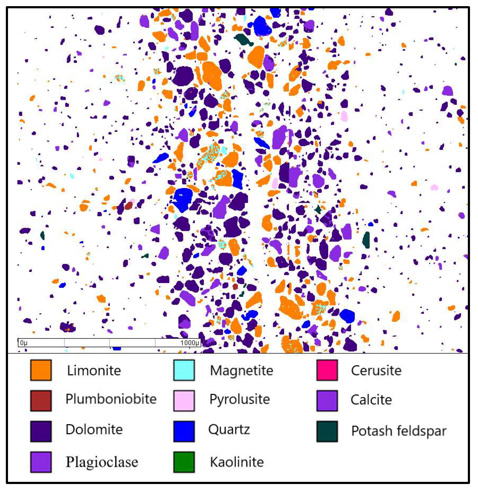
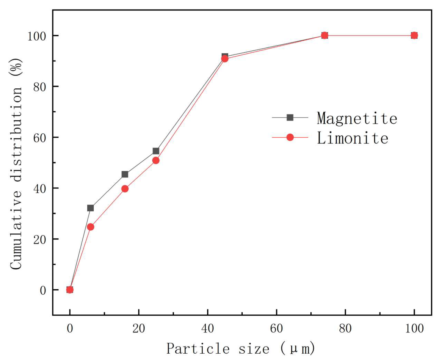
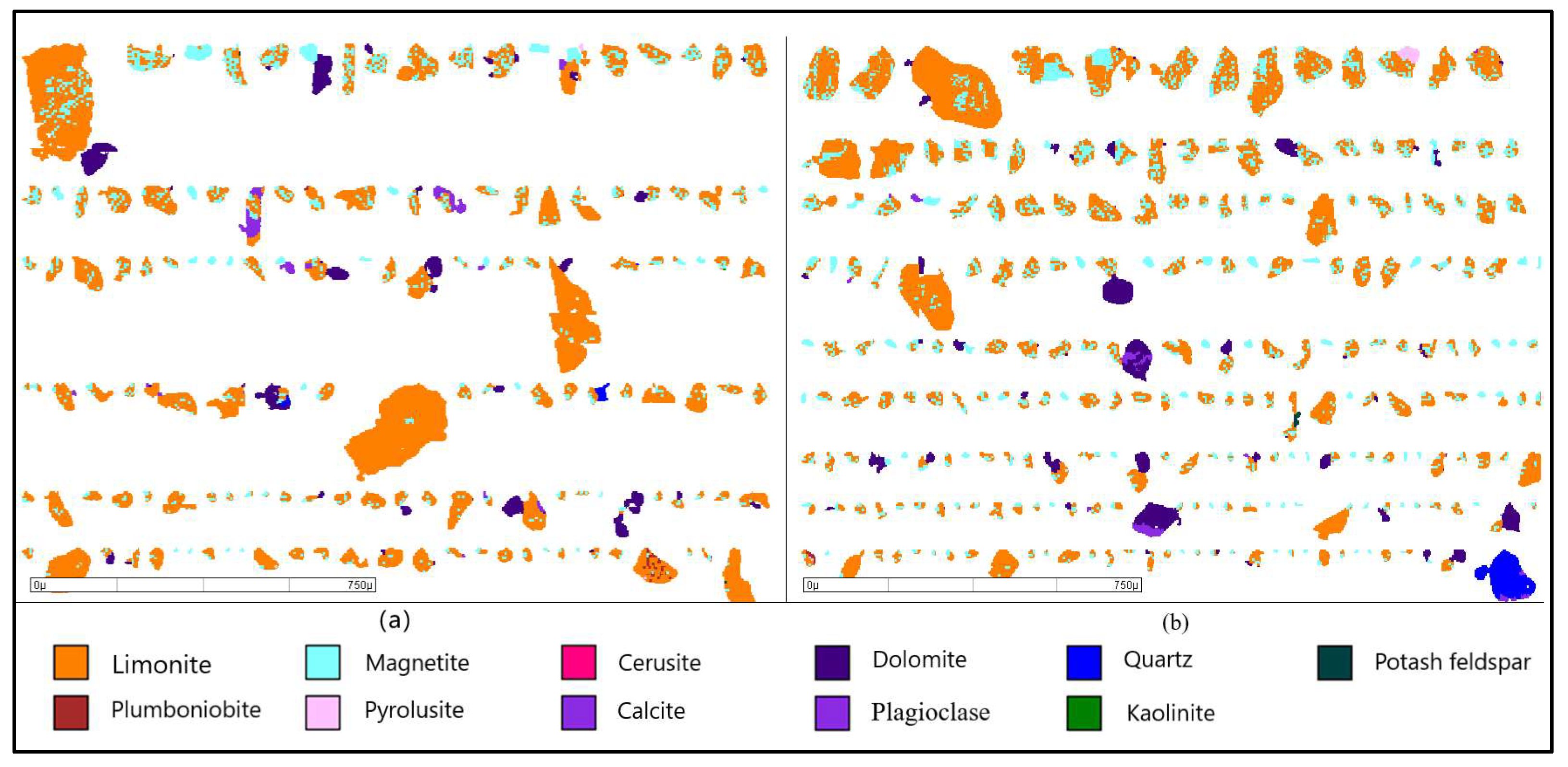
The cyanidation tailings contained 15.68% Fe, with iron mainly distributed in the forms of magnetite and limonite. The iron grades from magnetite and limonite in the cyanidation tailings were 3.08% and 12.42%, respectively, reaching 19.66% and 79.19% distributions to the total iron, respectively. The cyanidation tailings had a proportion of full liberation particles reaching 16.52% for magnetite and 65.90% for limonite, respectively. The distributions of fine (+6–16 µm) and ultra-fine (−6 µm) magnetite particles in the cyanidation tailings reached 13.29% and 32.10%. Complete recovery for ultra-fine magnetite and its intergrowth is a key step affecting the total iron utilization from cyanidation tailings.
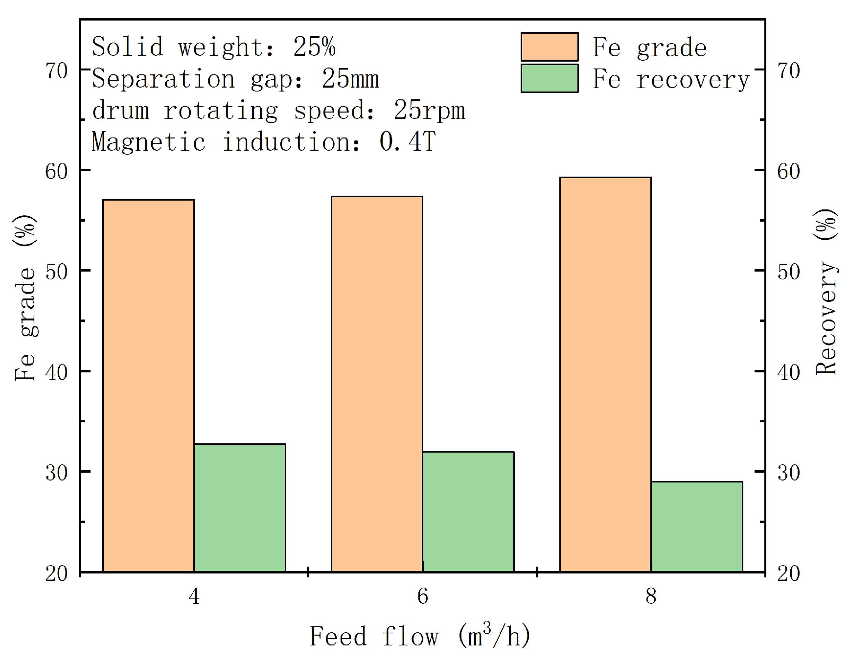
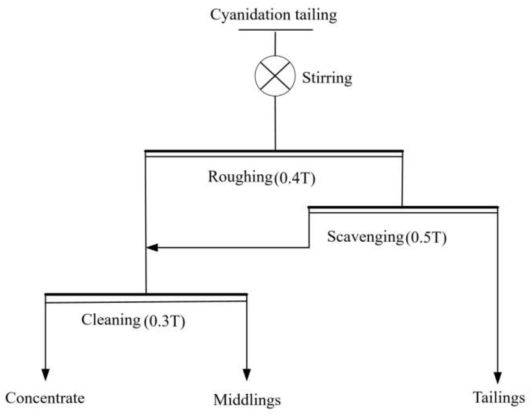
Using a LIMS roughing (0.40 T)–scavenging (0.50 T)–cleaning (0.30 T) process, a concentrate with 4.21% weight, 63.31% Fe grade, and 86.46% magnetite recovery was produced under optimum conditions. Compared to the results obtained from industrial production, the grade and magnetite recovery were increased by 0.76% and 15.22%, respectively. The recovery for ultra-fine (−6.0 µm) magnetite from the cyanidation tailings was improved via the regulation and controlling of feed flow and separation gap, namely reducing the drag force effect of particles in LIMS.
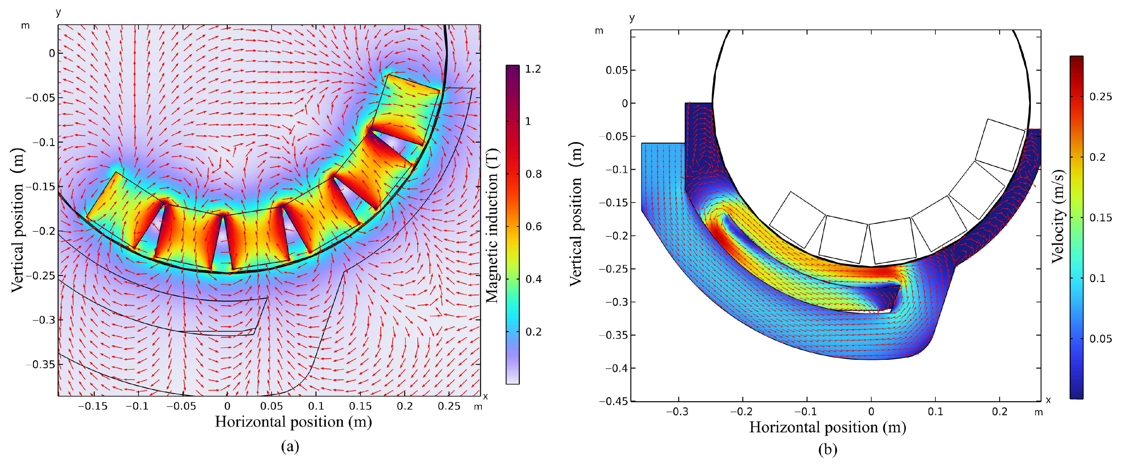
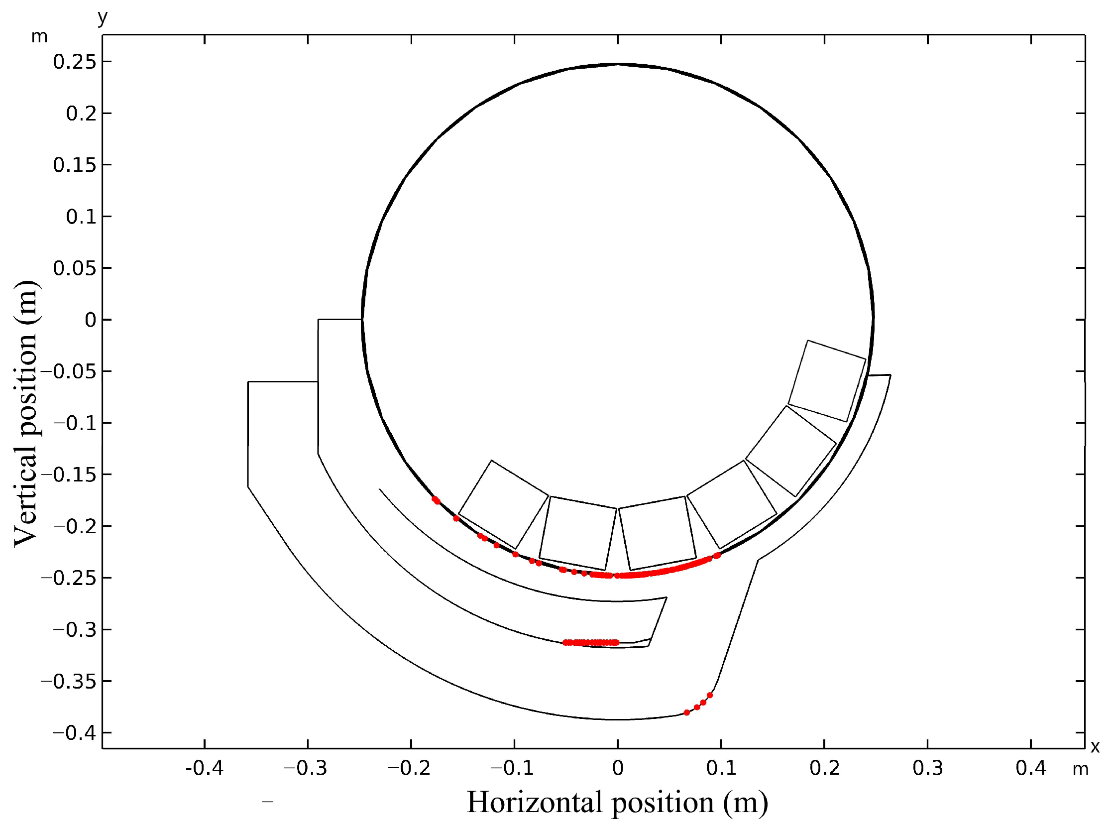
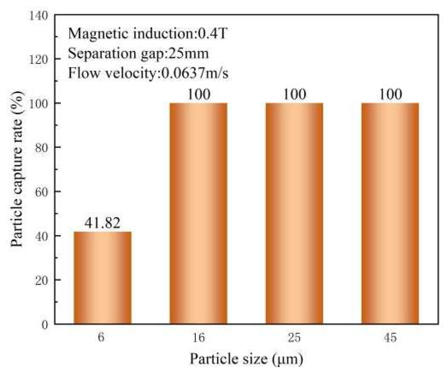
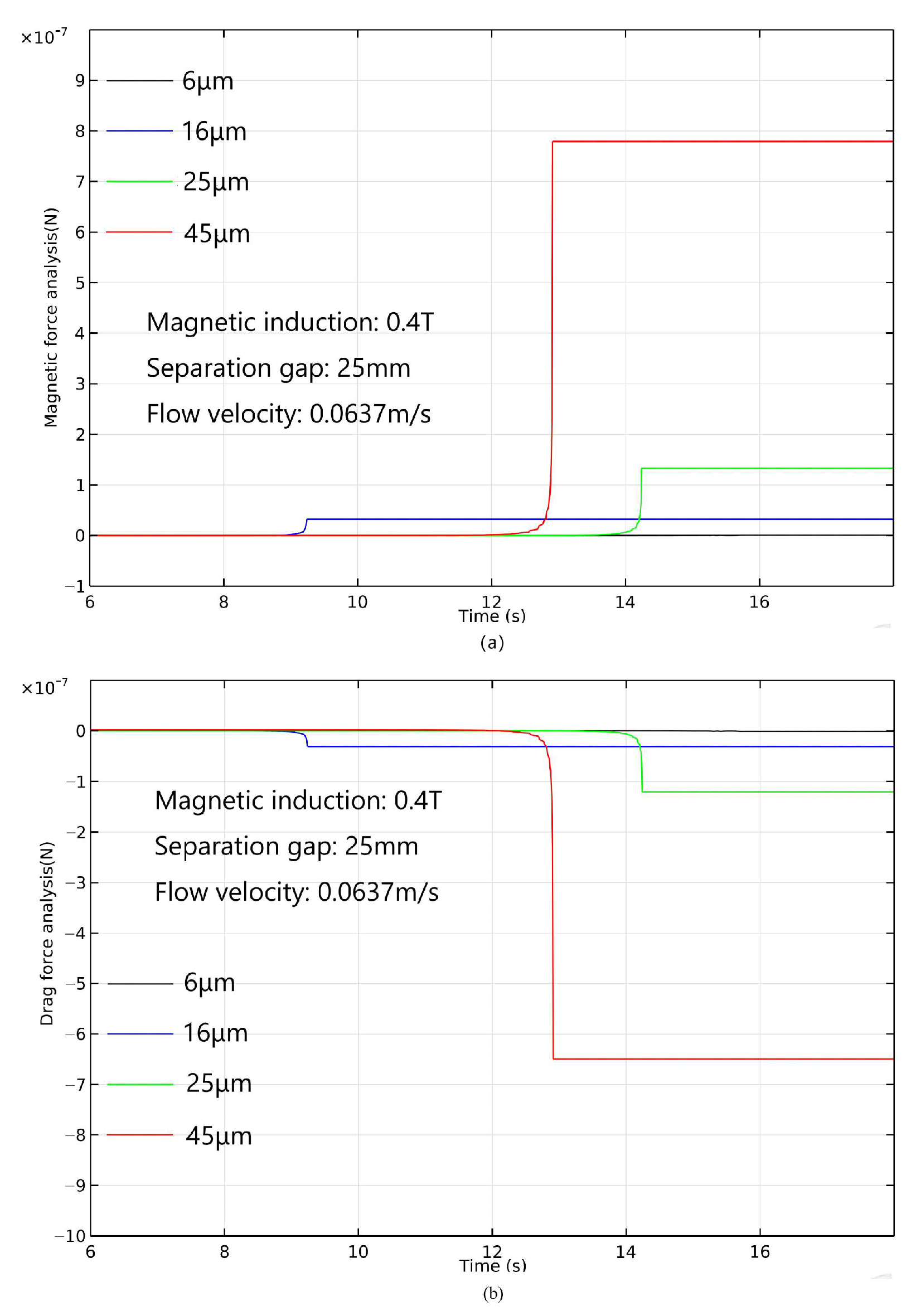
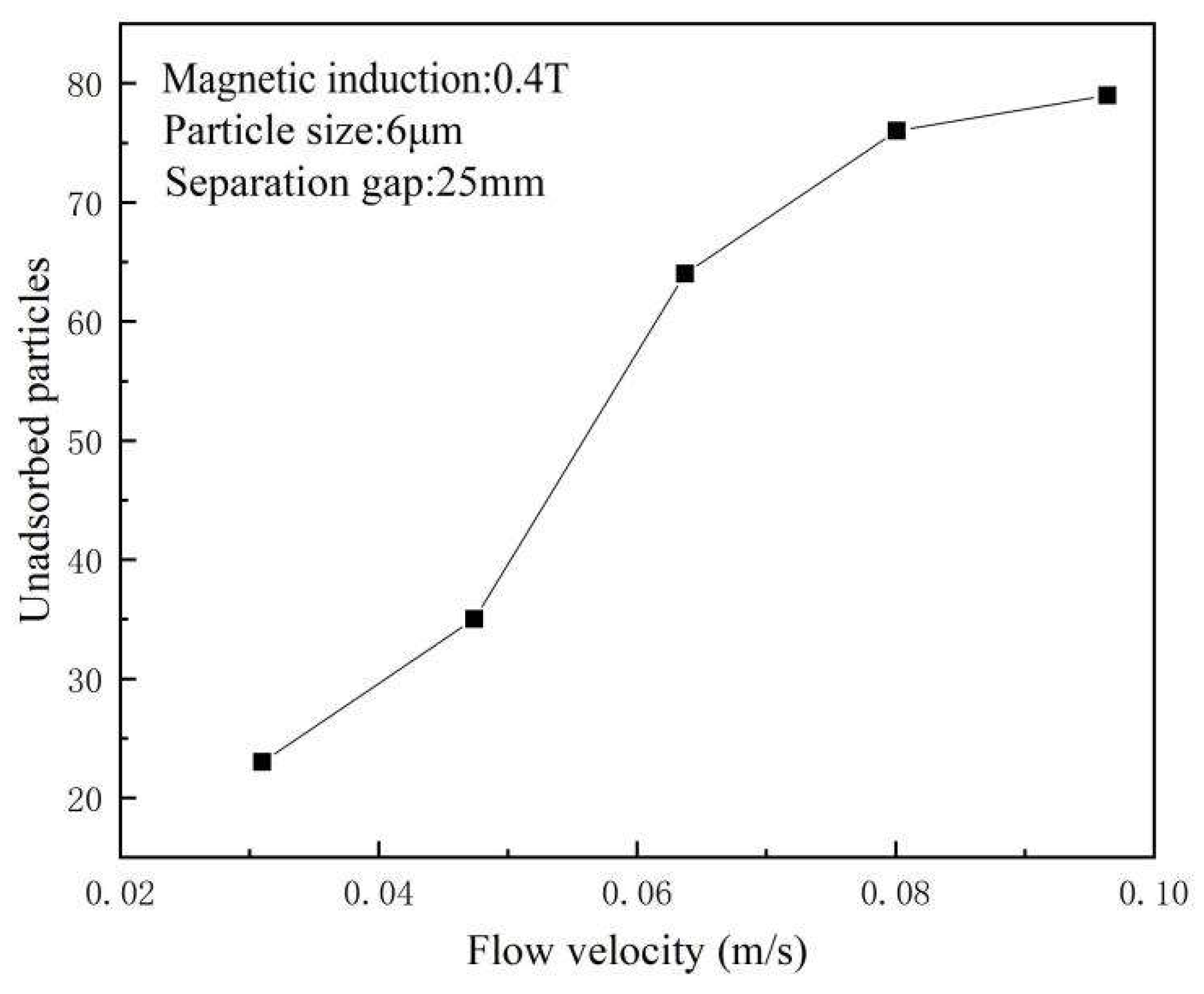
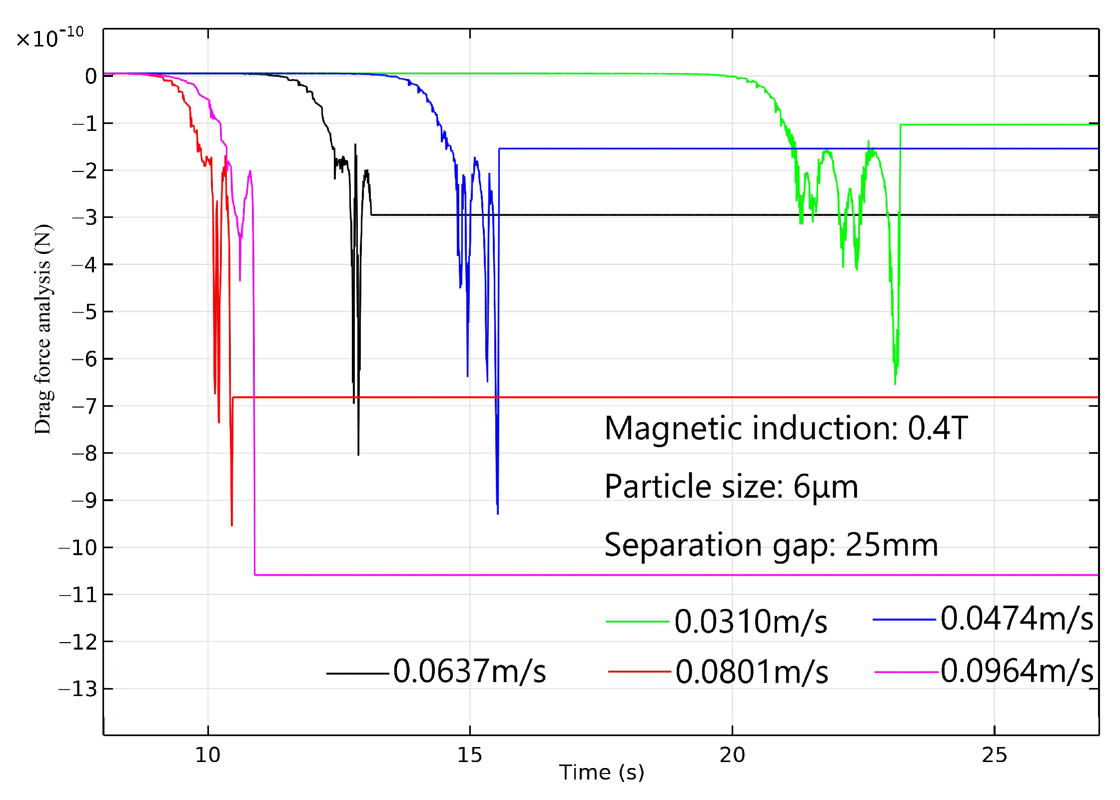
From the results of hydrodynamics simulations, the main magnetite particles lost were smaller than 16 μm. This is because of the significant difference in value between the maximum magnetic force and the drag force acting on the particle, which decreases when the particle is smaller than 16 μm. As a result, the particle cannot reach the larger magnetic position or may be disturbed by other non-magnetic minerals and lost into the tailings. The simulation outcomes suggest maintaining a flow velocity of 0.0637 m/s when the magnetic induction is set to 0.4 T. This approach ensures both processing capacity and a sufficient difference in value between magnetic and drag forces, thus optimizing the separation efficiency. This research work provides a valuable reference for the comprehensive utilization of iron values from such residues.

Author Contributions

Conceptualization: Y.J., Y.X. and L.C.; supervision: Y.X. and L.C.; methodology: Y.J., Y.X. and L.C.; investigation: Y.C., Y.J., L.C., and Y.X. data curation: Y.C. and Y.J.; visualization: Y.C.; writing—original draft preparation; writing—review and editing: Y.C. and Y.X.; funding acquisition: Y.J. and L.C. All authors have read and agreed to the published version of the manuscript.

Funding

This research project was supported by the National Natural Science Foundation of China (No. 52264027), the High-Level Talent Recruitment Program of Yunnan Province (No. CCC21321005A) and the Top-Notch Young Talents Project of Ten Thousand Program of Yunnan Province (No. YNWR-QMBJ-2019-051).

Data Availability Statement

The original data used in this research can be requested at any time by contacting the corresponding author: [email protected].

Acknowledgments

We are grateful for the technical support from the Kunming Metallurgical Research Institute.

Conflicts of Interest

Author Yaxiong Jiang was employed by the company Yunnan Gold Mining Group Co., Ltd. The remaining authors declare that the research was conducted in the absence of any commercial or financial relationships that could be construed as a potential conflict of interest.

References

  1. Ma, Y.W. Beneficiation tests on ultra low grade magnetite ore from Dabagou in Inner Mongolia. Met. Mine 2014, 6, 65–68. (In Chinese) [Google Scholar]
  2. Feng, S.C.; Qing, Z.R. Strengthening the guarantee strategy of domestic iron ore resources. China Steel Focus 2022, 18, 48–51. (In Chinese) [Google Scholar]
  3. Zheng, C.L.; Chang, Y.F.; Yuan, J.S.; Xie, M.X.; Jiang, W.; Xu, G.P.; Dong, G.Q.; Lu, D.K. Pressure filtration and cake washing for cyanide removal from all-slime cyanidation tailing. Nonferrous Met. (Extr. Metall.) 2021, 9, 75–79. (In Chinese) [Google Scholar] [CrossRef]
  4. Su, T.; Chen, T.J.; Zhang, Y.M.; Lu, M. The separation study on micro-fine disseminated and low-grade magnetite. Min. Res. Dev. 2015, 35, 38–42. (In Chinese) [Google Scholar]
  5. Li, Z.C. Study on the current situation and development trend of hematite mineral processing technology. Metall. Mater. 2019, 39, 113–114. (In Chinese) [Google Scholar]
  6. Chen, Z.Y.; Feng, Q.M.; Shi, Q. Reclaiming hematite from magnetic separation tailings of fine magnetite ore. Min. Metall. Eng. 2016, 36, 60–63. (In Chinese) [Google Scholar] [CrossRef]
  7. André, F.P.; Miceli, H.; Moura, L.C.; Neumann, R.; Tavares, L.M. Upgrading a manufactured fine aggregate for use in concrete using dry rare-earth magnetic separation. Miner. Eng. 2019, 143, 105942. [Google Scholar] [CrossRef]
  8. Ding, P. Study on recovery technology of fine magnetite from copper tailings of a large copper mine in Anhui province. World Nonferrous Metals 2019, 15, 155–157. (In Chinese) [Google Scholar] [CrossRef]
  9. Su, T.; Chen, T.J.; Zhang, Y.M.; Hu, P.W.; Feng, Y. Influence of dispersion-flocculation on micro-fine magnetite low intensity magnetic separation. Metal Mine 2016, 9, 83–87. (In Chinese) [Google Scholar] [CrossRef]
  10. Allan, G.C.; Woodcock, J.T. A review of the flotation of native gold and electrum. Miner. Eng. 2001, 14, 931–962. [Google Scholar] [CrossRef]
  11. Zhang, H.J.; Liu, J.T.; Wang, Y.T.; Cao, Y.J.; Ma, Z.L. Research on cationic reverse flotation of magnetite using a flotation column. J. China Univ. Min. Technol. 2008, 37, 67–71. (In Chinese) [Google Scholar] [CrossRef]
  12. Liao, Y.F.; Ma, Z.L.; Cao, Y.J. Improving reverse flotation of magnetite ore using pulse magnetic field. Miner. Eng. 2019, 138, 108–111. [Google Scholar] [CrossRef]
  13. Wu, J.T.; Xu, B.; Zhou, Y.J.; Dong, Z.L.; Zhong, S.G.; Jiang, T. A novel process of reverse flotation-hydrogen reduction for preparation of high-purity iron powder with superior magnetite concentrate. Sep. Purif. Technol. 2023, 307, 122784. [Google Scholar] [CrossRef]
  14. Wills, B.A.; Napier-Munn, T.J. Mineral Processing Technology; Elsevier Science & Technology Books: New York, NY, USA, 2006. [Google Scholar]
  15. Wang, F.W.; Zhang, S.T.; Zhao, Z.Q.; Gao, L.K.; Tong, X.; Dai, H.X. Investigation of the magnetic separation performance of a low-intensity magnetic separator embedded with auxiliary permanent magnets. Miner. Eng. 2022, 178, 107399. [Google Scholar] [CrossRef]
  16. Guiral-Vega, J.; Bouchard, J.; Poulin, É.; Ure, A.; Breuil, C.D.; Pérez-Barnuevo, L. A Phenomenological Model for Particle Kinetics in Drum-Type Wet Low-Intensity Magnetic Separation. IFAC-PapersOnLine 2022, 55, 25–30. [Google Scholar] [CrossRef]
  17. Guiral-Vega, J.S.; Pérez-Barnuevo, L.; Bouchard, J.; Ure, A.; Poulin, É.; Breuil, C.D. Particle-based characterization and process modeling to comprehend the behavior of iron ores in drum-type wet low-intensity magnetic separation. Miner. Eng. 2024, 206, 108509. [Google Scholar] [CrossRef]
  18. Yi, F.; Chen, L.Z.; Zeng, J.W.; Ren, X.J.; Xiong, T.; Jiang, Y.X. Rotating flow characteristics in centrifugal high gradient magnetic separation and its effect on particle capture behavior. Miner. Eng. 2022, 179, 107442. [Google Scholar] [CrossRef]
  19. Schlichting, H. Boundry Layer Theory, 8th ed.; McGrawhill: New York, NY, USA, 1977. [Google Scholar]
  20. Tabatabaian, M. CFD Module: Turbulent Flow Modeling; Mercury Learning and Information: Herndon, VA, USA, 2015. [Google Scholar]
  21. Wang, F.W.; Tang, D.D.; Gao, L.K.; Dai, H.X.; Jiang, P.; Lu, M.Y. Dynamic capture and accumulation of multiple types of magnetic particles based on fully coupled multiphysics model in multiwire matrix for high-gradient magnetic separation. Adv. Powder Technol. 2020, 31, 1040–1050. [Google Scholar] [CrossRef]
  22. Zheng, X.Y.; Wang, Y.H.; Lu, D.F. Study on capture radius and efficiency of fine weakly magnetic minerals in high gradient magnetic field. Miner. Eng. 2015, 74, 79–85. [Google Scholar] [CrossRef]
  23. Moeser, G.D.; Roach, K.A.; Green, W.H.; Alan Hatton, T.; Laibinis, P.E. High-gradient magnetic separation of coated magnetic nanoparticles. AIChE J. 2004, 50, 2835–2848. [Google Scholar] [CrossRef]
Figure 1. Liberation characteristics of minerals in cyanidation tailings based on MLA analysis.
Separations 11 00120 g001
Figure 2. Particle size distributions of magnetite and limonite in cyanidation tailings.
Separations 11 00120 g002
Figure 3. Microscopic paragenesis of minerals in cyanidation tailings. Backscattered (left) and mapping (right) SEM images.
Separations 11 00120 g003
Figure 4. Schematic diagram of the semi-countercurrent magnetic separator.
Separations 11 00120 g004
Figure 5. Equipment contacting diagram (a) and photograph (b) of industrial test 1, 3—valve; 2—stirred tank; 4, 5, 6—CTB-56/54 separators.
Separations 11 00120 g005
Figure 6. Cross-section model of the semi-countercurrent magnetic separator.
Separations 11 00120 g006
Figure 7. Schematic diagram of the magnetic field (a) and flow field (b).
Separations 11 00120 g007
Figure 8. Effect of feed flow on roughing separation.
Separations 11 00120 g008
Figure 9. Effect of separation gap on roughing separation.
Separations 11 00120 g009
Figure 10. Effect of drum rotating speed on roughing separation.
Separations 11 00120 g010
Figure 11. Process flows chart of whole LIMS process test.
Separations 11 00120 g011
Figure 12. MLA analysis of minerals in tailings from the pilot test (a) and the unoptimized production line (b).
Separations 11 00120 g012
Figure 13. Simulation reliability measurement results.
Separations 11 00120 g013
Figure 14. Simulation results of magnetite particles with different sizes.
Separations 11 00120 g014
Figure 15. Analysis of magnetic forces (a) and drag force (b) acting on the magnetite particle with different sizes.
Separations 11 00120 g015
Figure 16. Simulation results of magnetite particles capture at different flow velocities.
Separations 11 00120 g016
Figure 17. Analysis of drag force at different flow velocities.
Separations 11 00120 g017
Table 1. Chemical compositions of cyanidation tailings (* g/t).
CompositionsTFeSiO2CaOMgOMnCuPbZnSPAu *Ag *
Contents (%)15.6842.6515.442.141.270.180.240.170.130.05/13.70
Table 2. Iron phase analysis of cyanidation tailings.
Iron MineralsMagnetiteLimoniteSideriteFerro-SilicateSulfideTotal
Iron grades (%)3.0812.420.050.070.0115.68
Iron distributions (%)19.6679.190.330.460.06100.00
Table 3. Size fractions analysis for iron distributions in cyanidation tailings.
Size Fractions (μm)Weight Percent (%)Iron Grades (%)Iron Distributions (%)
+455.8128.8710.69
−45~+2529.9918.1834.77
−25~+1615.1910.4810.15
−16~+619.1010.0912.29
−629.9116.8232.10
Total100.0015.68100.00
Table 4. Liberation characteristics analysis of iron minerals in cyanidation tailings.
Iron MineralsLiberation Degrees (%)Proportions (%)Cumulative Proportions (%)
Magnetite100%16.5216.52
75% < x < 100%4.7621.28
50% < x ≤ 75%26.5147.79
25% < x ≤ 50%40.0387.82
0% ≤ x ≤ 25%12.18100.00
Limonite100%65.9065.90
75% < x < 100%17.9183.81
50% < x ≤ 75%9.9893.79
25% < x ≤ 50%4.0197.80
0% ≤ x ≤ 25%2.20100.00
Table 5. Effect of solid weight on roughing separation.
Solid Weight (%)ProductsWeight Percent (%)Iron Grade (%)Iron Recovery (%)
20Feed100.0021.10100.00
Concentrate10.3857.6328.34
Tailings89.6216.8771.66
25Feed100.0020.55100.00
Concentrate11.4457.4031.95
Tailings88.5615.7968.05
30Feed100.0020.97100.00
Concentrate11.3057.3030.89
Tailings88.7016.3469.11
Table 6. Whole LIMS process test results.
Concentrates SourceProductsWeight Percent (%)IronMagnetite
Grade (%)Recovery (%)Grade (%)Recovery (%)
Whole process testFeed100.0015.68100.003.08100.00
Concentrate4.2163.3117.0063.2586.46
Middlings0.5218.030.6012.202.06
Tailings95.2713.5682.400.3711.48
Industrial production (unoptimized)Feed100.0015.59100.003.06100.00
Concentrate3.4962.5514.0062.4671.24
Middlings0.1319.640.1614.590.62
Tailings96.6813.8485.840.8928.14
Table 7. Size fractions and iron distributions analysis of magnetic concentrate.
Concentrates SourceSize Fractions (μm)Weight Percent (%)Iron Grades (%)Iron Recovery in the Fraction (%)Other Conditions
Whole process test+459.3864.1515.11Iron grade in feed (%): 15.68
Concentrate Weight percent (%): 4.21
−45~+2542.0963.3520.59
−25~+1617.8763.1729.85
−16~+613.2663.8618.51
−617.4162.499.10
Total100.0063.31
Industrial production (unoptimized)+4510.8661.0613.80Iron grade in feed (%): 15.59 Concentrate Weight percent (%): 3.49
−45~+2546.8362.4718.72
−25~+1618.8262.8825.94
−16~+613.0562.8214.85
−610.4463.534.68
Total100.0062.55
Table 8. Resultant forces on different size particle (conditions: magnetic induction: 0.4 T; separation gap: 25 mm).
Particle size (μm)6162545
Resultant force (N)2.61 × 10−101.34 × 10−91.24 × 10−81.30 × 10⁻⁷
Disclaimer/Publisher’s Note: The statements, opinions and data contained in all publications are solely those of the individual author(s) and contributor(s) and not of MDPI and/or the editor(s). MDPI and/or the editor(s) disclaim responsibility for any injury to people or property resulting from any ideas, methods, instructions or products referred to in the content.

