Abstract
The exploitation and transportation of deep-sea and remote oil and gas fields have risen to become important components of national energy strategies. The gas–liquid separation and gas blocking caused by the large density difference between the gas and liquid phases are the primary influencing factors for the safe and reliable operation of gas–liquid mixed transportation pump systems. This paper takes the independently designed single-stage helical axial-flow mixed transportation pump compression unit as the research object. Through numerical simulation, the internal flow of the mixed transportation pump is numerically calculated to study the aggregation and conglomeration of small gas clusters in the flow passage hub caused by gas–liquid phase separation, influenced by the shear flow of phase separation, forming axial vortices at the outlet where gas clusters gather in the flow passage. The work performed by the impeller on the gas clusters is insufficient to overcome the adverse pressure gradient formed at the outlet of the flow passage due to the gathering of the liquid phase in adjacent flow passages, resulting in the phenomenon of gas blocking, with vortex gas clusters lingering near the hub wall of the flow passage.
1. Introduction
Due to the significant advantages of multiphase mixed transportation systems in oil and gas extraction and transportation [1,2,3,4], an increasing number of scholars are focusing on the development of multiphase mixed-flow pumps. The helico-axial multiphase pump [5], invented and patented by the French Petroleum Institute, is an important research achievement of the Poseidon series. The first-generation Poseidon pump was developed based on electrical submersible pumps, and the second-generation Poseidon pump made significant improvements in the flow channel, adopting helico-axial impellers and optimizing the guide vanes to effectively delay or prevent the phase separation of gas–liquid two phases. This pump type consists of impellers and guide vanes to form a compression unit, whose basic principle is to rotate the impeller to allow the mixed medium to pass through and gain energy. Multiphase mixed transportation systems with helico-axial gas–liquid mixed-flow pumps as the core are gradually entering the industrial application stage.
In a centrifugal multiphase pump, due to the multiphase nature of the flowing medium and the effects of inertia, centrifugal forces, and Coriolis forces, the movement state of bubbles is unstable. Large bubbles may collapse into smaller ones, and small bubbles can aggregate into larger ones through mutual collisions. The fragmentation and aggregation play a crucial role in phase separation processes.
The multiphase flow motion inside a multiphase mixed-flow pump is intricate and complex. Under different operating conditions, it is challenging to accurately determine the pump’s performance characteristics through analytical methods alone. Therefore, experimental research on multiphase pumps is crucial. Current experimental research on multiphase pumps mainly focuses on three aspects: (1) performance testing of existing pump types under gas–liquid two-phase conveying conditions, (2) experimental research on the trajectory of gas bubbles inside the pump [6,7,8,9,10], and (3) indoor and field tests of new mixed-flow pumps [11]. Due to various issues such as experimental conditions and measurement techniques, it is currently not possible to obtain detailed and precise information about the flow of multiphase fluids inside the pump through experiments alone. However, the regular characteristics of pump transportation under different operating conditions can be generally obtained. By utilizing these characteristics, the strengths and weaknesses of pump designs can be assessed, providing guidance for further optimization of pump designs [12,13,14].
Nowadays, numerical computation is an important means for studying gas–liquid mixed transportation pumps. Numerical models can accurately predict the external characteristics of mixed transportation pumps, greatly shortening the research and development cycle of such pumps. Ming Liu et al. [15] estimated the effects of interfacial forces, including the drag force, lift force, virtual mass force, wall lubrication force, and turbulent dispersion force. They revealed the relationship between the velocity difference of gas–liquid two-phase flow and interfacial forces, as well as the relationship between interfacial forces and the gas volume fraction, and analyzed the distribution characteristics of interfacial forces from the inlet of the impeller to the outlet of the diffuser. Zhiyi Yu et al. [16,17] also considered four types of interfacial forces, namely, the drag force, lift force, virtual mass force, and turbulent dispersion force. Jinya Zhang et al. [18] conducted visual experiments to study the flow patterns of gas–liquid two-phase flow and the flow characteristics of the impeller in the inlet section of a three-stage rotary dynamic multiphase pump under different operating conditions. Kiyoshi Minemura et al. [19,20,21,22] studied the bubble motion inside the impeller of a centrifugal pump based on a theoretical research approach, analyzing the motion law of bubbles and elucidating that the controlling factors of bubble motion are the resistance of surrounding water and the pressure gradient force. They tracked the motion trajectory of bubbles in the flow channel. The performance of centrifugal pumps under gas–water two-phase flow conditions was predicted, and a one-dimensional two-fluid model consistent with fluid viscosity and compressibility of gas–air two-phase flow during the transition process from a rotating impeller to a fixed volute was established by considering the energy change. Various constitutive equations were applied to numerically solve the two-fluid model of radial flow pumps. M. van Sint Annaland et al. [23] used a three-dimensional volume method to numerically simulate bubble behavior, obtaining the trajectory of bubbles in a rotating flow field and the phase separation of gas–liquid two phases, providing guidance for analyzing the motion characteristics of bubbles in gas–liquid two-phase flow. Yu Zhiyi [24,25] and others conducted numerical simulations on the gas–liquid two-phase flow inside a mixed-flow pump. They employed the Eulerian two-fluid model with a SIMPLEC algorithm to obtain parameters such as velocity, pressure distribution, and gas–liquid distribution in the flow field. This analysis helped to identify the causes of gas accumulation inside the pump. The authors found that when there is a small radial size difference, it effectively changes the phenomenon of gas-phase accumulation. The reliability of the numerical simulation results was verified through experiments. Pang Chunbo and Yuan Shouqi [26] analyzed the geometric and dynamic characteristics of bubbles in cross-flow, including their shape, trajectory, the forces acting on them, and detachment frequency. They established a linear relationship between bubble velocity and the equivalent diameter, combining the Weber number with the bubble aspect ratio. Tsinghua University provided new data through numerical analysis of inter-phase forces between gas and liquid in multiphase pumps [27]. In a certain time and spatial scale, the formation, aggregation, and breakup of bubbles in two-phase flow led to non-periodic fluctuations in the void fraction within the cross-section [28]. Considering factors such as the pressure gradient force, drag force, and inertia force during bubble motion can more accurately simulate bubble behavior, which better corresponds to actual conditions. Therefore, Huang Si [29] proposed a three-dimensional numerical analysis method based on the bubble flow assumption. This method uses a surface iteration approach to solve the liquid-phase flow equations, while calculating the gas phase based on the known liquid-phase flow field. Zhang Kaihui studied multi-stage centrifugal pumps and established a mathematical model to compare the internal flow characteristics, pressure pulsation, and performance parameters of single-stage and multi-stage pump impellers. It was found that the performance of multi-stage pumps is influenced by interactions between stages, with severe gas accumulation and vortex generation occurring in the flow channels, and the maximum vorticity occurred at the interface between the gas and liquid phases [30]. Wang Chungang [31] studied the flow characteristics inside mixed-flow pumps using CaCO3 and water as media. Numerical simulations provided insights into the flow characteristics of solid particles in the flow field and the wear law of over-current components during solid–liquid mixed transport. Yang Hong [32] and others conducted an analysis of gas–liquid two-phase flow inside pumps based on the Eulerian multiphase flow model and the SST turbulence model. They studied the energy characteristics of the pump by varying the temperature. The results showed that when the gas-phase medium is stable, the liquid flow rate is significantly affected by temperature and exhibits periodic changes over time. The hydraulic performance of the pump set reaches its peak when the inflation volume is 2.5 m3/h.
The helical axial-flow gas–liquid mixed transportation pump is a core piece of equipment for deep-sea oil and gas extraction and transportation systems. Both the separation of the gas and liquid phases inside the helical axial-flow pump impeller and the behavior of gas-phase eddy clusters blocking flow passages at the trailing edge of the impeller are critical factors affecting the efficiency and reliability of gas–liquid mixed transportation. This project starts from practical engineering issues related to the blockage of flow passages by gas-phase eddy clusters at the impeller’s trailing edge, systematically analyzing the induction mechanisms and characteristics that affect operational efficiency and reliability. It proposes solutions to two related problems, thus serving national major demands with clear problem and goal orientations. Based on the D’Alembert principle, the project transforms the hydrodynamic problems of gas–liquid two-phase flow into the trajectory migration problem of bubbles in the liquid phase. Drawing on gas disk migration theory and phase separation effects, it examines the influence of radial impeller pressure gradients and interphase parameters such as density and velocity differences on the trajectory of bubble movement.
In practical gas–liquid two-phase flow, numerical simulation studies on the aggregation behavior of bubbles in helical axial-flow multiphase pumps are crucial for revealing the phenomenon of gas accumulation in the flow passage, which is called gas stagnation. Based on the Volume of Fluid Model (VOF) and utilizing OpenFOAM10 open-source software, this paper will first investigate the accuracy and reliability of the numerical simulation method, which will be validated through experiments. Then, the pressure gradient force of fluid elements and the distribution characteristics of bubbles in the impeller passage will be studied. The influence of different blade heights within the impeller passage on the pressure and bubble distribution inside the multiphase pump under the same IGVF (Inlet Gas Volume Fraction) will be analyzed. After the phase separation of the gas–liquid two phase, bubbles aggregate to form large gas clusters, which cannot be promptly transported out of the impeller passage, resulting in the accumulation of gas clusters within the impeller passage, thereby causing gas blockage in the impeller passage. By numerically analyzing the changes in pressure in the gas-blocked area at the outlet of the impeller, the reasons for the blockage of gas clusters in the passage can be determined.
2. Physical Model and Numerical Methods
2.1. Geometric Model
For the convenience and accuracy of the numerical study, a single compression unit of the helical-axial multiphase pump is selected as the object of study in this paper, and the main performance parameters of the multiphase pump are shown in Table 1. The compression unit comprises an inlet section, impeller, guide vane, and outlet section; the main geometric parameters of the impeller and guide vane are shown in Table 2.

The impeller of the spiral axial-flow multiphase mixed transportation pump is designed with spiral blades, as depicted in Figure 1, featuring large wrap angles and curvature radii. The flow passage is elongated and rectangular in shape, aiming to induce axial fluid movement and reduce phase separation between gas and liquid. In selecting design parameters, considering the characteristics of multiphase mixing transportation and simultaneously addressing phase separation and pressure boosting, structural parameters are adjusted to mitigate energy loss caused by phase separation to a certain extent, ensuring the normal transportation of gas–liquid phases.
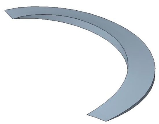
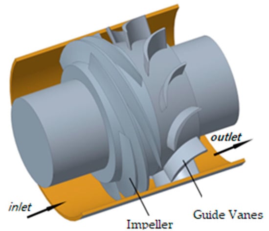
Figure 2 depicts the schematic diagram of a single-stage helical axial-flow mixed-flow pump, where a single-stage or a single compression unit consists of a helical axial-flow impeller and a fixed guide vane. The impeller blades are of typical helical shape, and the open impeller and guide vane structure are specifically designed to prevent the separation of the gas–liquid mixture during the compression process. The flow passage can accommodate solid particles suspended in the fluid. As the fluid mixture flows through the impeller, the impeller rotation performs work on it, thereby increasing its speed and angular momentum. Subsequently, the fixed guide vanes re-mix the incoming fluid and convert its kinetic energy into pressure energy.
2.2. Numerical Methods
2.2.1. Meshing and Independence Verification
The entire flow field adopts a structured grid. The overall flow passage grid for the impeller and guide vanes was established using ANSYS computational fluid dynamics Turbo Grid software (version 12.1). It is part of CFX and can create high-quality hexahedral grids while maintaining the underlying geometry, allowing for precise and rapid CFD analysis. Figure 3 shows the grid division of the entire boosting unit. Details of the grid near the leading and trailing edges are also displayed. The grid for the inlet duct and outlet expansion region was generated using ICEM CFD 16.0.
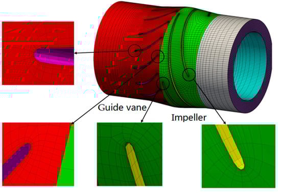
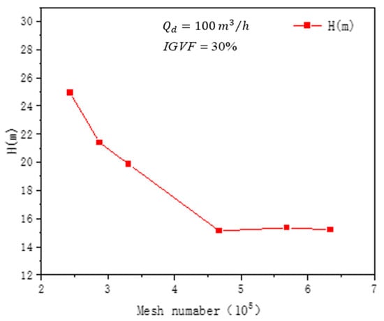
Considering the complex shapes of the impeller and guide vane surfaces, local refinement was applied, with boundary layers placed near the wall (y+ < 30), which generally meets the requirements of the turbulence model [33,34]. The criterion for grid independence was based on achieving stable head values at the design flow rate and a 30% inlet gas volume fraction. The initial mesh for the impeller consisted of approximately 200,000 cells, increasing by 100,000 cells thereafter. To mitigate the influence of grid size on computational results, grid independence was verified using six sets of grids with varying cell counts, as shown in Figure 4. Grid independence was assessed by stabilizing the pump head at the design flow rate and a 30% inlet gas volume fraction in multiphase flow. From Figure 4, it can be observed that the head deviation is within 0.05% when the number of cells exceeds 596,000. Considering numerical simulation accuracy and computational resources, the total mesh count for the entire computational domain was set to 596,000.
2.2.2. Numerical Methods
The computational software used in this article is Open-Source Field Operation and Manipulation (OpenFOAM). OpenFOAM is a C++-based executable program library, consisting of C++ classes. The applications in OpenFOAM are divided into two categories: solvers and utilities. Solvers are used to solve problems related to continuum mechanics, and utilities are used for data manipulation calculations. In this article, the InterFoam solver is adopted. This solver is based on the phase equilibrium model for cavitation, considering the compressibility of each phase, and it can be used to capture shock waves from bubble collapse.
InterFoam is an interface capturing solver based on the VOF (Volume of Fluid) model, used for capturing the interface between two phases that are incompressible, adiabatic, immiscible, and non-diffusing (where diffusion refers to one fluid being distributed within another, such as the movement of bubbles in a liquid). In the InterFoam solver, the capture of the free interface of the two-phase flow is achieved using the Volume of Fluid (VOF) method, and spatial discretization is carried out using the Finite Volume Method (FVM).
The interFoam solver in OpenFOAM is based on the VOF (Volume of Fluid) model and is used to solve for two-phase, incompressible flows. The governing equations are defined as follows:
The volume fraction equation. For the q-th phase, the volume fraction equation can be written as [35,36]
In the equation, and represent the density and volume fraction of phase , respectively; denotes the velocity of the mixed fluid; stands for the number of fluid species in the multiphase flow, i.e., the number of phases; represents the source term, which can be specified by the user in a customized manner and defaults to 0 if not specified; represents mass transfer from phase to phase ; and represents mass transfer from phase to phase . Both of these terms are 0 when there is no mass transfer between phases, but they are non-zero in cases of cavitation, vapor generation, or condensation, requiring a separate specification of the mass transfer mechanism.
In a total of -phase flow, it is sufficient to construct -1 equations like this for each secondary phase. This means that the VOF model does not solve the volume fraction equation for the primary phase. The volume fraction of the primary phase is obtained through the following equation:
The volume fraction equation can be solved using either explicit or implicit time integration schemes.
The momentum equation of the VOF model is as follows [36]:
where
- is the mixture density;
- is the dynamic viscosity of the mixture;
- is the mixture velocity;
- is the mixture pressure;
- is the acceleration of gravity;
- is the body force.
The energy equation of the VOF model is as follows [36]:
where
- ρ is the mixture density;
- keff is the effective thermal conductivity;
- τeff is the effective viscosity;
- Sh is the source phase;
- Jj is the diffusion flux of component j.
In the equation, parameters such as density ρ, effective thermal conductivity keff, and effective viscosity τeff are shared by all phases and calculated as the volume-weighted average of each phase. The original term Sh includes contributions from thermal radiation and other volumetric heat sources, and Jj represents the diffusion flux of grouping j. The three terms within the brackets on the right-hand side of the equation correspond, respectively, to energy transfer caused by conduction, component diffusion, and viscous dissipation. In the VOF model, the energy Eq (and temperature T) is calculated as the mass-weighted average of the energy of each phase E.
where Eq is the energy of each phase.
The VOF model relies on the premise that two or more fluids do not permeate each other, introducing volume fractions for each phase in the model as solving variables [37]. When using the VOF model, for the spatial discretization schemes of each term, the pressure term should preferably adopt the “PRESTO!” format or the Body Force Weight format, with the solid boundary adopting a no-slip boundary condition and the convergence accuracy set to 10−5. Firstly, based on the Euler–Euler heterogeneous flow model with the pressure outlet and velocity inlet as the boundary conditions, the continuous phase is water, and the discrete phase is air. Phase interactions are set up, including interfacial forces such as resistance, lift, virtual mass force, turbulent dissipation force, Saffman lift, Basset force, Magnus force, etc. Particularly under high Reynolds number flow conditions, the effects of Magnus force, virtual mass force, and Saffman lift are especially important, particularly effective when the particle diameter is between 1 and 10 μm. When studying the fluctuating characteristics of two-phase flow, and when the dimensionless frequency of the fluid is less than 0.5, the Basset force needs to be considered. When the density ratio between the fluid and the particles is greater than 0.1, additional mass force and pressure gradient force need to be emphasized. Therefore, to meet the uncertainties in transient simulation, the inclusion of the above interfacial forces greatly aids the accuracy of the simulation. The transient calculation time step is required for every 3° of impeller rotation, which is 1.68 × 10⁻⁴ s. The total time is the time needed for 8 cycles of impeller rotation.
2.3. Experimental Validation
Figure 5 shows the experimental platform system of the helical axial-flow multiphase pump, and Figure 6 illustrates a schematic diagram of the helical axial-flow multiphase pump experimental platform system. The testing system mainly consists of a multiphase pump, a variable frequency motor, a speed-torque meter, an air compressor, liquid regulating valve, gas regulating valve and flowmeter, inlet and outlet pressure transmitters, etc. The device in the experiment uses water and air. The gas is transported to the mixing device through a gas-phase pipeline by a compressor, and the liquid is injected into the mixing device through a liquid-phase pipeline from a high-pressure liquid storage tank. After uniform mixing inside the mixing device, the mixture is inputted into the inlet of the helical axial-flow multiphase pump. After pressurization by the boosting unit, it returns to the liquid storage tank through the outlet pipeline. There is a spherical valve on the outlet pipeline, which functions to discharge the gas contained in the outlet fluid, achieving the purpose of gas–liquid separation and liquid circulation. Therefore, during the experiment, the compressor continuously supplies gas to the system, and the liquid storage tank only needs to be filled with water once for internal liquid recycling. Through corresponding measuring devices, the external characteristics curve of the multiphase pump under different operating conditions, including pressure, flow rate, gas content, shaft power, and other related parameters, can be obtained.
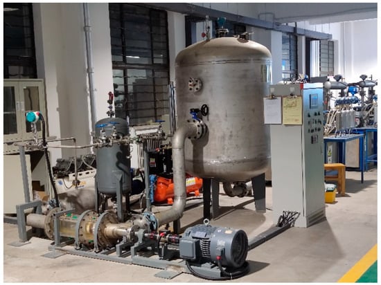
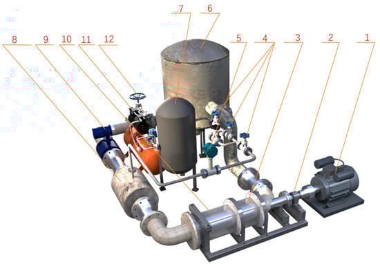
Figure 6.
Schematic diagram of spiral axial-flow multiphase pump test bench system. 1 Asynchronous motor; 2 torque measuring instrument; 3 model pump; 4 gas inlet valve; 5 vortex flowmeter; 6 water storage tank; 7 high-pressure gas storage tank; 8 gas–liquid mixer; 9 electromagnetic flowmeter; 10 mixed pump inlet section; 11 air compressor; 12 liquid inlet valve.
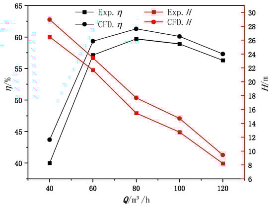
The performance curves obtained from numerical simulations at different flow rates with IGVF = 30% are compared with experimental results, as shown in Figure 7. It can be seen from the figure that the performance curves obtained from numerical simulations exhibit the same trend as the experimental curves. However, the numerical simulation does not take into account mechanical and volumetric losses, leading to some errors compared to experimental results, with a maximum head error of 6.7% and a maximum efficiency error of 8.9%. Under design conditions, the head error is 4.3%, and the efficiency error is 5.9%. Therefore, the numerical simulation method and grid model adopted in this study demonstrate a certain degree of reliability.
3. Analysis of Results
In the impeller passage of the gas–liquid mixed flow pump, due to the rotation of the impeller, phase separation occurs between the gas and liquid phases, causing the gas bubbles to move towards the hub of the impeller, while the liquid moves towards the impeller shroud. When the gas bubbles reach the hub of the impeller, they cannot be promptly transported out of the impeller, and they accumulate on the impeller hub wall. With the gathering and merging of bubbles, one or more large gas clusters form and remain in the impeller passage, leading to impeller passage blockage. Studying the mechanism of impeller passage blockage provides reliable theoretical guidance for how to solve the blockage caused by gas–liquid phase separation in the impeller passage and design efficient anti-blockage impellers.
Regarding the blockage of the impeller passage by gas clusters, it occurs based on the phase separation of the gas–liquid two-phase flow. With a low bubble density, as the impeller continuously rotates, the bubbles are expelled by the liquid phase. Under the dominance of pressure gradient forces, the bubbles move towards the hub of the impeller and gather and combine on the hub surface.
T in the following is the time for the impeller to rotate once. I mainly take the impeller to rotate once and analyze the changes at different moments during the rotation week.
3.1. Accumulation of Bubbles in Impeller Runner
In order to gain a clearer understanding of the changes in the gas phase within the impeller passage, Figure 8 illustrates the distribution changes in the gas-phase volume fraction on the hub surface within one rotation cycle T of the impeller, under the condition of gas volume fraction (GVF) = 0.3 at the impeller inlet. From the figure, it can be observed that initially, bubbles gather near the hub of the impeller outlet close to the pressure side of the blade, in the region between two adjacent non-overlapping blade passages. As the continuous separation of gas–liquid phases occurs, bubbles continuously move towards the impeller hub. Bubbles gradually accumulate and merge, and they begin to spread and extend along the pressure side of the blade, eventually bypassing the trailing edge of the blade and combining with gas masses in adjacent passages, thereby forming gas masses that block the passage. Initially, there is no significant gas-phase accumulation phenomenon within the guide vane passage. However, with time, gas-phase fluid medium exiting from the impeller enters the guide vane, and the gas accumulation area near the suction side of the guide vane passage continuously increases, eventually occupying the entire passage. In the initial stages of flow, there is a noticeable high-gas region near the hub at the outlet of the guide vane suction side. This region gradually disappears after a certain number of cycles because, in the initial stages of flow, due to the phenomenon of gas accumulation inside the impeller, there is not much gas entering the guide vane. This causes the remaining kinetic energy of the liquid phase to gradually expel the small amount of gas towards the impeller hub, reaching its maximum value at the outlet end of the suction side, causing a large accumulation of gas at that position. As the flow cycle increases, the amount of gas entering the guide vane gradually increases, and the kinetic energy of the liquid gradually weakens. The degree of mixing between the gas and liquid phases also increases, causing the amount of gas expelled to the hub position to decrease gradually. These phenomena indicate that the distribution of gas-phase fluid medium in the compression unit changes over time, and gas accumulation phenomena occur within both the impeller and the guide vane.
3.2. Analysis of Vortex Motion in Mixed Transport Pump
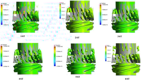
Figure 9 describes the changes in the vortex within a single compression stage at different flow moments. It captures the formation of vortices within the gas passages using the Q criterion (Q value = 134,605 s−2) and colors the entire vortex interface with the void fraction [38,39,40,41]. Q values are defined as follows:
where Ω is the vorticity tensor, and E is the strain rate tensor.
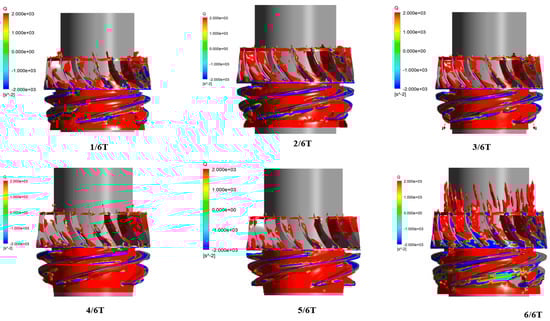
It can be observed that with the increase in flow cycles, the volume of vortices within the entire compression stage also increases correspondingly. Within the impeller, the vortex widens radially outward from the hub, and within the guide vanes, it extends longitudinally along the axial direction. The distribution of the gas phase within the impeller passage is relatively clear, with a narrow strip-like gas volume region observed near the hub of the impeller. As shown in the gray rectangular box in Figure 8, this strip-like gas volume is approximately parallel to the impeller blades and extends to the leading edge of the guide vanes. From 1/6T to 6/6T, in a typical rotation cycle, the morphology of this strip-like gas volume slightly changes, indicating that the strip-like gas volume near the hub is influenced by the work performed by the impeller blades. At 6/6T, as the gas volume enters the guide vane passage, its development becomes more complex. At the inlet of the impeller passage near the suction surface, there is an uneven distribution of vortex magnitude, as shown in the gray elliptical box in the figure. This is because initially, as the medium passes through the impeller from rest, kinetic energy is generated, resulting in significant disturbances in the medium entering the impeller due to previous disturbances in the inlet pipe and the interference between the moving and stationary parts of the impeller, causing the subsequent distribution of vortex magnitude in the impeller to become uneven. As the running time within the impeller passage increases, the flow tends to stabilize.
At the initial stage of flow, with a gas content of 30%, an elliptical strip-like vortex appears inside the guide vane passage, extending axially from the inlet of the guide vane, occupying roughly half of the passage. The front end of the vortex starts from the leading edge of the back surface of the guide vane, then expands almost horizontally from the back surface of the guide vane towards the working surface, with the tail connecting to the geometric center of the working surface edge, where the gas content is at its maximum for the entire compression unit. Its axial direction is almost parallel to the guide vane blades. Apart from a small amount of wake appearing at the exit of the guide vane, there are no other vortices inside the guide vane. It can be observed that at 6/6T, the gas-phase vortex almost fills the entire guide vane passage. This is because in the initial stage, due to gas–liquid expulsion and adverse pressure gradient forces, gas is accumulated at the hub of the impeller. Under the continuous work of the impeller, it momentarily breaks through the adverse pressure gradient forces, surging out of the impeller and entering the guide vane. As the liquid flows out of the guide vane and into the exit section, it is also filled with various sizes of gas pockets.
3.3. Blockage of Impeller Runner by Air Mass
Bubbles gather and merge inside the impeller passage to form large gas clusters, which cannot be promptly transported out of the passage, resulting in the clusters lingering and blocking the passage. This section explores the reasons behind this phenomenon through numerical calculations.
If the gas clusters cannot be transported out of the passage, there must be a force hindering them. This force needs to counteract the pressure generated by the work performed by the impeller on the fluid, thereby allowing the gas clusters to remain in the passage. The same mixed-flow pump impeller performs work on fluids of a pure liquid phase, a gas–liquid mixed phase, and a pure gas phase under identical rotational speed and inlet conditions. At the outlet of the impeller passage, the static pressure formed by the conversion of kinetic energy into pressure energy ranks as follows: pure liquid > gas–liquid mixed phase > pure gas.
Figure 10 shows the distribution of pressure within the passages of the impeller and guide vane at different blade heights during one rotation cycle T of the impeller. During the initial stage of impeller rotation, when the blade profile of the impeller has not established sufficient pressure, the work performed by the impeller on the gas phase (kinetic energy + potential energy) is converted into part of the potential energy of pressure. Near the trailing edge of the impeller blade, the pressure equals the trailing edge pressure of the mixed medium, allowing the gas-phase medium to be smoothly transported out by the impeller. In the case of a mixed-flow pump transporting a gas–liquid two-phase mixed medium, due to the phase separation of the gas–liquid two phases, bubbles continue to accumulate and coalesce in the passage, resulting in the gas volume fraction near the hub of the pressure surface of the impeller blades in the non-coincidence region being greater than that of the initial mixed phase. This leads to the pressure at this position being lower than the suction surface pressure of the blade trailing edge, where the liquid-phase volume fraction slightly predominates due to gas–liquid separation, thus inducing the initial adverse pressure gradient of gas blockage and the gas pocket vortex.
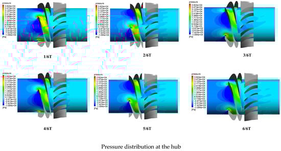
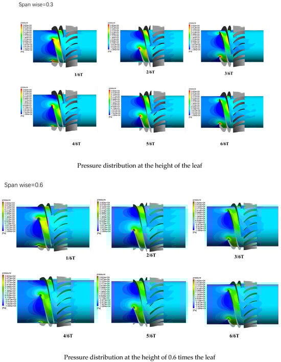
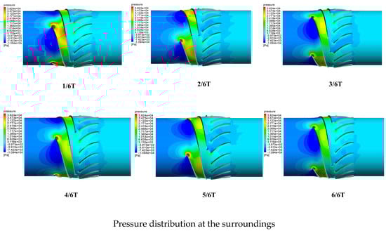
Figure 10.
Pressure distribution of different blade heights in the rotating flow path of a periodic impeller and guide vane.
As time progresses, the continuous separation of the gas–liquid phases leads to an increasing gas volume fraction at the hub of the impeller, and the density of the mixed-fluid medium decreases. With the ongoing separation of the gas and liquid phases within the impeller, more bubbles are expelled to the trailing edge of the pressure surface of the hub-side impeller blades. The pressure at this location gradually decreases and tends towards the pressure at the trailing edge of the blade when it predominantly consists of a pure gas phase. Hence, the adverse pressure gradient at this location becomes increasingly significant. Figure 11 depicts the pressure values at the hub of the impeller’s pressure surface over one rotation cycle T under different rotational speeds. The work performed by the impeller on the mixed fluid at the hub noticeably decreases, and after λ = 0.2, it becomes smaller than the static pressure formed by the impeller flow passage.
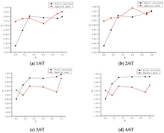
To provide a more intuitive expression of the principle behind gas clusters blocking the passage, we can use ∆P to represent the degree of blockage caused by the gas clusters:
where represents the work performed by the impeller to the fluid at any particle in the flow channel, and represents the static pressure of the flow channel at downstream of the same flow line at particle .
When < 0, it indicates that the impeller overcomes the static pressure downstream of the flow passage, allowing the fluid to be output from the impeller.
When ≥ 0, it indicates that the work performed by the impeller on the fluid is less than or equal to the downstream static pressure of the flow channel, unable to overcome the static pressure. Consequently, fluid microcosms in the flow channel experience deceleration or come to a halt in the direction of flow. In the non-overlapping region of the impeller flow channel, severe gas–liquid separation occurs, leading to localized low pressure at gas cluster aggregation points. The motion speed of gas bubbles is further reduced, resulting in an increase in the volume of gas clusters in these areas.
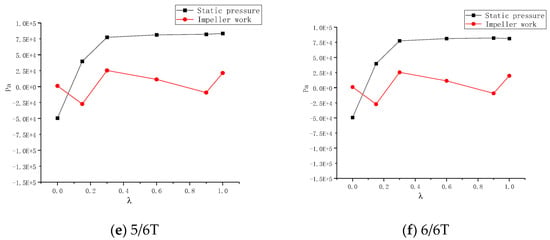
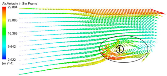
Due to insufficient confinement of fluid by the interphase shear flow induction and non-coincident area between the impeller and blades, significant axial vortices are formed at this location, as shown in Figure 12①. The vortices occur in two locations: one at the hub of the pressure surface, where bubbles initially aggregate and combine in the non-coincident area of the blade, and the other at the hub near the trailing edge of the blade on the suction surface side, as shown in Figure 13. The rotational motion of the axial vortices around the exit area of the impeller flow passage intensifies the phase separation of the gas–liquid two-phase flow, accelerating the movement of liquid from the bubble vortex towards the impeller periphery. The bubbles accumulating at the impeller hub continuously increase, eventually reaching a dynamic balance, with bubbles continuously supplementing and releasing from the bubble cluster. The presence of the bubble vortex makes it difficult for bubble clusters to be transported out of the impeller. The flow passage at the impeller hub narrows, is deformed, or becomes blocked, whereas the flow passage away from the hub is less prone to blockage due to the strong functional force of the impeller and the high density of the mixed-fluid medium. Eventually, the impeller periphery and hub form two-phase separated states, predominantly consisting of pure liquid-phase medium and pure gas-phase medium, respectively.
4. Conclusions
Through the above studies, the mechanism of gas blockage in the impeller passage of the gas–liquid mixed transportation pump can be summarized as follows:
(1) The phase separation of gas and liquid in the impeller passage of the gas–liquid mixed transportation pump causes bubbles and liquid to move towards the hub and shroud the sides of the impeller, respectively. Bubbles gradually gather and combine at the hub of the impeller passage to form relatively large gas clusters, providing the first condition for cluster blockage.
(2) Due to the intensified phase separation of gas and liquid in the tail section of the impeller passage of the gas–liquid mixed transportation pump, the pressure on the liquid-phase accumulation side of the blade trailing edge is much higher than the pressure on the gas-phase accumulation side on the other side, forming a phenomenon of an overpressure gradient in the adjacent flow passage of the gas phase, providing the second condition for cluster blockage.
(3) At the same impeller speed, the work performed by the impeller on the gas cluster is not enough to overcome the reverse pressure gradient generated by the liquid-phase accumulation in the adjacent flow passage of the blade trailing edge, preventing the gas cluster from flowing out of the flow passage. This leads to the formation of shear flow between the gas cluster and the fluid, with a higher volume fraction of the liquid phase at the outer edge of the gas cluster, gradually forming a dynamically balanced vortex gas cluster near the outlet of the passage and blocking the flow passage.
To sum up, the difference in gas–liquid two-phase density and the adverse pressure gradient in the pipeline are the important reasons for the formation of gas blockage in the gas–liquid mixed transport system. These factors affect the distribution and flow characteristics of the gas–liquid two phases in the pipeline. In practical engineering applications, this phenomenon will be more obvious, so it is very important to study and eliminate the gas blocking phenomenon caused by gas–liquid mixed transport.
Author Contributions
Conceptualization, S.Z. and T.X.; methodology, W.H.; software, J.M.; validation, P.Q.; formal analysis, W.H.; investigation, S.Z.; resources, R.L. and S.Z.; data curation, J.M.; writing—original draft preparation, W.H.; writing—review and editing, P.Q.; visualization, T.X.; supervision, S.Z.; project administration, R.L.; funding acquisition, R.L. All authors have read and agreed to the published version of the manuscript.
Funding
Gansu Provincial Department of Education: University Research Innovation platform major cultivation project 2024CXPT-09.
Data Availability Statement
All data in this manuscript are available from the corresponding author by e-mail.
Acknowledgments
This study was supported by The National Natural Science Foundation of China (52179086, 52269022) Open Research Subject of Key Laboratory of Fluid Machinery and Engineering (Xihua University), Sichuan Province (Grant No. LTJX-2023003), Gansu Provincial Department of Education: University Research Innovation platform major cultivation project 2024CXPT-09.
Conflicts of Interest
Author Jiandong Mi was employed by the company Shaanxi Aerospace Power Hi-Tech Co., Ltd. The remaining authors declare that the research was conducted in the absence of any commercial or financial relationships that could be construed as a potential conflict of interest.
References
- Feng, S. A preliminary understanding of multi-phase mixed transport pumps. Oil Gas Field Surf. Eng. 1995, 14, 3. [Google Scholar]
- Wang, Y. Review of multi-phase pump and multi-phase flow mixed transport technology abroad. Oil Gas Field Surf. Eng. 1996, 15, 7. [Google Scholar]
- Zhang, W.; Xue, D. Research progress of multiphase flow pumps abroad. Pump Technol. 1995, 6, 7. [Google Scholar]
- Yu, X.; Zhao, J.; Wu, Y. Research on oil-gas-water multiphase pipe flow technology at home and abroad. China Offshore Oil Gas 2002, 14, 7. [Google Scholar]
- Yong, W.; Dong, W. Development, design and economic evaluation of Poseidon p302 multiphase pump. Nat. Gas Oil 1997, 15, 6. [Google Scholar]
- Xu, F.; Fang, J.; Zhao, F. Optimization and experimental study of Structural parameters of spiral axial flow oil and gas mixed transport pump. J. Oil Gas Technol. 2005, 5, 833–835. [Google Scholar]
- Zhao, X. Experimental Study on Gas-Liquid Two-Phase Characteristics of Spiral Axial Flow Multi-Phase Mixed Transport Pump. Master’s Thesis, China University of Petroleum (East China), Dongying, China, 2007. [Google Scholar]
- Li, X. Development and Experiment of Spiral Axial Flow Oil and Gas Mixed Transport Pump. Southwest Petroleum University: Chengdu, China, 2014. [Google Scholar]
- Chen, S. Analysis and Experimental Study of Flow Field in Water Chamber of Axial Flow Oil and Gas Mixed Transport Pump. 2002. [Google Scholar]
- Liu, X. External Characteristic Test and Numerical Simulation of Spiral Axial Flow Multiphase Pump. China University of Petroleum, Beijing, China, 2009. [Google Scholar]
- Zhang, J.; Cai, S.; Zhu, H.; Qiang, R. Experimental Study of Gas-Liquid Two-Phase Flow Pattern in a Helico-Axial Multiphase Pump by Visualization. J. Eng. Thermophys. 2015, 36, 1937–1941. [Google Scholar]
- Zhu, R.; Lin, P.; Wang, Z.; Long, Y. Design and experiment for screw axial-flow pumps. J. Huazhong Univ. Sci. Technol. 2013. [Google Scholar] [CrossRef]
- Zhang, J.; Cai, S.; Li, Y.; Zhu, H.; Zhang, Y. Optimization design of multiphase pump impeller based on combined genetic algorithm and boundary vortex flux diagnosis. J. Hydrodyn. Ser. B 2017, 29, 1023–1034. [Google Scholar] [CrossRef]
- Zhang, J.; Zhu, H.; Wei, H. Three-Dimensional Blade Design of Helico-Axial Multiphase Pump Impeller Based on Numerical Solution of Meridian Flow Net and Blade Mean Camber Lines. In Proceedings of the ASME-JSME-KSME 2011 Joint Fluids Engineering Conference, Hamamatsu, Japan, 24–29 July 2011; pp. 163–170. [Google Scholar]
- Liu, M.; Cao, S.; Cao, S. Numerical analysis for interphase forces of gas-liquid flow in a multiphase pump. Eng. Comput. 2018, 35, 2386–2402. [Google Scholar] [CrossRef]
- Yu, Z.; Zhu, B.; Cao, S. Interphase force analysis for air-water bubbly flow in a multiphase rotodynamic pump. Eng. Comput. 2015, 32, 2166–2180. [Google Scholar] [CrossRef]
- Yu, Z.; Zhu, B.; Cao, S.; Liu, Y. Effect of Virtual Mass Force on the Mixed Transport Process in a Multiphase Rotodynamic Pump. Adv. Mech. Eng. 2015, 6, 958352. [Google Scholar] [CrossRef]
- Zhang, J.; Cai, S.; Li, Y.; Zhu, H.; Zhang, Y. Visualization study of gas–liquid two-phase flow patterns inside a three-stage rotodynamic multiphase pump. Exp. Therm. Fluid Sci. 2016, 70, 125–138. [Google Scholar] [CrossRef]
- Murakami, M.; Minemura, K. Behavior of air bubbles in an axial-flow pump impeller. J. Fluids Eng. 1983, 105, 277–283. [Google Scholar] [CrossRef]
- Minemura, K.; Murakami, M. A theoretical study on air bubble motion in a centrifugal pump impeller. J. Fluids Eng. 1980, 102, 446–453. [Google Scholar] [CrossRef]
- Minemura, K.; Uchiyama, T. Three-Dimension Calculation of Air-Water Two-Phase Flow in Centrifugal Pump Impeller Based on a Bubby Flow Model with Fixed Cavity. JSME Intern. J. Ser. B 1994, 37, 726–735. [Google Scholar] [CrossRef]
- Minemura, K.; Uchiyama, T.; Shoda, S.; Egashira, K. Prediction of Air-Water Two-Phase Flow Performance of a Centrifugal Pump Based on One-Dimensional Two-Fluid Model. J. Fluids Eng. Trans. Asme 1998, 120, 327–334. [Google Scholar] [CrossRef]
- Van Sint Annaland, M.; Deen, N.G.; Kuipers, J.A.M. Numerical simulation of gas bubbles behaviour using a three-dimensional volume of fluid method. Chem. Eng. Sci. 2005, 60, 2999–3011. [Google Scholar] [CrossRef]
- Yu, Z.; Cao, S.; Wang, G. Three-dimensional numerical model of gas-liquid two-phase flow in a vane pump. J. Beijing Inst. Technol. 2007, 27, 1057–1060. [Google Scholar]
- Yu, Z.; Cao, S.; Wang, G. Numerical calculation of gas-liquid two-phase flow in a vane mixed transport pump. Chin. J. Eng. Thermophys. 2007, 28, 3. [Google Scholar]
- Pang, C.; Yuan, S. Geometric and Dynamic Characteristics of bubbles in cross flow. J. Drain. Irrig. Mach. Eng. 2020, 38, 1023–1029. [Google Scholar]
- Numerical Modeling; Studies from Tsinghua University Have Provided NewData on Numerical Modeling (Numerical analysis for interphase forces of gas-liquid flow in a multiphase pump). J. Technol. Sci. 2018.
- Li, Q.; Xue, D. Study on phase separation process in vane multiphase pump. J. China Univ. Pet. (Ed. Nat. Sci.) 1997, 3, 53–56. [Google Scholar]
- Huang, S.; Wu, Y. Three-dimensional Numerical Calculation of gas-liquid Two-phase bubble Flow in Vane Pump. J. Hydraul. Eng. 2001, 5, 57–61. [Google Scholar]
- Zhang, K. Numerical Study on Reconfiguration and Internal Two-Phase Flow Characteristics of Gas-Liquid Mixed Transport Pump. Xi’an University of Technology University, Xi’an, Chana, 2019. [Google Scholar]
- Wang, C. Parametric 3D Modeling and Wear Characteristics Analysis of Mixed-Flow Desulfurization Pump. North China Electric Power University, Beijing, China, 2010. [Google Scholar]
- Yang, H. Numerical Simulation of Gas-Liquid Two-Phase Flow in Pneumatic Lifting Pump. Xi’an University of Technology: Xi’an, Chana, 2020. [Google Scholar]
- Li, W.; Li, Z.; Han, W.; Li, Y.; Yan, S.; Zhao, Q.; Gu, Z. Pumping-velocity variation mechanisms of a ferrofluid micropump and structural optimization for reflow inhibition. Phys. Fluids 2023, 35, 052005. [Google Scholar]
- Wang, J.; Zha, H.; McDonough, J.M.; Zhang, D. Analysis and numerical simulation of a novel gas–liquid multiphase scroll pump. Int. J. Heat Mass Transf. 2015, 91, 27–36. [Google Scholar] [CrossRef]
- Hirt, C.W.; Nichols, B.D. Volume of fluid (VOF) method for the dynamics of free boundaries. J. Comput. Phys. 1981, 39, 201–225. [Google Scholar] [CrossRef]
- ANSYS Inc. ANSY Fluent Theory Guide; ANSYS Inc.: Canonsburg, PA, USA, 2018. [Google Scholar]
- de Salis, J.; Cordner, M.; Birnov, M. Multiphase pumping comes of age. World Pumps 1998, 1998, 53–54. [Google Scholar] [CrossRef]
- Zhang, Y.N.; Qiu, X.; Chen, F.P.; Liu, K.H.; Zhang, Y.N.; Dong, X.R.; Liu, C.Q. A selected review of vortex identification methods with applications. J. Hydrodyn. 2018, 30, 767–779. [Google Scholar] [CrossRef]
- Zhang, Y.N.; Liu, K.H.; Xian, H.Z.; Du, X. A review of methods for vortex identification in hydroturbines. Renew. Sustain. Energy Rev. 2018, 81, 1269–1285. [Google Scholar] [CrossRef]
- Zhang, Y.N.; Zhang, Y.N.; Wu, Y.L. A review of rotating stall in reversible pump turbine. Proc. Inst. Mech. Eng. Part C J. Mech. Eng. Sci. 2017, 231, 1181–1204. [Google Scholar] [CrossRef]
- Zhang, Y.N.; Zheng, X.H.; Li, J.W.; Du, X. Experimental study on the vibrational performance and its physical origins of a prototype reversible pump turbine in the pumped hydro energy storage power station. Renew. Energy 2019, 130, 667–676. [Google Scholar] [CrossRef]
Disclaimer/Publisher’s Note: The statements, opinions and data contained in all publications are solely those of the individual author(s) and contributor(s) and not of MDPI and/or the editor(s). MDPI and/or the editor(s) disclaim responsibility for any injury to people or property resulting from any ideas, methods, instructions or products referred to in the content. |
© 2024 by the authors. Licensee MDPI, Basel, Switzerland. This article is an open access article distributed under the terms and conditions of the Creative Commons Attribution (CC BY) license (https://creativecommons.org/licenses/by/4.0/).