Abstract
Cyclone separation is a widely utilized separation technique, which enables the self-rotation behaviors of particles in the internal flow field, in order to realize high-performance separation of mixtures. Oily sludges are solid wastes generated by the shale gas industry, which need to be properly treated for environmental protection. In the present investigation, we demonstrated that tuning the inlet flow pattern of the cyclone from linear flow to vortex flow is an effective approach to boost the rotation speed of oily sludge particles for obtaining significantly improved separation effects. Numerical simulations were carried out to investigate the influences of inlet flow pattern on the rotation behaviors of particles, which manifested in the rotation speed of particles being evidently increased up to 4500 rad/s when the inlet flow was tuned from a unidirectional pattern into vortex pattern. The effective rotation zone’s area was also found to increase significantly, with the area of the effective rotation zone enlarged by up to 400%. Further separation experiments on oily sludge were carried out using a cyclone equipped with a worm shell that generated vortex inlet flow with rotating blades. Separation results confirmed that the oily sludge was successfully purified by the cyclone equipped with a worm shell, which provided an extremely high oil removal percentage of 99.9%, showing a 49.1% enhancement in oil removal capability over the individual cyclone separation. Our investigations demonstrated an effective method for realizing oily sludge treatment and oil resource recovery by conventional cyclone separation.
1. Introduction
Cyclone separation is one of the most frequently used separation techniques in chemical engineering, which provides the distinctive advantages of high separation efficiency, continuous processing capability, and cost-effectiveness [1,2,3]. For a typical cyclone separation, an inlet flow brings the target mixture into the cyclone to provide it with angular momentum, which is capable of separating the mixture by relying on the density-determined centrifugal force differences between substances in the internal flow field of the cyclone. Under centrifugal force, heavier particles rotate along a larger radius near the outer wall of the cyclone and eventually slide to the bottom for collection, while lighter particles rotate up along a smaller radius and are expelled from the top, central area. This phenomenon leads to the formation of a Rankine vortex, which is characterized by a forced vortex in the central core and a free vortex that increases with distance from the center [4,5,6,7]. Based on these characteristics, cyclone has proven to be effective for the separation of a wide range of multiphase mixtures, including gas–liquid [8,9,10], gas–solid [11,12,13], solid–liquid [14,15,16], and liquid–liquid [17,18] mixtures.
Most studies related to cyclone separators are focused on the separation performance, pressure drop, cut-off size, effect of geometrical parameters, etc. [1,19,20,21]. Additionally, research has shown that particles within the flow field inside a cyclone separator not only undergo orbital motion, but also experience self-rotation due to the influence of unbalanced forces [22]. As regards purification, the rotation of particles promotes the desorption of pollutants adsorbed on the particle surface into the gas phase and their subsequent discharge with the gas phase, which indicates that cyclone separation is an effective approach applicable to the purification of contaminated particles [23]. In this regard, the rotation speed of particles in the flow field is considered to be one of the most important factors to determine the purification capability of cyclone separation. As a consequence, a novel design for cyclone separation is proposed by adding a worm shell with rotating blades in front of the cyclone inlet to accomplish high-permanence purification of oily sludges that are solid wastes generated by the shale gas industry. The purpose of rotating blades is to generate inlet vortex flow into the cyclone, which is believed to enhance the rotation speed of the particles and to increase the area of the high-speed region in the cyclone separator. Moreover, inlet vortex flow is supposed to improve the distribution of particles in the internal flow field of the cyclone to prevent aggregation of particles and to improve the treatment capacity.
In the present investigation, the numerical simulations of cyclone separation were carried out by using a unidirectional inlet flow pattern and vortex inlet pattern, respectively, and the comparisons of the simulation results demonstrated the critical role of tuned inlet flow patterns for the boosted rotation speeds of particles in the flow field of a cyclone [24,25]. Further separation experiments with oily sludges were carried out with the cyclone that was equipped with a worm shell to generate the vortex inlet into the cyclone. The separation results confirmed the effectiveness of the tuned inlet flow pattern for realizing high-performance purification of oily pollutant from the oily sludges. A total of 99.9% of the oily pollutant was recovered from the oily sludges with cyclone separation using vortex inlet flow, which showed a 49.1% enhancement in the oil separation efficiency over the cyclone separation using unidirectional inlet flow.
2. Materials and Methods
2.1. Numerical Simulation Experiments
2.1.1. Cyclone Model
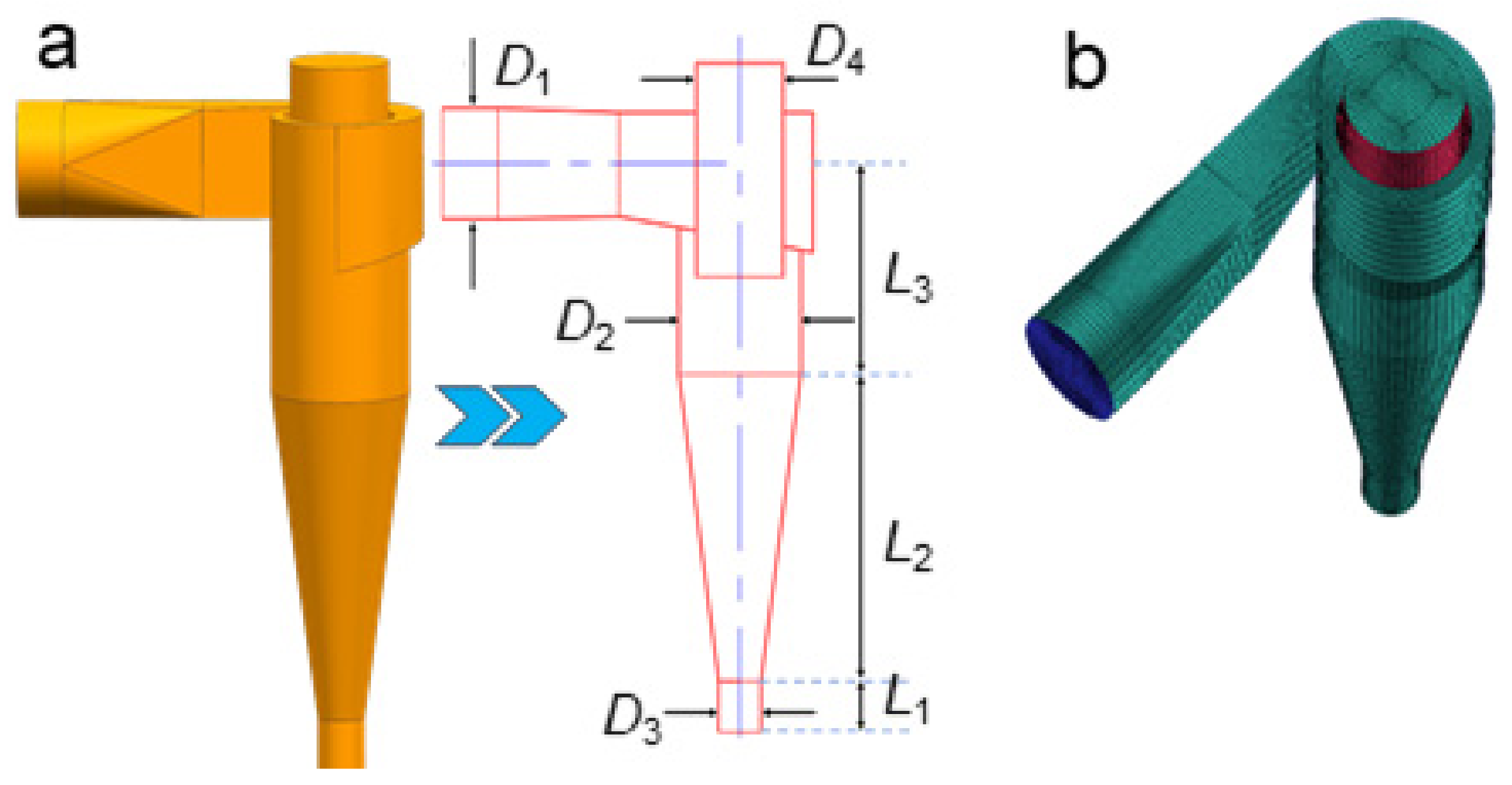
The cyclone model consists of the following main parts: a circular inlet pipe, rectangular volute, cylindrical section, conical section, particle collector and upper outlet, as shown in Figure 1a. Table A1 shows the geometrical parameters of the cyclone model. A structured mesh is employed to discretize the cyclone model. The mesh is generated by a bottom-up method. Due to the strong velocity gradient near the wall, all boundary layer meshes are refined.

Figure 1.
The cyclone model established for numerical simulations. (a): Model and scale of cyclone, (b): Mesh setup.
2.1.2. Computational Equation
The fluid is set as a gas–solid two-phase fluid. In general, fluid motion needs to be solved first, and then the solid phase is added to the solved flow field to obtain the final two-phase flow field (i.e., the coupled calculation). In gas–solid two-phase fluids, the gas, as a continuous phase, moves according to the basic hydrodynamic equations, and the continuity equation is given in Equation (1):
where ρg is the density of gas, and subscript i represents direction, and the momentum Equation (2) is shown as below:
where , and represent the average velocity and pressure in each direction, respectively. and are the velocity fluctuations in two directions, and where m is dynamic viscosity.
The momentum equation in the computational fluid dynamics (CFD) calculation is represented by Navier–Stokes equations (N-S equations). To solve N-S equations, a turbulence model is necessary. The flow field of the cyclone is a typical three-dimensional rotating flow, and the Reynolds stress model (RSM) is selected because the model has been verified in many numerical calculations on cyclone [26,27]. The transport Equation (3) is shown below [28,29]:
where u represents velocity fluctuation, and i, j and k denote the three-dimensional orientations. Dij, φij, Gij, εij, and S represent the diffusion term, the pressure strain term, the production term, the dissipation term, and the user-defined source term, respectively, which are defined as follows:
The particles act as discrete phases, which are injected into the flow field by means of a discrete phase model (DPM). The trajectories of the particles can be obtained by integrating the forces acting on the particles with the following force balance Equation (4):
where FD(ug − uP) stands for the drag force and the subscripts g and P stand for gas and particles, respectively. F is the sum of the forces acting on the particles, and FD depends on the diameter of the particles and introduces the following empirical Equation (5):
where dP is the diameter of particle, CD is drag force coefficient, which can be obtained from the methods provided by Morsi and Alexander [30] or Haider and Levenspiel [31]. Re is the relative Reynolds number defined in Equation (6):
2.1.3. Boundary Conditions and Simulation Setting
The inlet velocity of the gas phase is calculated according to the volume flow and the inlet cross-sectional area. The outlet condition is specified as atmospheric pressure. All wall surfaces were defined as non-slip walls. The solid phase density is measured to be 1550 kg/m3 and the particle diameters range from 0.01 mm~0.1 mm. Particles enter the cyclone through the inlet at the same velocity as the gas, and are considered to escape when the particles move to the outlet (upward and downward). Surface injection is adopted as the particle injection boundary condition, in which ~9000 particles are specified and are equally distributed at the inlet surface. Collisions between the wall and the particles are assumed to be elastic. The coupling of the velocity and pressure fields is implemented using the SIMPLEC (Semi-implicit Pressure Link Equation Method) algorithm, and the PRESTO method is used for the pressure interpolation scheme. The commercial software FLUENT (ANSYS STUDENT 2024 R1) is used for steady-state calculations and the convergence criterion is set to 1 × 10⁻⁵.
2.2. Cyclone Separation of Oily Sludges
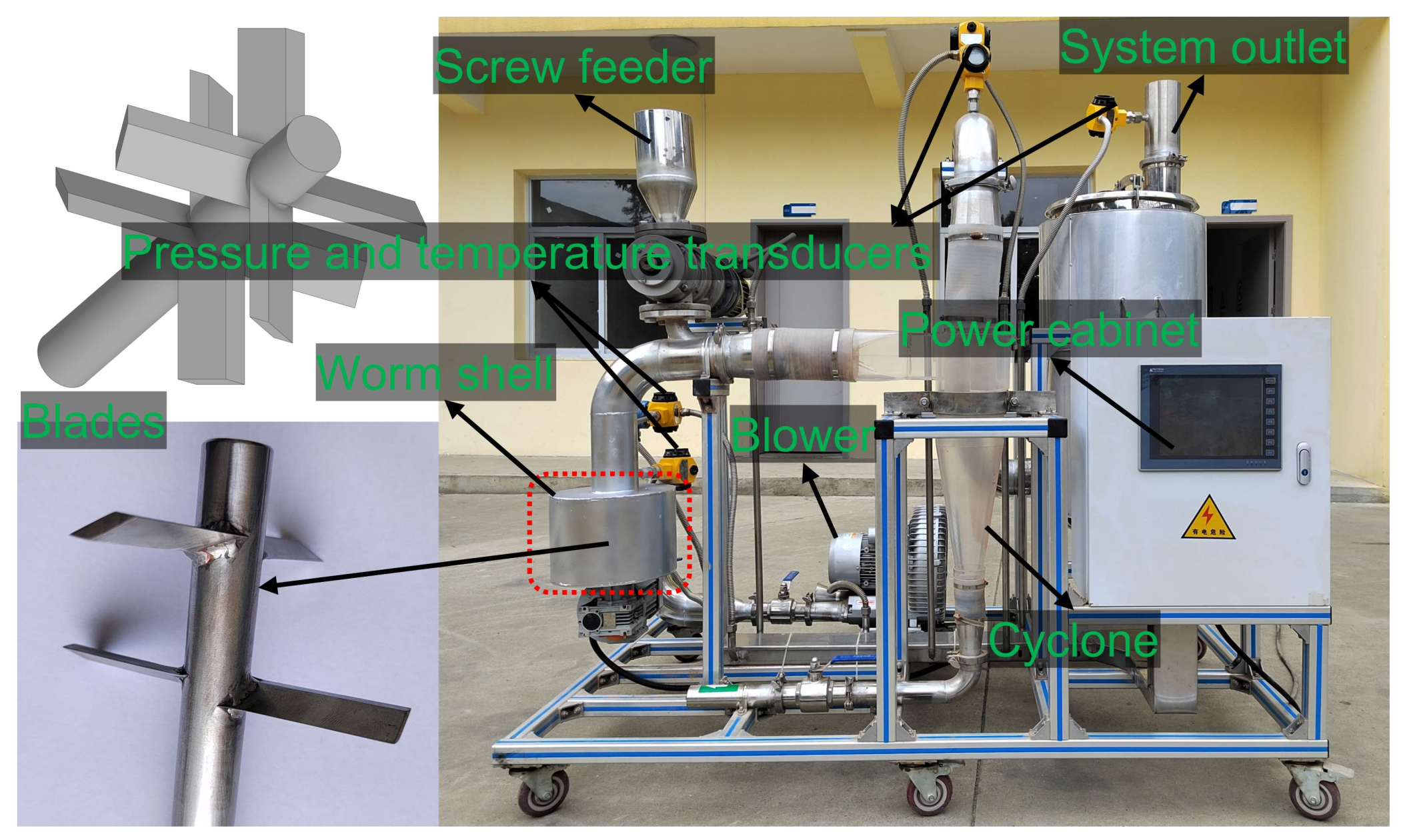
Cyclone separation of oily sludges was carried out to validate the results of the numerical simulations. As shown in Figure 2, the cyclone separation equipment consists of a cyclone and a worm shell that is equipped in front of the cyclone to generate vortex inlet flow with rotating blades. The details of the apparatus are listed in Table A2. As for the cyclone separation, a blower was used to provide the required gas, and the gas flow was controlled by a valve mounted behind the outlet of the blower. Oily sludges are fed through a screw feeder to transport them into the worm shell, and then the gas–oily sludge mixture enters into the internal flow field of the cyclone to cause separation. After the cyclone separation, the already-separated sludges were collected at the bottom outlet, and the gas phase exited the separator through the upper gas outlet. For comparison, the separation of oily sludges was also carried out with the cyclone without the worm shell. The experimental conditions for the separation of oily sludges were set with the inlet pressure of 1.0 ± 0.1 kPa, and inlet flow volume of 220–225 m3 h−1.
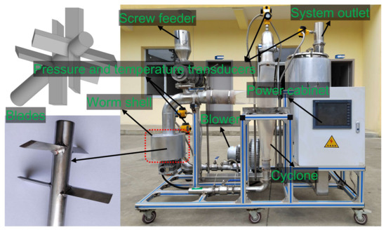
Figure 2.
The cyclone equipment used for the separation of oily sludges.
The inlet pressure (Pin,measure) is measured at a certain distance upstream of the screw feeder. Taking into account the local resistance loss (ΔPl) caused by the elbow piping between the measurement point and the prototype inlet, and the friction loss along the piping (ΔPf), the actual inlet pressure (Pin,EXP) of the cyclone is reduced from the measured value, which was calculated using the following Equation (7):
The friction loss and local loss are estimated as follows:
Friction loss:
Local loss:
λ and ζ are the friction loss coefficient and local loss coefficient, respectively, l is the distance from the inlet pressure transducer to the cyclone inlet, d is the pipe diameter, ρ is the fluid density, and u is the flow velocity. As for the laminar flow, the friction loss coefficient depends on the Reynolds number—Re—which is equal to 64/Re. However, if the magnitude of Re is around 1 × 10⁵, then the friction loss coefficient is determined using the Moody diagram. Based on above considerations, the pressure drop between the inlet and outlet of the cyclone separation is calculated as follows:
where Pout,EXP represents the measured outlet pressure.
3. Results and Discussion
3.1. Numerical Simulation
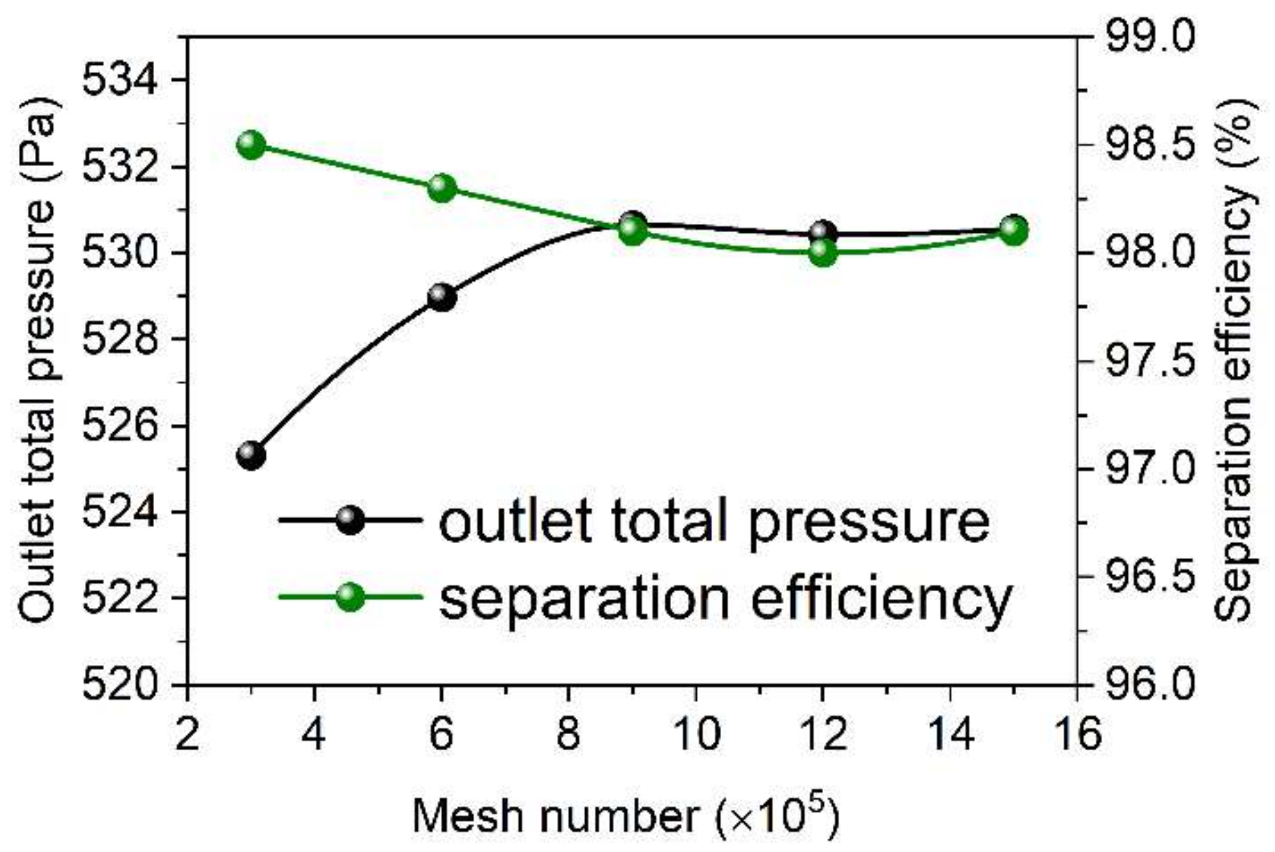
The number of meshes a significant influence on the numerical simulation results. Therefore, mesh-independent analyses were carried out by increasing the mesh number from 3 × 10⁵ to 9 × 10⁵, with an increase of ~3 × 10⁵ meshes for each time. Figure 3 shows the outlet pressure and separation efficiency of the cyclone obtained based on the numerical simulation carried out with various mesh numbers. As shown in Figure 3, the outlet pressure and separation efficiency change significantly with the increase in mesh number from 3 × 10⁵ to 9 × 10⁵, which indicates that the numerical simulation results are sensitive to the mesh number. However, the change in outlet pressure becomes less sensitive along with the increase in mesh number from 9 × 10⁵ to 15 × 105, which is changed from 530.65 Pa to 530.55 Pa. Similarly, the separation efficiency shows a similar change phenomenon with that of the outlet pressure, which shows no change with the increase in mesh number from 9 × 10⁵ to 15 × 105. These results indicate that a mesh number of 9 × 10⁵ is sufficient for the simulation of cyclone separation, which is therefore adopted for subsequent numerical simulation of cyclone separation.

Figure 3.
Mesh independence analysis.
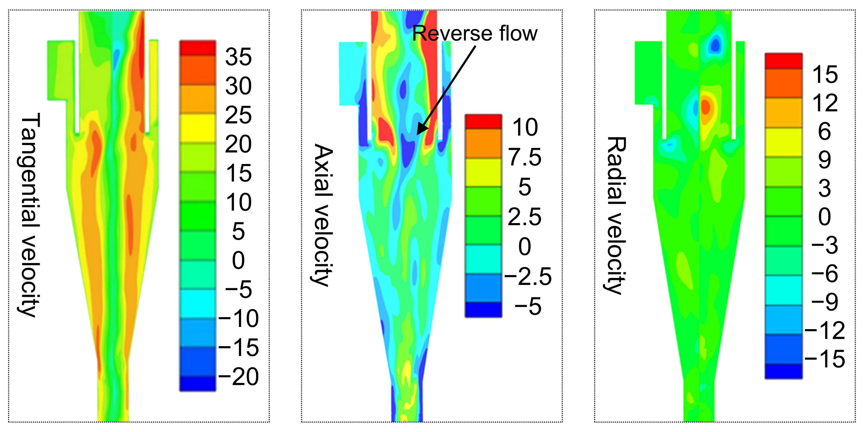
Figure 4 shows the simulation results of velocity distribution in the cyclone, which shows a typical flow pattern of the cyclone, that is, the axial velocity near the wall is always negative, and the positive value is mainly concentrated in the central region. As shown in Figure 4, the tangential velocity component dominates the internal flow field of the cyclone (with the maximum close to 35 m s−1), while the radial velocity component and the axial velocity component are relatively lower than the tangential velocity component. Actually, the radial velocity component is the weakest velocity component, which is in the range from −3 m s−1 to 3 m s−1. However, there is a strong radial flow approaching the upper outlet, which is due to the reverse flow interacting with the outward flow, causing a strong disturbance that further leads to asymmetric flow near the outlet. In the cyclone, the axial velocity distribution determines the up and down flow direction. It is also observed that there is a strong reverse flow (see axial velocity) in the center area of the upper outlet, which generates upward whirlpool flow to keep the flow direction of the intermediate fluid in a different direction.
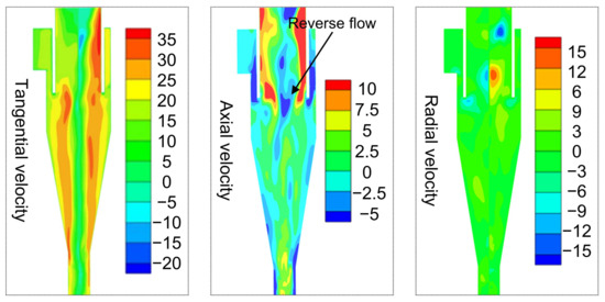
Figure 4.
The distribution of velocity in the cyclone.
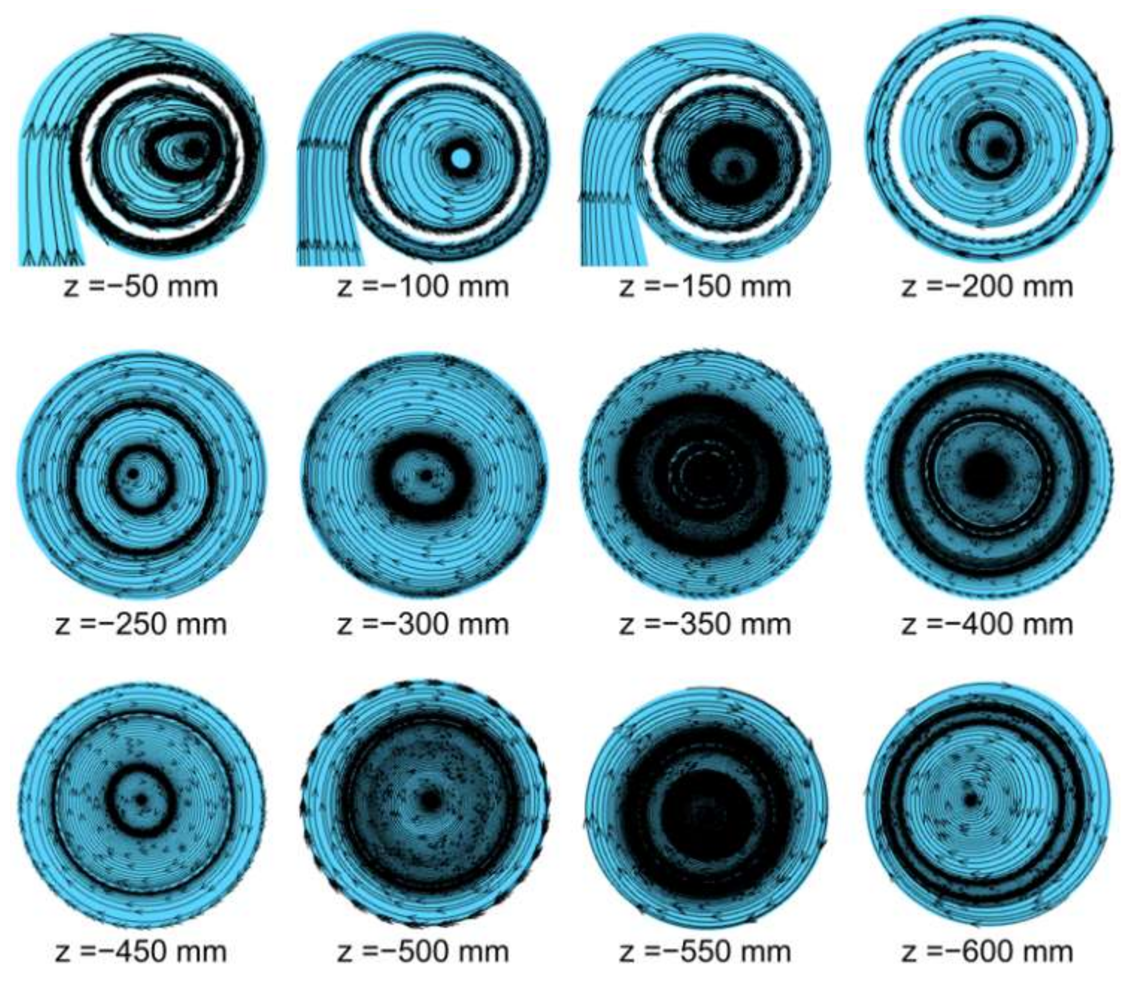
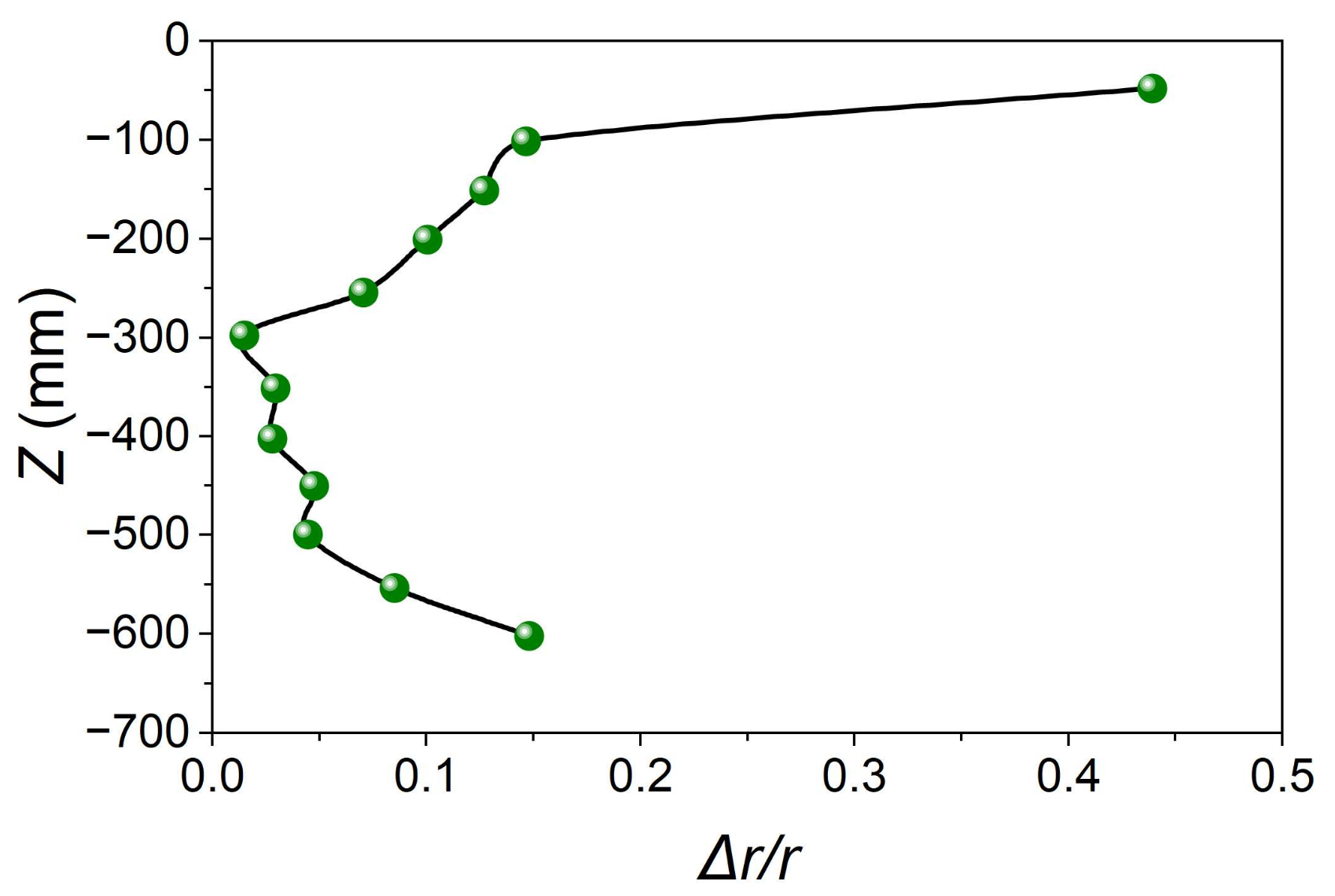
Figure 5 illustrates the streamline distribution of the cyclone in the Z-axis direction, while Figure 6 shows the location of the vortex center (Δr/r), where Δr represents the distance between the vortex center and the geometric center and r represents the local radius (Table A3). The combination of streamline distribution in the Z-axis direction with the location of the vortex center confirms the existence of both symmetric and asymmetric flows inside the cyclone. As shown in Figure 5, the vortex center inside the cyclone is close to the geometric center of the cylindrical part of the cyclone, which was found to deviate from the geometric center at the bottom of the cyclone due to the reverse flow observed at the outlet of the cyclone leading to the formation of perturbation.

Figure 5.
Vortex distribution on each plane.
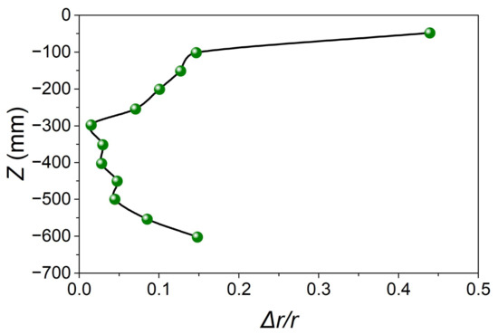
Figure 6.
Deviation distance of the vortex core from the geometric center.
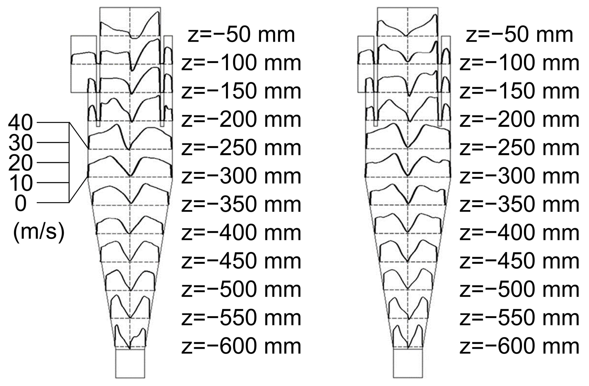
Figure 7 shows the tangential velocity distribution on the planes of the Z-axis direction. A typical Rankine vortex is identified for most of the planes in the Z-axis direction. The external flow pattern is a quasi-free vortex and the internal one is a quasi-forced vortex. The tangential velocity on each plane of the Z-axis direction is defined as follows:
where C is a constant value, n equals 1 for the quasi-free vortex, and it equals −1 for the quasi-forced vortex. Tangential velocity was found to decrease to zero rapidly when the flow closes to the internal surface of cyclone, the non-slip boundary condition of which is adopted. This result also proved that a symmetric flow is formed in the cylindrical and conical parts, while an asymmetric flow is mainly distributed near the outlet of the cyclone.

Figure 7.
The distributions of tangential velocity on each plane in the Z-axis direction.
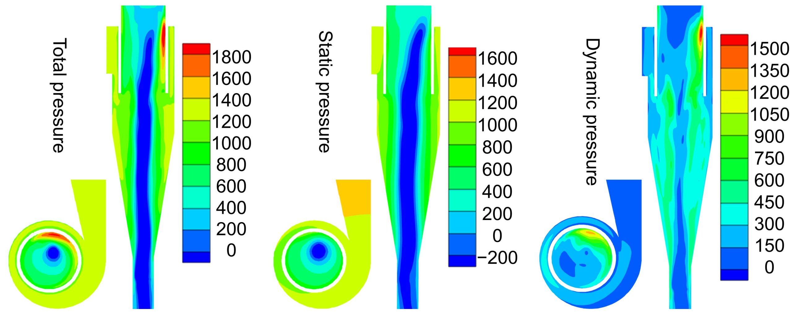
Figure 8 shows the distribution of total, static and dynamic pressures in the cyclone. Theoretically, no energy should be gained after the fluid enters the inlet of cyclone, and the total pressure in the cyclone is considered to decrease along the flow path from the inlet to the outlet due to friction and energy consumption caused by the localized resistance. As shown in Figure 8, the total pressure in the major region of the cyclone obeys the above principles, and only the region near the outlet shows higher total pressure. The decomposition of the total pressure into static and dynamic pressures reveals that the distribution of static pressure and dynamic pressures in the cyclone is generally consistent with the theoretical prediction, while the localized high total pressure is mainly attributed to the increase in the dynamic pressure in this region.
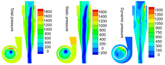
Figure 8.
The distribution of total, static and dynamic pressure in the cyclone model.
We further carried out computational fluid dynamics (CFD) calculations based on the established cyclone model to calculate the pressure drop in the cyclone. Moreover, the pressure drops in the cyclone equipment (Figure 2) utilized for the following separation experiments with oily sludges were also measured. As shown in Figure 9, the CFD calculation results are highly consistent with the measured data on the cyclone equipment, which confirms that the pressure drop rises with the increase in flow rate. There are two reasons for the effects on the flow rate and the pressure drops in the cyclone. The first reason is that the friction loss being is proportional to the square of the velocity (Equation (8)), and that the velocity is proportional to the flow rate. Therefore, the friction loss is considerably larger at a higher flow rate. Another reason is that the turbulence has stronger intensity when the velocity of the inlet flow becomes higher. It can also be noted that the pressure drop predicted by CFD calculations is always lower than that of measured data from the cyclone equipment, which is likely due to that the pressure loss generated by the interactions among particles or between particles and the cyclone, which are not considered in the numerical calculations. Despite the differences, good agreement between the CFD calculations and the measured data from the cyclone equipment validated the reliability of the established cyclone model for numerical simulations.
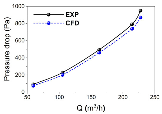
Figure 9.
Comparison of the CFD calculations and the measured data from the cyclone equipment.
As for the cyclone separation, the rotation speed of particles in the cyclone mainly depends on the local tangential velocity (Uθ) and its gradient along radius as follows:
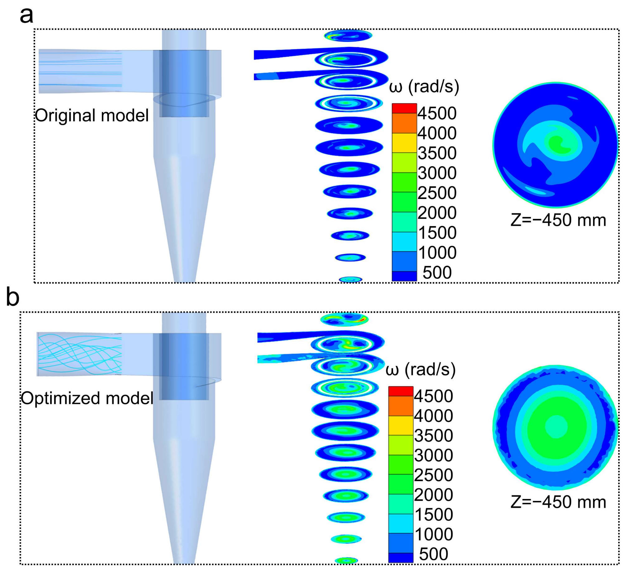
In order to enhance the rotation of particles, we carried out the CFD calculations by tuning the inlet flow pattern of the cyclone from linear flow to vortex flow. As shown in Figure 10, the rotation speed of particles based on the CFD calculations using the vortex flow inlet (the optimized model) shows evident enhancement as compared with those of CFD calculations using the linear flow inlet (the original model), which enlarges the area of the effective rotation zone by up to 400% (the plane at −450 mm in the Z-axis direction) and significantly increases the peak rotational speed close to 4500 rad/s. For the CFD calculations employing the vortex flow inlet, high-velocity rotation was found to be mainly located in the forced vortex flow and the attached surface layer in all planes. This phenomenon is explained by the fact that when the fluid approaches the solid interface, the tangential velocity tends to decrease to zero, while the tangential velocity gradient increases steeply. These results reveal that the rotation-based separation capability of the cyclone can be significantly enhanced by using the vortex flow as the inlet flow, and the purification of the particles mainly occurs in the forced vortex and the boundary layer.

Figure 10.
Comparison of inlet flow pattern and rotation speed distribution: (a) the original model; (b) the optimized model.
3.2. The Separation Results of Oily Sludge by Cyclone
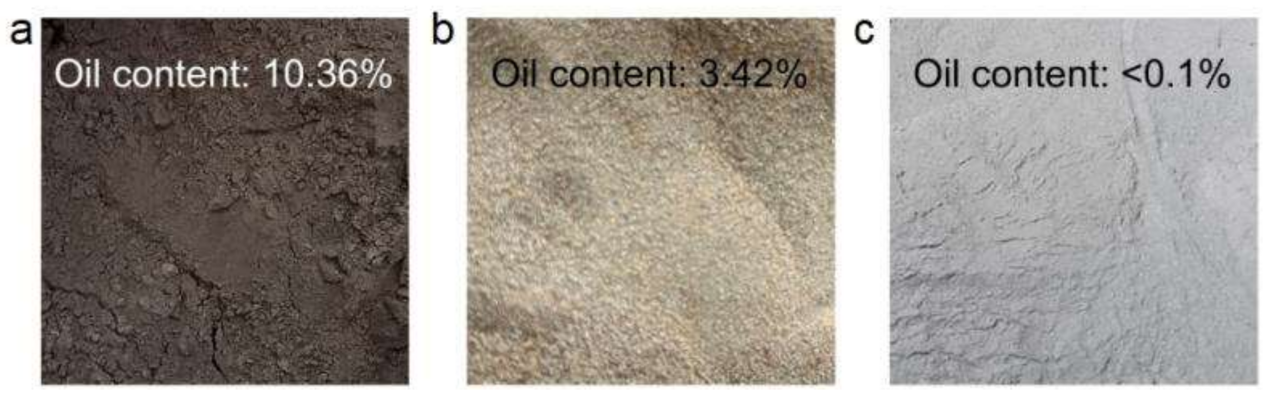
The separation of oily sludges was carried out with the cyclone equipped with a worm shell situated in front of the inlet port of the cyclone, which was capable of generating vortex flow using rotating blades to supply the inlet flow of cyclone. For comparison, the separation of oily sludges was also carried out using the cyclone without collection via worm shell. As shown in Figure 11a, the original oily sludges are dark brown, and the oil content is as high as 10.36%. After the separation by the cyclone without the collection of a worm shell, the already-separated oily sludges (denoted as cyclone-separated oily sludges) show an evidently lighter color, while still providing a high oil content of 3.42%. Notably, the cyclone equipped with a worm shell that generates vortex flow at the inlet successfully reduced the oil content in the separated oily sludges (denoted as optimized cyclone-separated oily sludges) to lower than 0.1% (0.02%), and the separated oily sludges show even lighter color than the cyclone separated-oily sludges. Therefore, these separation results strongly indicate that tuning the inlet flow pattern from linear flow to vortex flow significantly accelerates the rotation speed of oily sludge particles and high-speed rotation areas, which therefore enables the significant improvement of separation efficiency of oily pollutants from the oily sludges.

Figure 11.
Digital images of (a) oily sludges, (b) cyclone-separated oily sludges and (c) optimized cyclone-separated oily sludges.
4. Conclusions
In the present investigation, we developed a promising alternative for the efficient separation of oily pollutants from oil sludges that were generated by the shale gas industry. A series of CFD calculations were systematically carried out to simulate the cyclone separation that employed linear inlet flow and vortex inlet flow, respectively. The CFD calculations confirmed the essential role of the vortex inlet flow for the enhancement of the rotation speed of particles as well as the enlargement of the area of effective rotation zone. Furthermore, a novel piece of cyclone separation equipment was fabricated, which comprised a cyclone and a worm shell collected in front of the inlet port of the cyclone to generate vortex inlet flow with rotating blades. Separation experiments on oily sludges proved that the worm shell effectively generated vortex inlet flow to the cyclone, which indeed improved the separation performances of the cyclone for oily sludges. Our investigations show a new way to design a high-performance cyclone separation technique and also provide an efficient approach for the treatment of oily sludges.
Author Contributions
Conceptualization, B.S.; Methodology, R.Y.; Investigation, R.Y. and W.Z.; Data curation, R.Y. and W.Z.; Writing—original draft, R.Y. and W.Z.; Writing—review & editing, B.S.; Supervision, B.S.; Funding acquisition, B.S. All authors have read and agreed to the published version of the manuscript.
Funding
This research was funded by the Tianfu Yongxing Laboratory Organized Research Project Funding (No. 2024KJGG20) and the Fundamental Research Funds for the Central Universities.
Data Availability Statement
The corresponding author’s data supporting this study’s findings are available upon reasonable request.
Conflicts of Interest
The authors declare no conflict of interest.
Appendix A

Table A1.
The geometrical parameters of the cyclone model.
Table A1.
The geometrical parameters of the cyclone model.
| Geometrical Parameters | Symbol | Value |
|---|---|---|
| Inlet diameter | D1 | D1/D1 = 1.0 |
| Cylinder diameter | D2 | D2/D1 = 1.5 |
| Circular cone bottom diameter | D3 | D3/D1 = 0.5 |
| Outlet diameter | D4 | D4/D1 = 1.0 |
| Length of collector | L1 | L1/D1 = 0.5 |
| Length of circular cone | L2 | L2/D1 = 2.8 |
| Length of cylinder | L3 | L3/D1 = 1.9 |
Table A2.
The detailed parameters of cyclone separation equipment.
Table A2.
The detailed parameters of cyclone separation equipment.
| Instrument | Model | Range | Accuracy | Error |
|---|---|---|---|---|
| Blower | RB-61D-A2 | 0–270 m3 h−1 0–22 kPa | - - | - - |
| Gas flow meter | JY-BS-100 | 0–300 m3 h−1 | 1% | ±3.0 |
| Pressure sensors | GG10-G15 | 0–30 kPa | 0.2% | ±0.06 |
| Temperature sensor | WTZP-EM2B | 0–100 °C | 0.2% | ±0.2 |
Table A3.
The location of the vortex center in the Z-axis direction.
Table A3.
The location of the vortex center in the Z-axis direction.
| Z (mm) | Δr | r | Δr/r |
|---|---|---|---|
| −50 | 23.42008 | 53.5 | 0.437758 |
| −100 | 11.00691 | 75 | 0.146759 |
| −150 | 9.481034 | 75 | 0.126414 |
| −200 | 7.50733 | 75 | 0.100098 |
| −250 | 5.27731 | 75 | 0.070364 |
| −300 | 1.103676 | 75 | 0.014716 |
| −350 | 1.984943 | 67.5 | 0.029407 |
| −400 | 1.581139 | 59.3 | 0.026663 |
| −450 | 2.300011 | 51 | 0.045098 |
| −500 | 1.868154 | 42.8 | 0.043648 |
| −550 | 2.906888 | 34.5 | 0.084258 |
| −600 | 3.88125 | 26.3 | 0.147576 |
References
- Noh, S.; Heo, J.; Woo, S.; Kim, S.; Ock, M.; Kim, Y.; Yook, S. Performance improvement of a cyclone separator using multiple subsidiary cyclones. Powder Technol. 2018, 338, 145–152. [Google Scholar] [CrossRef]
- Misiulia, D.; Andersson, A.G.; Lundström, T.S. Computational Investigation of an Industrial Cyclone Separator with Helical-Roof Inlet. Chem. Eng. Technol. 2015, 38, 1425–1434. [Google Scholar] [CrossRef]
- Wang, Z.; Sun, G.; Jiao, Y. Experimental study of large-scale single and double inlet cyclone separators with two types of vortex finder. Chem. Eng. Process. Process Intensif. 2020, 158, 108188. [Google Scholar] [CrossRef]
- Elsayed, K. Design of a novel gas cyclone vortex finder using the adjoint method. Sep. Purif. Technol. 2015, 142, 274–286. [Google Scholar] [CrossRef]
- Hoffmann, A.C.; de Jonge, R.; Arends, H.; Hanrats, C. Evidence of the ‘natural vortex length’ and its effect on the separation efficiency of gas cyclones. Filtr. Sep. 1995, 32, 799–804. [Google Scholar] [CrossRef]
- Hoffmann, A.C.; Peng, W.; Dries, H.; Regelink, M.; Foo, K.-K. Effect of Pressure Recovery Vanes on the Performance of a Swirl Tube, with Emphasis on the Flow Pattern and Separation Efficiency. Energy Fuels 2006, 20, 1691–1697. [Google Scholar] [CrossRef]
- Gao, Z.; Wang, J.; Liu, Z.; Wei, Y.; Wang, J.; Mao, Y. Effects of different inlet structures on the flow field of cyclone separators. Powder Technol. 2020, 372, 519–531. [Google Scholar] [CrossRef]
- Ma, L.; Shen, Q.; Li, J.; Zhang, Y.; Wu, J.; Wang, H. Efficient gas-liquid cyclone device for recycled hydrogen in a hydrogenation unit. Chem. Eng. Technol. 2014, 37, 1072–1078. [Google Scholar] [CrossRef]
- Wang, L.; Xie, C.; Wang, Z.; Chen, K. Optimization analysis and Field application of gas-liquid cyclone separator based on CFX. Adv. Mech. Eng. 2022, 14, 1–15. [Google Scholar] [CrossRef]
- Wang, Q.; Chen, J.; Wang, C.; Ji, Y.; Shang, C.; Zhang, M.; Shi, Y.; Ding, G. Design and performance study of a two-stage inline gas-liquid cyclone separator with large range of inlet gas volume fraction. J. Pet. Sci. Eng. 2023, 220, 111218. [Google Scholar] [CrossRef]
- Nakhaei, M.; Lu, B.; Tian, Y.; Wang, W.; Dam-Johansen, K.; Wu, H. CFD modeling of gas–solid cyclone separators at ambient and elevated temperatures. Processes 2020, 8, 228. [Google Scholar] [CrossRef]
- Chu, K.W.; Wang, B.; Yu, A.B.; Vince, A. Particle scale modelling of the multiphase flow in a dense medium cyclone: Effect of vortex finder outlet pressure. Miner. Eng. 2012, 31, 46–58. [Google Scholar] [CrossRef]
- Mazyan, W.I.; Ahmadi, A.; Ahmed, H.; Hoorfar, M. Increasing efficiency of natural gas cyclones through addition of tangential chambers. J. Aerosol Sci. 2017, 110, 36–42. [Google Scholar] [CrossRef]
- Ko, M.S.; Chen, Y.L.; Wei, P.S. Recycling of municipal solid waste incinerator fly ash by using hydrocyclone separation. Waste Manag 2013, 33, 615–620. [Google Scholar] [CrossRef]
- Vieira, L.G.M.; Damasceno, J.J.R.; Barrozo, M.A.S. Improvement of hydrocyclone separation performance by incorporating a conical filtering wall. Chem. Eng. Process. Process Intensif. 2010, 49, 460–467. [Google Scholar] [CrossRef]
- Senfter, T.; Neuner, T.; Bachmann, C.; Berger, M.; Mayerl, C.; Kofler, T.; Kraxner, M.; Pillei, M. An Empirical Study on the Upcycling of Glass Bottles into Hydrocyclone Separators. Separations 2024, 11, 230. [Google Scholar] [CrossRef]
- Qian, P.; Ma, J.; Liu, Y.; Yang, X.; Zhang, Y.; Wang, H. Concentration distribution of droplets in a liquid-liquid hydrocyclone and its application. Chem. Eng. Technol. 2016, 39, 953–959. [Google Scholar] [CrossRef]
- Nascimento, M.R.M.; Bicalho, I.C.; Mognon, J.L.; Ataíde, C.H.; Duarte, C.R. Performance of a new geometry of deoiling hydrocyclones: Experiments and numerical simulations. Chem. Eng. Technol. 2013, 36, 98–108. [Google Scholar] [CrossRef]
- Elsayed, K.; Lacor, C. Optimization of the cyclone separator geometry for minimum pressure drop using mathematical models and CFD simulations. Chem. Eng. Sci. 2010, 65, 6048–6058. [Google Scholar] [CrossRef]
- Elsayed, K. Optimization of the cyclone separator geometry for minimum pressure drop using Co-Kriging. Powder Technol. 2015, 269, 409–424. [Google Scholar] [CrossRef]
- Chen, J.; Yang, B.; Jiang, Z.A.; Wang, Y. Effect of external cyclone diameter on performance of a two-stage cyclone separator. ACS Omega 2019, 4, 13603–13616. [Google Scholar] [CrossRef] [PubMed]
- Huang, Y.; Li, J.-P.; Zhang, Y.-H.; Wang, H.-L. High-speed particle rotation for coating oil removal by hydrocyclone. Sep. Purif. Technol. 2017, 177, 263–271. [Google Scholar] [CrossRef]
- Wang, H.; Fu, P.; Li, J.; Huang, Y.; Zhao, Y.; Jiang, L.; Fang, X.; Yang, T.; Huang, Z.; Huang, C. Separation-and-Recovery Technology for Organic Waste Liquid with a High Concentration of Inorganic Particles. Engineering 2018, 4, 406–415. [Google Scholar] [CrossRef]
- Xiong, Z.; Wang, Y.; Gu, X.; Yang, Y.; Shang, J. A Study on the Erosion Mechanism of an Axial Cyclone Separator for Gas Purification. Separations 2022, 9, 409. [Google Scholar] [CrossRef]
- Kang, I.; Seo, W.; Im, S.; Kim, K. Cyclone Shapes for Sand and Microplastic Separation: Efficiency and Reynolds Number Relationships. Separations 2024, 11, 222. [Google Scholar] [CrossRef]
- Hoekstra, A.J.; Derksen, J.J.; Van Den Akker, H.E.A. An experimental and numerical study of turbulent swirling flow in gas cyclones. Chem. Eng. Sci. 1999, 54, 2055–2065. [Google Scholar] [CrossRef]
- Wasilewski, M.; Brar, L.S. Effect of the inlet duct angle on the performance of cyclone separators. Sep. Purif. Technol. 2019, 213, 19–33. [Google Scholar] [CrossRef]
- Wasilewski, M. Analysis of the effects of temperature and the share of solid and gas phases on the process of separation in a cyclone suspension preheater. Sep. Purif. Technol. 2016, 168, 114–123. [Google Scholar] [CrossRef]
- Wasilewski, M.; Duda, J. Multicriteria optimisation of first-stage cyclones in the clinker burning system by means of numerical modelling and experimental research. Powder Technol. 2016, 289, 143–158. [Google Scholar] [CrossRef]
- Morsi, S.A.; Alexander, A.J. An investigation of particle trajectories in two-phase flow systems. J. Fluid Mech. 1972, 55, 193–208. [Google Scholar] [CrossRef]
- Haider, A.; Levenspiel, O. Drag coefficient and terminal velocity of spherical and nonspherical particles. Powder Technol. 1989, 58, 63–70. [Google Scholar] [CrossRef]

Disclaimer/Publisher’s Note: The statements, opinions and data contained in all publications are solely those of the individual author(s) and contributor(s) and not of MDPI and/or the editor(s). MDPI and/or the editor(s) disclaim responsibility for any injury to people or property resulting from any ideas, methods, instructions or products referred to in the content. |
© 2025 by the authors. Licensee MDPI, Basel, Switzerland. This article is an open access article distributed under the terms and conditions of the Creative Commons Attribution (CC BY) license (https://creativecommons.org/licenses/by/4.0/).