Article

Research on the Flow Field Characteristics of the Industrial Elliptical Cyclone Separator

1
Collaborative Innovation Center for Shandong’s Main Corp Production Equipment and Mechanization, Qingdao 266109, China
2
Academy of Agricultural Planning and Engineering, Ministry of Agriculture and Rural Affairs, Beijing 100125, China
3
Key Laboratory of Agro-Products Primary Processing, Ministry of Agriculture and Rural Affairs, Beijing 100125, China
4
Department of Mechanical Engineering, Hebei University of Science and Technology, Shijiazhuang 050018, China
*
Authors to whom correspondence should be addressed.
Separations 2025, 12(2), 50; https://doi.org/10.3390/separations12020050
Submission received: 16 December 2024 / Revised: 23 January 2025 / Accepted: 7 February 2025 / Published: 13 February 2025
(This article belongs to the Section Separation Engineering)

Abstract

:
A new type of elliptical cyclone separator has been proposed recently, but the flow field characteristics within the industrial device still need to be further investigated. In this paper, the characteristics of the flow field and particle motion inside the circular cyclone and the elliptical cyclone (with a long-to-short axis ratio of 1.2), with the equivalent hydraulic diameter of 300 mm, are comparatively analyzed using CFD methods. The results show that there is a significant change in the flow field distribution of the elliptical cyclone compared to the conventional circular cyclone. The static pressure gradient of the elliptical cyclone is anisotropic in the radial direction. The overall tangential velocity value is reduced, which reduces friction loss and makes the pressure drop of the elliptical cyclone significantly lower. More importantly, an acceleration/deceleration phenomenon of the airflow velocity occurs in the elliptical separator along the horizontal circumference, that is, the flow field is transformed into a circumferential fluctuating cyclonic field. This phenomenon induces an additional inertial separation effect that compensates for the unfavorable effects caused by the reduced centrifugal strength. Due to the coupling of centrifugal force and additional inertia effect, the residence time of small particles with a diameter of 1 micron in the elliptical cyclone is shorter, which helps to reduce the backmixing of particles and improves the separation efficiency of the elliptical cyclone. This study reveals the unique flow field characteristics of industrial elliptical cyclones, which is helpful to further understand the particle separation mechanism in the circumferential wave swirl field.

1. Introduction

As a classic high-efficiency gas–solid separation equipment [1], cyclone separators have been used for more than 100 years [2] and are still widely used in mining, the chemical industry, agriculture and other fields [3,4,5]. However, there are harmful flows in its internal flow, such as longitudinal circular flow, short-circuit flow, and eccentric circular flow, which seriously affect the performance of the separator [6,7,8]. Current studies usually consider the structure shape and size as the key factors affecting the flow field of the cyclone [9,10,11]. Therefore, the design of new structures with high efficiency and low resistance characteristics is a popular topic in cyclone separator research. At present, the structural optimization of cyclones can be divided into adding additional structures or adjusting the size and shape of existing structures according to the different structural improvement methods.
Adding additional structures to the cyclone can improve flow field stability or reduce harmful flow. Duan et al. [12] proposed a strategy to optimize the flow structure by installing a cylindrical vortex stabilizer, resulting in a 5.52% improvement in the separation of particles smaller than 3 μm. Gong et al. [13] discovered that the insertion of a rod can lead to a reduction in the pressure drop by 20% without reducing the separation efficiency via enhancing the stability of the flow field. Cao et al. [14] incorporated a deswirler into the vortex finder of the cyclone, effectively enhancing efficiency and reducing the pressure drop by improving the airflow rotation intensity in the vortex finder and reducing the backmixing probability. Feng [15] designed a cyclone with a nozzle, which can improve the separation efficiency for particles with diameters of 1 μm by allowing particles to enter the separation zone earlier. Zheng [16] developed a new cyclone design called the enhanced cyclone with split flow (ECSF), which reduced circulating, short-circuit, and eccentric flows by using bypass and underflows. Although the structural changes improved the cyclone’s performance, its more complex design also led to higher maintenance costs.
Adjusting the shape and size of existing structures are the common methods to improve the performance of cyclones. The structure of the inlet will affect the length of the natural vortex in the cyclone, which means reducing the inlet dimensions will reduce the maximum efficiency height [17] and reducing the inlet dimensions will reduce the pressure drop [18]. The diameter and shape of the vortex finder have also been found to have a significant impact on the performance of the cyclone [19,20]. In general, a reasonable increase in the diameter of the vortex finder can reduce the pressure drop and increase the Stokes number [21,22]. Yuan [23] established that the optimal insertion depth of the vortex finder for maximum efficiency is subject to a decrease as the diameter is reduced and is independent of the inlet velocity at this insertion depth. By studying the characteristic frequency of the dustbin, Zhu [24] believes that the backmixing probability can be effectively reduced when the diameter and height of the dustbin are 1.5 times the diameter of the cylinder. In addition, the cross-sectional shape of the cylinder and cone is considered to have a great influence on the swirl strength [25,26,27].
Sun et al. [28,29,30] developed an efficient elliptical cyclone on the model of Stairmand cyclone separators by using an additional self-activation inertial field method. Through particle separation experiments [28], it was found that the elliptical cyclone with a/b = 1.2 has an efficiency increase of 2.5% and a pressure drop reduction of more than 30% compared to the basic type; the characteristics of circumferential acceleration and deceleration of the swirling eddy were found using CFD simulations to generate inertial forces that enhance centrifugal action and strengthen the separation effect [28,29]. In addition, the wide applicability of the elliptical section structure to various types of cyclones was discussed and a performance prediction model was established [30].
Although the current research on the separation performance and flow field characteristics of small elliptical cyclones (D = 100 mm) has summarized some regularities, the flow field characteristics of industrial cyclones need to be further explored. In this study, CFD simulation work is carried out on industrial conventional and elliptical cyclones to confirm that industrial elliptical cyclones can still maintain the flow field characteristics of tangential velocity in relation to circumferential periodic acceleration and deceleration and has the advantages of high efficiency and low resistance in work performance and to lay the foundation for the industrial application of elliptical cyclones.

2. Models and Methods
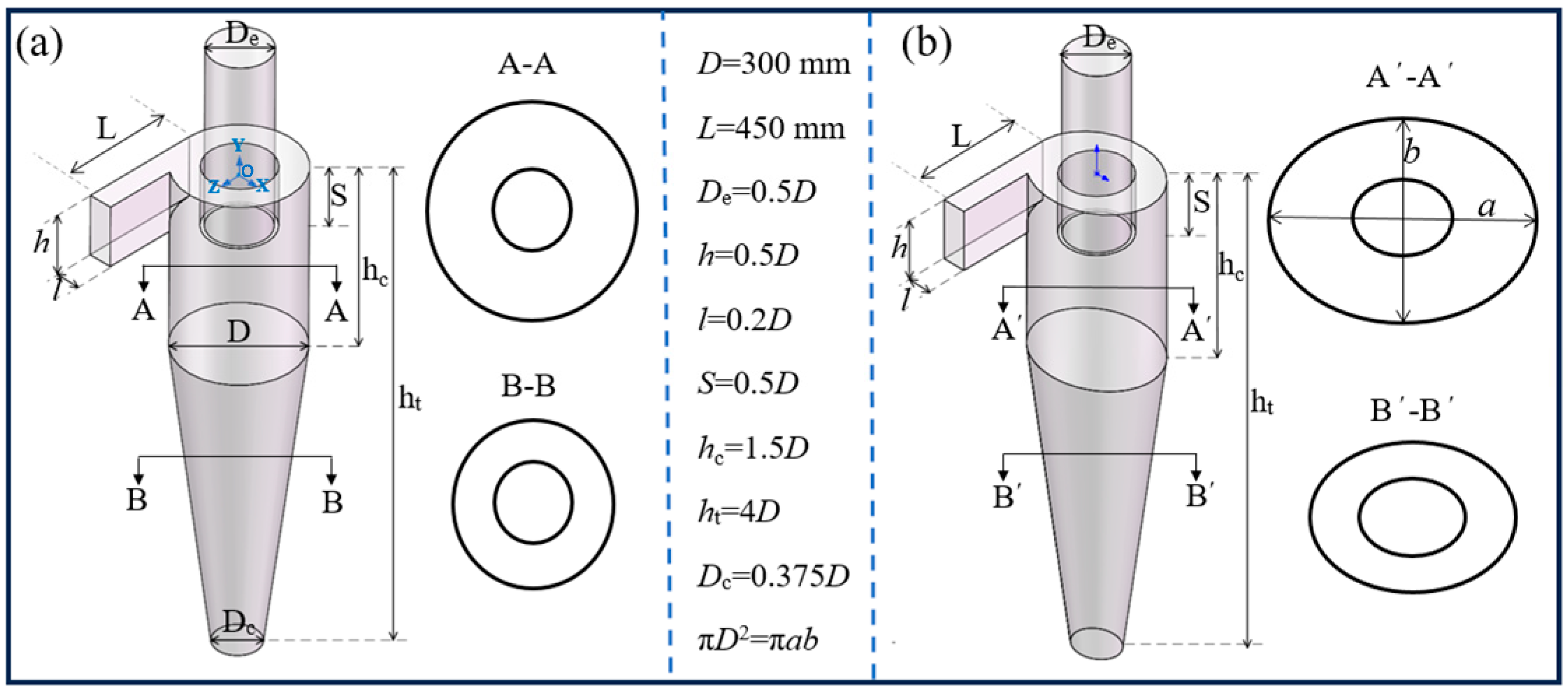
2.1. Cyclone Models

Figure 1 shows the structure of the industrial conventional and elliptical cyclone separators. Moreover, the dimensions of different structures are also listed in Figure 1. In the figure, the center O at the top of the cylinder of the circular separator is the origin of the x y z coordinate axis. For the circular separator, D is the diameter of the cylinder, and each structural size of the separator is related to D. For the elliptical separator equivalent diameter D e q = D = a b , other sizes are the same as the original. To ensure that the two cyclones have the same Reynolds number and cross-section air flux at the same inlet velocity, models with the same dimensions for the inlet and vortex finder were designed, and the hydraulic diameters were always 300 mm.

2.2. Numerical Methods

2.2.1. Turbulence Model

Many studies have confirmed the reliability of the Reynolds stress model (RSM) and large eddy simulation (LES) for turbulence modeling [31,32,33]. To reduce computational cost and time, the RSM was chosen as the appropriate model for this work. For an incompressible flow in the cyclones, the mass and momentum equations can be expressed as follows:
v i x i = 0
ρ ν i t + ρ ν i v j v j = p x i + x j μ ν i x i + v j x j ρ v i v j ¯ x i
Let xi and x j   represent the position in meters (m), t denote time in seconds (s), ρ be the constant gas density in kilograms per cubic meter (kg/m3), p represent the mean static pressure in Pascals (Pa), and μ be the gas viscosity in (kg/(m·s)). ν i and v j represent the fluid velocity components, and the speed unit is meters per second(m/s).
The Reynolds stress model of turbulence is described by the following equation:
t ρ v i v j ¯ + x k ( ρ v i v j ¯ v k ) = D i j + p i j + ϕ i j ε i j
ρ : density of the fluid. v: velocity component of a fluid.
D i j : diffusion term, usually associated with viscous diffusion, indicating the diffusion effect of turbulence.
p i j : The pressure term represents the turbulent pressure of the fluid.
ϕ i j : Source term, which may indicate the influence of a heat source, material source, or other external source term.
ε i j : Turbulent dissipation term, representing the energy dissipation of turbulence.
The two terms on the left-hand side of Equation (3) represent the local time derivative and the convection, respectively. On the right-hand side, the four terms correspond to the stress diffusion, stress production, pressure–strain, and dissipation terms, with
D i j = x k μ t σ k v i v j ¯ x k ,   p i j = v i v k ¯ v j x k + v j v k ¯ v i x k
ϕ i j = 1.8 ε k v i v j ¯ 2 3 δ i j k 0.60 p i j 1 3 δ i j p k k ,   ε i j = 2 3 ε δ i j   
where μ t is the viscosity of turbulent flow, k = ( 1 / 2 ) v i v j ¯ is the fluctuation kinetic energy, and ε is the turbulence dissipation rate. σ k : Turbulent Prandtl number, a constant in turbulence models that represents the ratio between energy and momentum transport σ k = 1.82 [34].
The transport equation for the turbulence dissipation rate ε is given by
ε t + ε v i x i = x j μ + μ t σ ε ε x j C ε 1 ε k p i j v i x j C ε 2 ε 2 k
ε : Turbulent dissipation rate, which represents the rate at which turbulent energy is converted into heat.
v: The velocity component of the fluid
μ : Dynamic viscosity of fluid.
μ t : Turbulent viscosity, which represents the effective viscosity of turbulence.
σ ε : Turbulent Prandtl number, used to express the ratio between momentum and energy transfer in turbulence.
p i j : Pressure term, indicating the influence of pressure in turbulence.
C: Constant, used for different terms in the turbulent dissipation equation, usually derived experimentally or theoretically.
k: Turbulent kinetic energy, which represents the energy of turbulent flow.
The values of the constants are σ ε = 1.3, C ε 1 = 1.44, and C ε 2 = 1.92.

2.2.2. Numerical Schemes

The simulations were performed using a segregated pressure-based solver. The PISO algorithm was applied to couple the velocity and pressure terms. For the discretization of the momentum term, the PRESTO interpolation method was selected. The QUICK scheme was used for the momentum equations, while the second-order upwind scheme was adopted for other spatial discretization factors. The calculations were iterated until the root mean square residual was reduced to below 10−5.

2.2.3. Boundary Conditions

The simulation was conducted using room temperature air, treated as an incompressible fluid to simplify the calculations. The inlet and outlet boundary conditions were specified as velocity inlet and free flow, respectively. (Velocity inlet: The inlet flow is specified with a given velocity profile for air entering the cyclone. Free flow: The outlet is considered as an open boundary where air exits without a fixed pressure or velocity profile. Fluid: Air treated as incompressible fluid at room temperature). Pressure–velocity coupling was performed using the SIMPLE algorithm, and the Reynolds stress term was discretized using a second-order upwind scheme. Specific letter symbols are indicated at the end of the article. The hydraulic diameter and turbulent intensity at the inlet were determined using Equation (7) and Equation (8), respectively.
D H = 2 h l h + l
I T = 0.16 ρ g D H ν i n μ 0.125
where ρ g is the density of fluid, kg/m3; D H is the hydraulic diameter of inlet, m; ν i n is the velocity of inlet, m/s; and μ is the viscosity coefficient of fluid, (kg/(m·s).

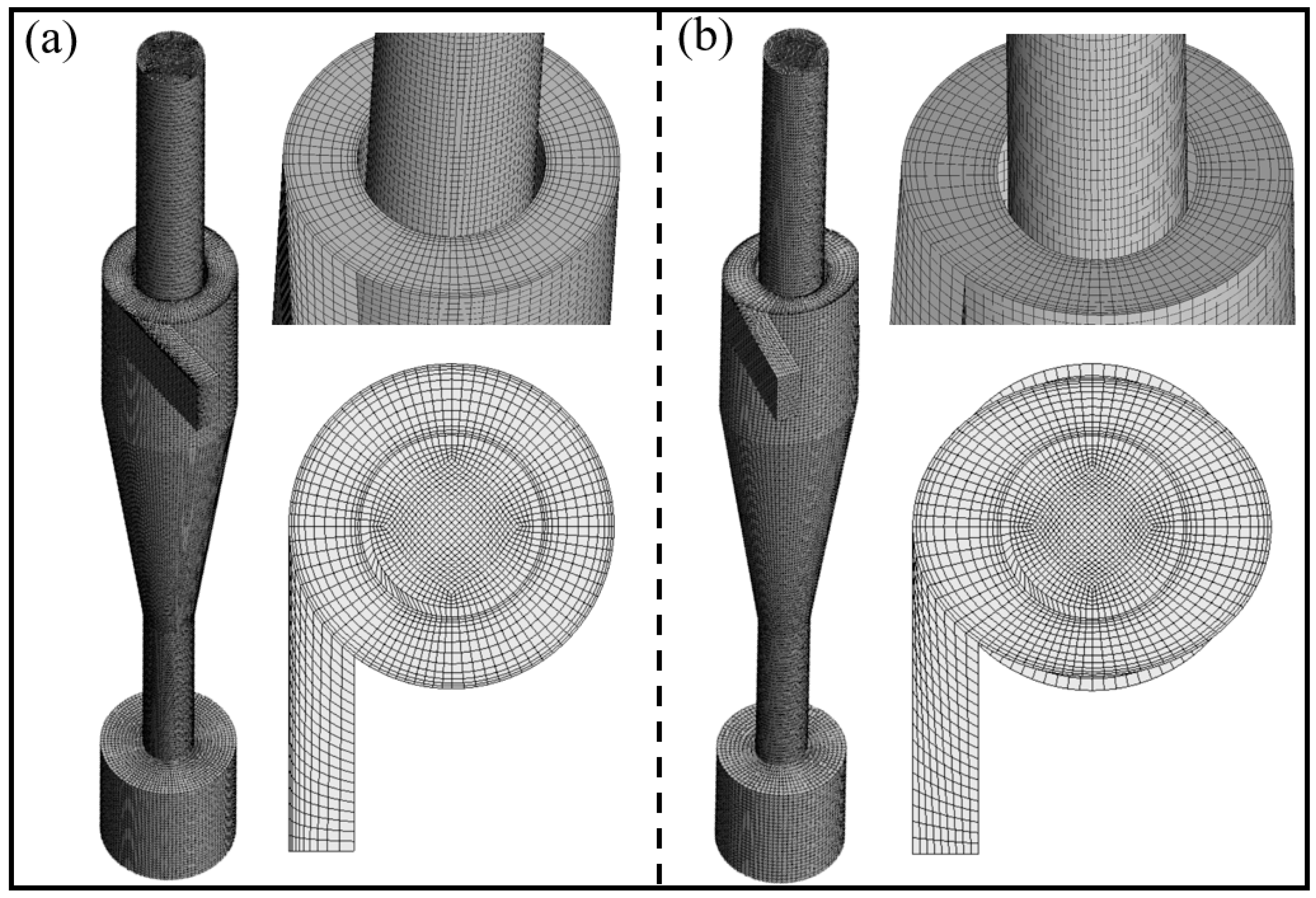
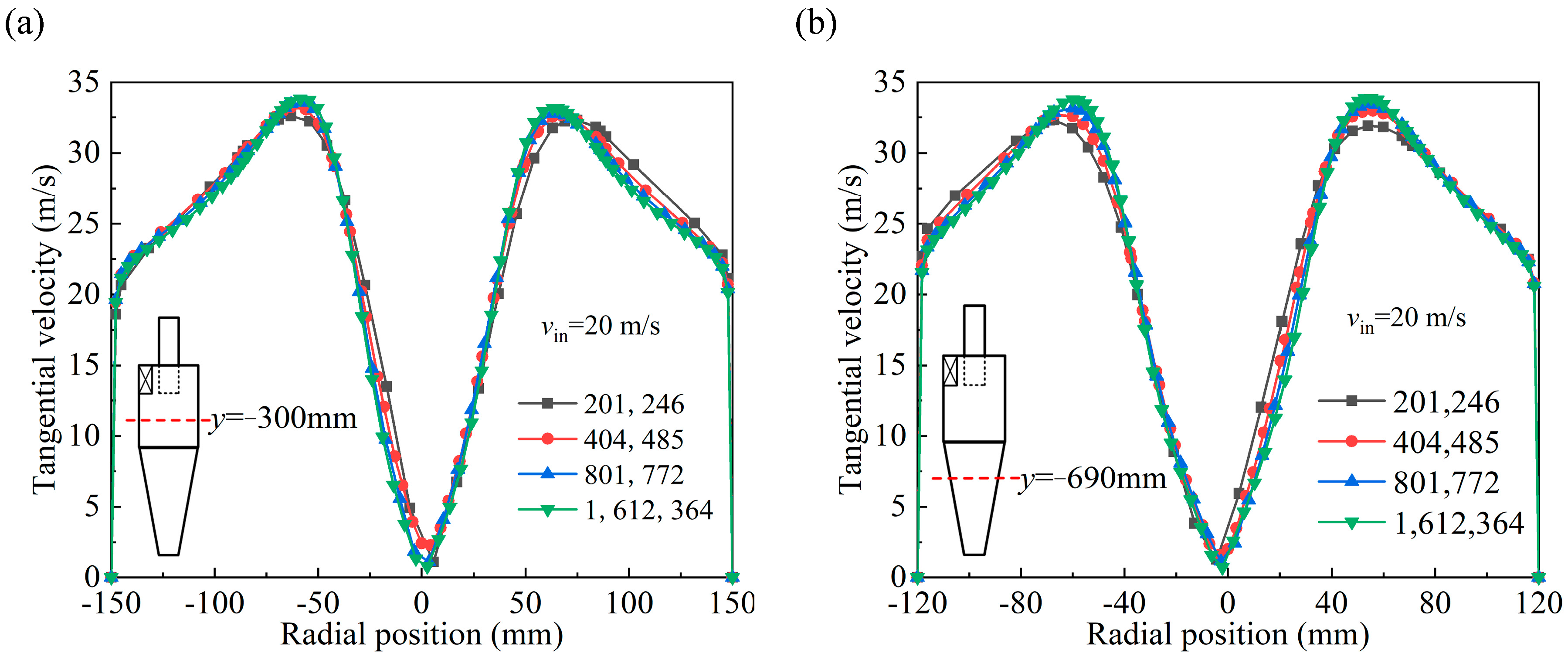
2.3. Grid Division and Independence

The meshing method is very important for the computational accuracy of numerical simulation, ICEM software is used to draw a non-orthogonal hexahedral mesh, which can be well adapted to circular or elliptical walls. This work is refined in the core region and near the wall, which can accurately capture the fluid flow, as shown in Figure 2a,b. The Reynolds number is high in the cyclone, and the value of y+ can reach 30~300 in this research. The maximum y+ values are mainly found in the top and inlet walls of the cylinder.
Figure 3 shows the grid sensitivity study. The tangential velocity reaches stabilization with a floating error of less than 1.5% when the grid count exceeds 801,772 (Figure 3a,b). Consequently, 801,772 grids were selected for the numerical simulations, as they provided consistent results.
At present, for gas–solid two-phase numerical simulation, the Euler–Lagrange method, also known as the Discrete Phase Model (DPM), is usually adopted. The DPM does not consider the interaction between particles by volume, so it requires a solid particle concentration of less than 10%.
At present, the concentration of solid particles in the experiment is relatively low, so this paper will use the discrete particle model to analyze the motion state of solid particles, consider the two-way coupling between the discrete phase and the gas phase, and select the inlet cross section as the particle injection source. The particles are ejected into the cyclone in the direction normal to the inlet cross section, and the initial velocity of the particles is equal to the inlet velocity, which is 20 m/s [35]. The integration step size is set to 0.001 m, the maximum number of particle tracking times is set to 5,000,000, the particle phase is renewed once for each iteration of 40 times in the gas phase, and the particles are regarded as caught once they touch the bottom of the hopper, which can be terminated by the computation. The particle grading material is calcium carbonate, which has a density of about 2700 kg/m3, because the particle density is much larger than the air density, so the influence of Saffman force, Basset force, and virtual mass force on the particles can be completely ignored.
Trap condition. Equations for the discrete particle:
d u p d t = F D v u p p ρ p + g
u p : The velocity vector of the particle, indicating the velocity of the particle in the fluid.
F D : Drag force coefficient, indicating the resistance of the fluid to the particles.
ν : Velocity vector of a fluid, representing the state of motion of the fluid.
p: The pressure gradient of a fluid, representing the change in pressure in the fluid.
ρ P : Density of particles.
g : Gravitational acceleration vector, representing the action of gravity.
F D = 18 μ C D R e p ρ p d p 2 24
where F D is the drag coefficient, given by
Re p = ρ d p u p v μ
where u p is the particle velocity and v is the gas velocity, both m/s. R e p   is the relative Reynolds number. dp is the particle diameter, m.
The drag coefficient is given as,
C D = a 1 + a 2 R e + a 3 R e 2
where a 1 , a 2 , and a 3 are constant coefficients for spherical particles.
In order to take into account the effect of turbulent diffusion, the Discrete Random Walk (DRW) model was applied. The timescale constant was set to 0.15. The fluctuating gas u   velocity is computed as follows:
u = ζ u 2 ¯
Here, ζ represents a normally distributed random number.
Since the kinetic energy k is known at each point in the flow, the values of the fluctuating components of the Reynolds stress model (RSM) can be determined as follows:
u 2 ¯ = v 2 ¯ = w 2 ¯ = 2 k / 3

3. Results and Discussion

3.1. Static Pressure Distribution

There exists a remarkable disparity in the static pressure distribution between the two industrial-grade separators, as depicted in Figure 4. The static isobar graph presents this difference more distinctly. The static pressure distribution of conventional cyclones is center-symmetric, the isobar is similar to a circle and the radial pressure gradient is basically the same, as shown in Figure 5a. However, the static pressure distribution of the elliptical cyclone is no longer isotropic, the static pressure distribution is symmetric about the long axis of the ellipse, the central vortex core is significantly diverging from the geometric center, from the center to the outside, and the isostatic isopiestic gradually changes from circular to elliptical, as shown in Figure 5a, which is consistent with the flow field characteristics of the small elliptical cyclone [28,29]. The above shows that the elliptical shell significantly affects the flow field distribution in the circumferential direction inside the cyclone separator.

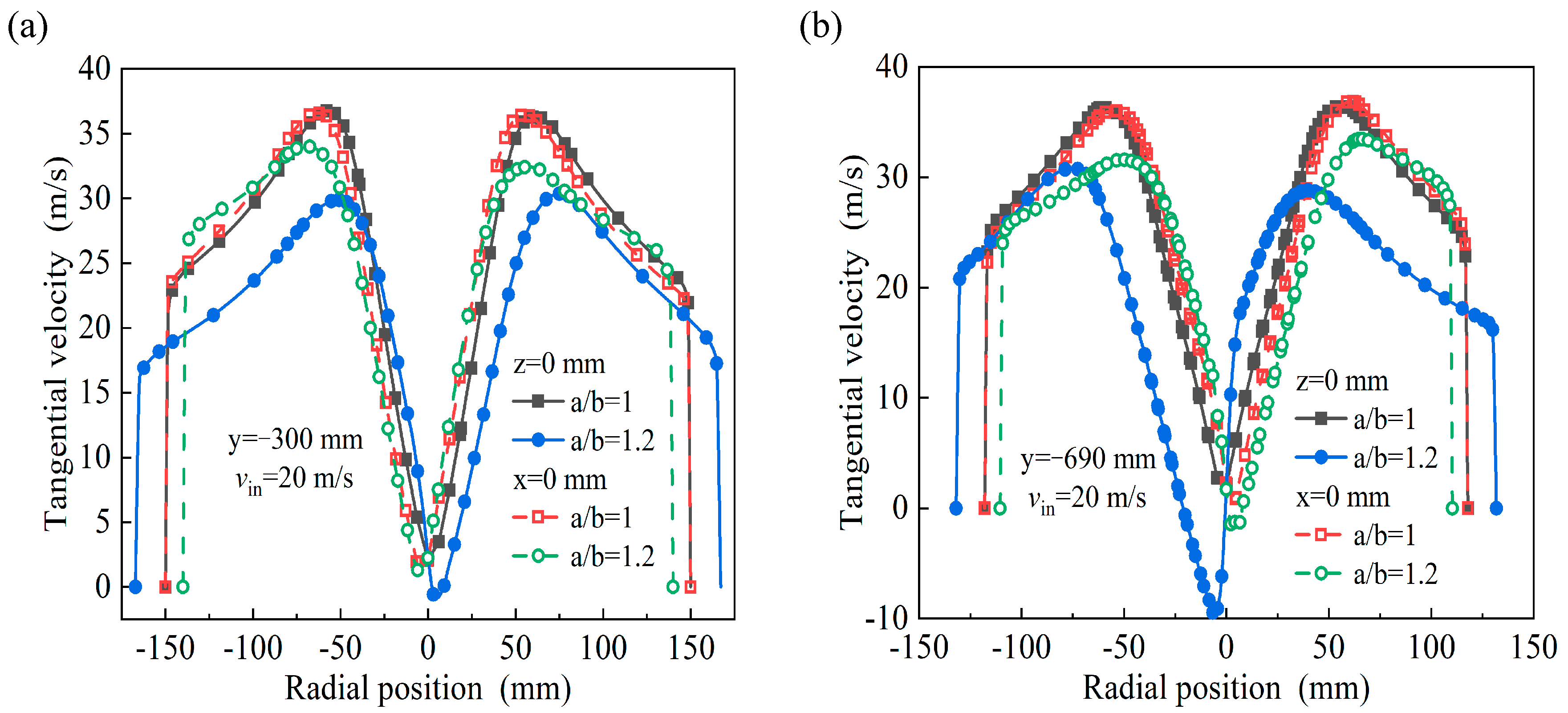
3.2. Velocity Distribution

Figure 6 shows the tangential velocity and axial velocity distribution of the longitudinal section of the industrial separator. As can be seen from the figure, the velocity distribution patterns of the two industrial cyclones are generally consistent with each other, the tangential velocity first increases and then decreases from the wall to center, while the maximum tangential velocity is in the vortex finder downward extension plane. However, the maximum tangential velocity position of the elliptical separator oscillates along the axis. Particularly in the vicinity of the discharge opening, the velocity distribution is even more non-uniform under the influence of the highly unstable vortex core wake.
From the axial velocity distribution, it can be seen that the two industrial cyclone separators have a predominantly downstream flow in the outward area and an upstream flow in the inward area, and the maximum axial velocity occurring at the bottom of the vortex finder is due to the effect of the protruding structure. The positive and negative axial velocities are constantly alternating at the position of dipleg, and there is an obvious phenomenon of secondary flow at this position, which is also the reason why the separated particles have been elutriated twice; this phenomenon has a negative impact on the separation efficiency.
The tangential velocities at different orientations (z = 0 mm and x = 0 mm) of the cylinder and cone cross-sectional positions were quantitatively analyzed, as shown in Figure 7. For the conventional circular separator, the tangential velocity curves for different locations within a given cross section basically overlap, and the maximum tangential velocity value is also larger. However, for the elliptical separator, the tangential velocity values are reduced, the tangential velocity curves in different directions deviate significantly and the maximum tangential velocity values are not consistent. It is shown that the elliptical shell increases the resistance to the conversion of the pressure potential energy of the flow into kinetic energy, resulting in a small decrease in centrifugal strength at the same inlet velocities. It should be noted that the elliptical shell induces alternating acceleration/deceleration of the rotating airflow at the same time, as shown in Figure 8, which confers additional inertial separation of the particles and facilitates enhanced particle separation.
In addition, the tangential velocity at the center of the elliptical cyclone separator barrel and cone showed negative values up to −10 m/s, indicating that the size enlargement resulted in a more complex internal cyclonic flow with localized secondary flows compared to the small-size separator [28,29].
Figure 9 shows the axial velocity distribution of the industrial cyclone. From the figure, it can be seen that, compared with the tangential velocity, the symmetry of the axial velocity distribution becomes worse. However, in general, the axial velocities of the two types of cyclones have the same distribution characteristics, the boundary wall area is negative, most of the internal area is positive, and in the center is the the existence of a “V”-type low velocity zone or even a stagnant area. In contrast, the conventional circular cyclone has a low upstream velocity, the axial velocities in the center area are all negative, and the axial motion of the internal swirl is complicated, which adversely affects the stability of the flow field.
Figure 10 shows the radial velocity distribution of the industrial cyclone separators. From the figure, it can be seen that the radial velocity at most of the positions of the cyclone points to the center and the airflow gradually converges to the center during the rotation. The larger radial velocity of the elliptical cyclone indicates that the stream is transformed into an upstream internal swirl more quickly, which will shorten the time for the airflow to carry particles, reduce the probability of particle entrainment at the cone, and have a positive impact on gas–solid separation.

3.3. Particle Trajectory

The trajectories of particles with diameters of 1 μm, 3 μm, and 5 μm are given in Figure 11. From the figure, it can be seen that for the separator with a/b = 1, the particles move to the middle of the legs, then fold back and move upwards to the cylinder, and then fold back and move downwards again, and there is a significant increase in the number of trajectory lines at the cone, indicating that the particles move repeatedly at the cone and finally move downward to the dustbin to be captured. For the cyclone with a/b = 1.2, the particles enter from the center of the inlet and then rotate downward with the airflow; their trajectory is more chaotic at the cylinder and cone but still helical, and they are eventually captured by the dustbin. By analyzing the trajectory of 3 μm particles, it can be seen that the trajectories of the particles in the two cyclones are more consistent, both are rotating along the wall down to the dustbin. When the particle diameter increases to 5 μm, the particle trajectory is similar to that of a 3 μm particle; the particle trajectory is more regular, the number of particle rotations is reduced, and it is more easily captured by the dustbin.
The inlet air velocity has an important effect on the flow field and particle motion [36,37,38]. The trajectories of small particles at different inlet velocities are given in Figure 12. Under the condition of low inlet velocity (10 m/s), small particles rotate downward under the multiple effects of centrifugal force, airflow traction, and turbulent diffusion after entering the conventional circular cyclone. The particles in the dustbin are obviously affected by turbulence; they will re-enter the circular cyclone under the entrainment of the tail vortex, then be re-separated when it moves upward to a certain position in the cone, and, finally, be captured at the bottom of the dustbin after a complex movement. For the elliptical cyclone, small particles enter the internal swirl at the cone and rotate upward to escape from the vortex finder. This indicates that both the centrifugal strength and the additional inertial effect in the elliptical cyclone are weak at low gas velocities and that there is insufficient trapping capacity for small particles.
As the inlet velocity increases, the centrifugal intensity inside the elliptical cyclone becomes larger and the inertial separation effect induced by the circumferential acceleration/deceleration motion is enhanced. Small particles are difficult to entrain into the internal swirl, and small particles are transported by the outer downstream flow to the dustbin for collection. This means that at higher inlet gas velocities, the additional inertia characteristic of elliptical cyclones will enhance small particle separation and improve overall cyclone performance.

3.4. Comparison of Particle Residence Time

Figure 13a compares the residence times of particles with different particle sizes. For particles with a diameter of 1 μm, the residence time of the particles in the elliptical cyclone is reduced by 30% by centrifugal and inertial separation. However, larger particles with diameters of 3 μm and 5 μm are sufficiently separated by centrifugation, and there was no significant difference in particle residence time.
Figure 13b gives the variation in the residence time of small particles with diameters of 1 μm at different inlet gas velocities. From the figure, the particle residence time of the two types of particles shows the opposite rule to the change in inlet velocity. For the conventional circular cyclone with a single centrifugal force field, the centrifugal force and downstream flow velocity will increase significantly as the inlet velocity increases, so the time for particles to be transported to the dustbin is shortened. However, for the elliptical separator, the particle residence time varies significantly, which may be a combined result of the simultaneous enhancement of centrifugal, inertial, and turbulent diffusion effects.
In the simulation results, it is observed that the residence time increases abnormally with the increase in inlet velocity under the elliptic condition. This phenomenon may be caused by changes in the flow characteristics of the fluid in the channel. In an elliptical channel, the fluid may be affected by the geometry, resulting in a backflow or retention effect, resulting in a longer residence time for the fluid in some areas.

3.5. Comparison of Pressure Drop and Separation Efficiency

Based on the description of Figure 14, the simulation results indicate that the industrial elliptical cyclone separator achieves a lower pressure drop and higher separation efficiency. When the inlet velocity is between 10 and 25 m/s, the pressure drop of industrial elliptical cyclone decreases by 200~300 Pa compared with the traditional cyclone, and the maximum drop reaches 50%. Moreover, the classification efficiency of the industrial grade elliptical cyclone separator is greatly improved compared with the traditional separator, especially for the small particles of 1 μm; the classification efficiency is improved by more than 150%.
In addition, when comparing the experimental results, the simulation experiment error is basically controlled within 10% and the simulation value is numerically higher than the actual value, considering that the error stems from the fact that the actual separation performance is also limited by parameters such as temperature, air humidity, and operational stability, so the ideal fraction efficiency cannot be achieved. The accuracy of the simulation results is acceptable. Specific experimental Settings and the use of equipment are given in the Supplementary Materials.

4. Conclusions

(1)
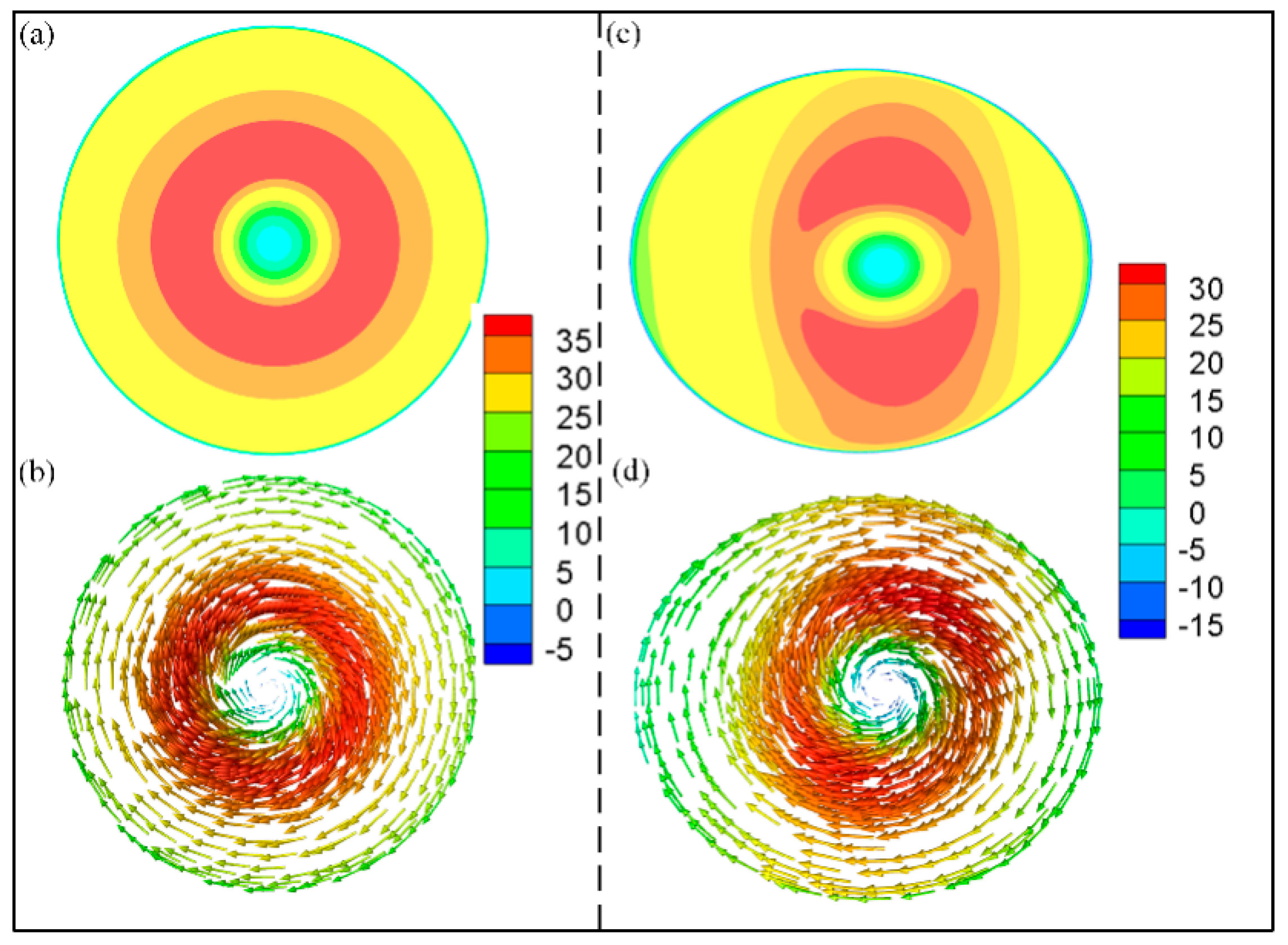
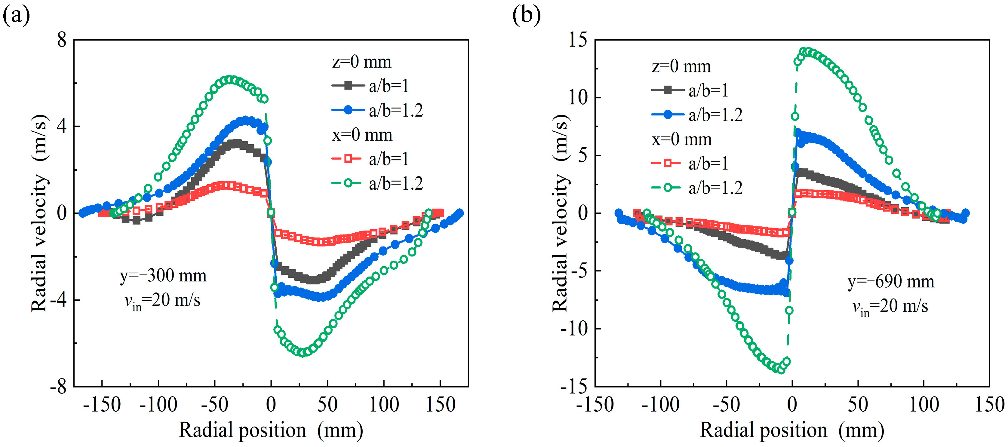
Due to the influence of the structure, the length of the natural cyclone in the elliptical cyclone is shortened, the tangential velocity is reduced, the flow field intensity is reduced, and the corresponding pressure loss of the elliptical cyclone is also reduced. In addition, the pressure and tangential velocity distributions within the cross section of the elliptical cyclone show significant anisotropy and the swirling eddy continuously experiences circumferential acceleration and deceleration processes, producing additional inertial separation effects.
(2)
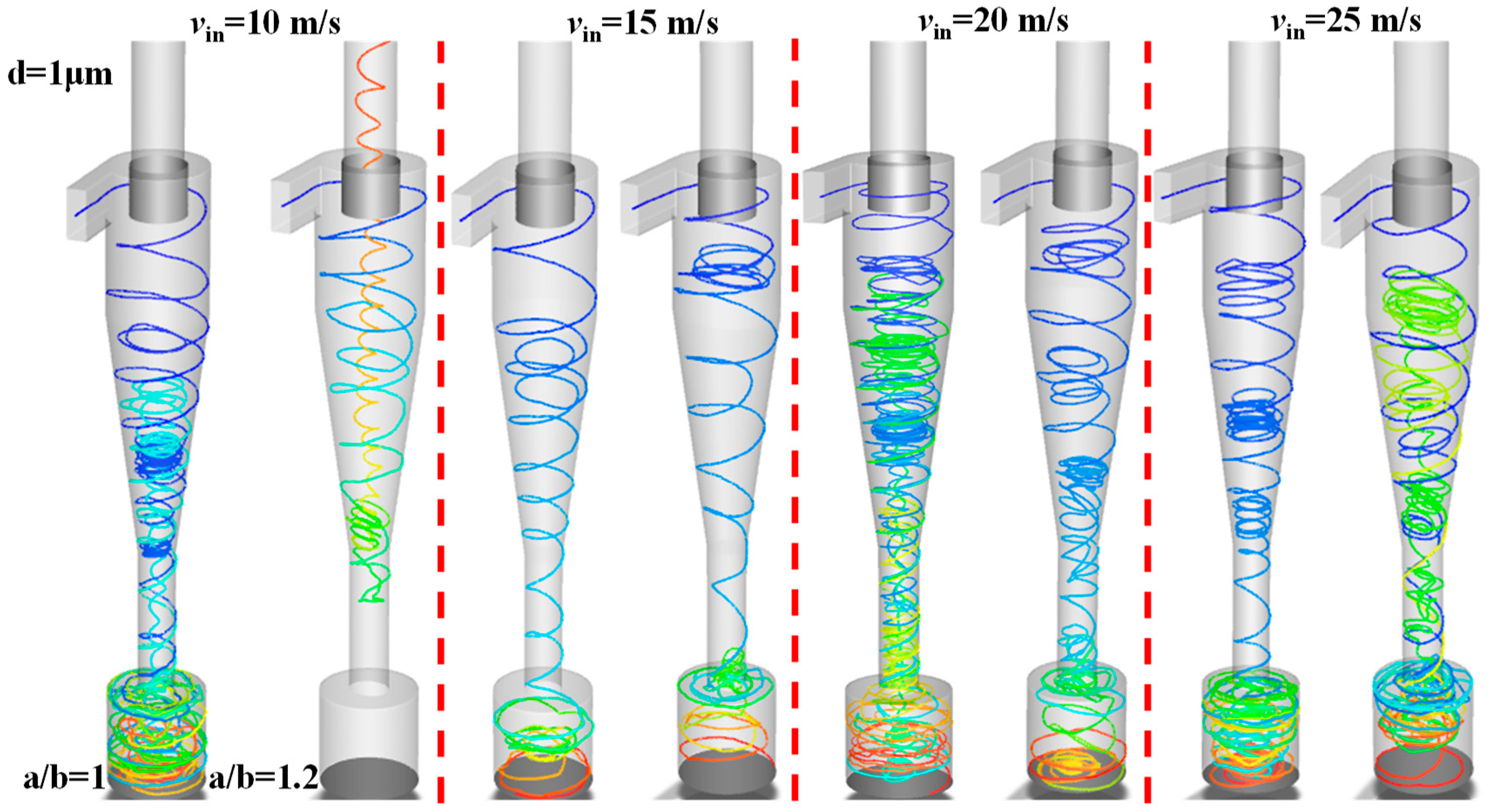
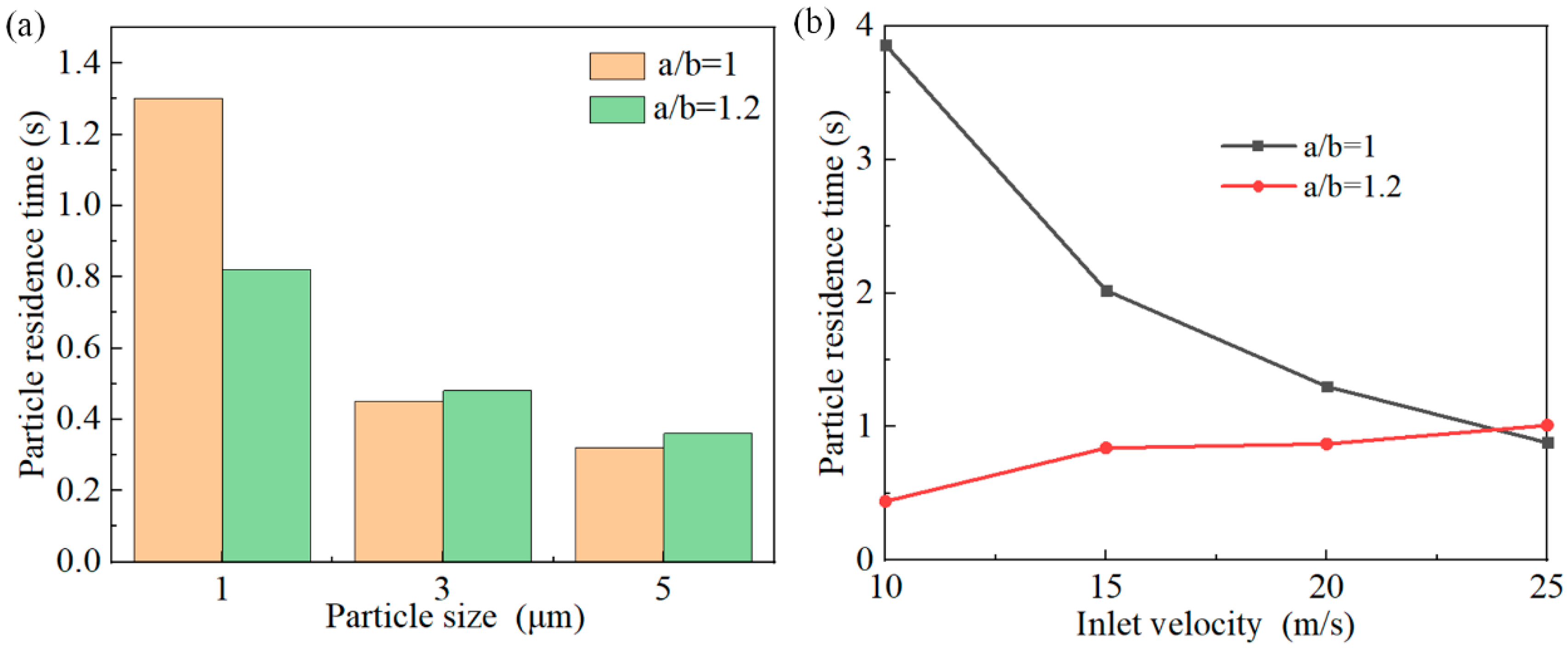
When the particle diameter is 1 μm, the particles in the circular cyclone are affected by the internal and external swirl together, the movement trajectory is complex, and the particle residence time is longer. As for the elliptical cyclone separator, under the effect of centrifugal force and additional inertia, the particles are thrown to the wall and brought into the dustbin by the downward flow; this process has a short particle residence time and a high separation efficiency. With the increase in particle size, the centrifugal force on the particles increases significantly, the particle trajectory is more and more regular, and the particles are quickly separated into the dustbin.
(3)
Inlet velocity affects the additional inertial effect of the elliptical cyclone. At low air velocities (10 m/s), the centrifugal force field in the elliptical cyclone is weak, the additional inertia effect generated by the accelerating/decelerating airflow is weak, the possibility of small particles escaping is increased, and the separation efficiency of the elliptical cyclone is low. However, with an increase in inlet velocity, the additional inertia effect is enhanced and the elliptical cyclone has a higher separator efficiency.
(4)
The simulation results demonstrate that the industrial elliptical cyclone separator (with a/b = 1.2 and D = 300 mm) exhibits higher separation efficiency and a lower pressure drop compared to the conventional cyclone. The combination of simulation and experimental results can strongly prove that the elliptical cyclones have performance advantages and broad application prospects.

Supplementary Materials

The following supporting information can be downloaded at: https://www.mdpi.com/article/10.3390/separations12020050/s1, Figure S1: Large separator physical picture; Figure S2: Device setup; Figure S3: Industrial grade separator performance comparison: (a) pressure drop (b) classification efficiency.

Author Contributions

Conceptualization, K.L.; Methodology, K.L.; Validation, K.Z., G.Z., Z.S. and J.S.; Formal analysis, K.Z.; Investigation, Z.S.; Resources, Y.Z. and Z.S.; Data curation, K.L.; Writing—original draft, K.L., K.Z. and Z.S.; Project administration, Y.Z. All authors have read and agreed to the published version of the manuscript.

Funding

The research was conducted by the Collaborative Innovation Center for Shandong’s Main Corp Production Equipment and Mechanization (SDXTZX-04). Supported by the Independent Research and Development Project of Agricultural Planning and Engineering Institute of the Ministry of Agriculture and Rural Affairs (QD202108), Hebei Central and Local Science and Technology Development Fund Guidance Project (236Z1101G).

Data Availability Statement

Data is not provided here due to privacy.

Acknowledgments

Thanks to Shandong Provincial Enterprise Production Equipment and Mechanization Collaborative Innovation Center, Agricultural Planning and Engineering Institute of the Ministry of Agriculture and Rural Areas and Hebei Provincial Central and local Science and Technology Development Project Fund guidance and funding.

Conflicts of Interest

The authors declare no conflict of interest.

Nomenclature

xnposition (m)ε turbulent dissipation rate ( m 2 / s 3 )
ttime (s) μ t turbulent viscosity (kg/(m·s)
ρgas density (kg/m3) σ ε turbulent Prandtl number
pmean static pressure in Pascals (Pa)Cconstant, used for different terms in the turbulent dissipation equation
μgas viscosity in (kg/(m·s)kturbulent kinetic energy ( m 2 / s 2 )
ν n fluid velocity components, the speed unit is meter per second (m/s). u p the velocity vector of the particle, indicating the velocity of the particle in the fluid (m/s)
D i j diffusion term F D :drag force coefficient, indicating the resistance of the fluid to the particles
p i j the pressure term represents the turbulent pressure of the fluid.∇pthe pressure gradient of a fluid ( P a / m )
ϕ i j source term g gravitational acceleration vector
ε i j turbulent dissipation term, representing the energy dissipation of turbulenceζrepresents a normally distributed random number

References

  1. Guo, M.; Lu, Y.; Xue, C.; Sun, X.; Yoon, J.Y. The impact of cylinder vortex stabilizer on fluctuating turbulence characteristics of a cyclone separator based on Large Eddy Simulation. Adv. Powder Technol. 2023, 34, 104149. [Google Scholar] [CrossRef]
  2. Sommerfeld, M.; Taborda, M.A. Understanding solid particle transport in a gas cyclone separator. Int. J. Multiph. Flow 2024, 181, 104992. [Google Scholar] [CrossRef]
  3. Li, Q.; Cheng, T.; Li, Q.; Liu, J.; Liang, Y.; Li, J.; Jiang, X.; Wang, H.; Fu, P. Particle high-speed self-rotation in cyclones with different diameters and application in catalyst deoiling. J. Clean. Prod. 2023, 423, 138681. [Google Scholar] [CrossRef]
  4. El-Emam, M.A.; Zhou, L.; Omara, A.I. Predicting the performance of aero-type cyclone separators with different spiral inlets under macroscopic bio-granular flow using CFD-DEM modelling. Biosyst. Eng. 2023, 233, 125–150. [Google Scholar] [CrossRef]
  5. Yang, M.; Song, P.; Kong, D.; Huang, T.; Jin, Q. Wear and corrosion properties of HVOF sprayed WC-Cr3C2 composite coating for application in polysilicon cyclone separator. J. Mater. Res. Technol. 2024, 29, 78–89. [Google Scholar] [CrossRef]
  6. Wang, C.; Ma, Y.; Sui, W. The Secondary Flows in a Cyclone Separator: A Review. Processes 2023, 11, 2935. [Google Scholar] [CrossRef]
  7. Yuan, S.; Sun, G.; Cao, G.; Wu, Y.; Yue, Y.; Song, Z. Study of the performance and flow field of a new spiral-roof cyclone separator. Powder Technol. 2024, 438, 119605. [Google Scholar] [CrossRef]
  8. Zhang, Z.; Yan, S.; Dong, S.; Dong, K.; Zhang, Y.; Wang, B. Study of the short-circuit flow and circulation flow’s impact on separation performance of cyclone separator with volute-helical inlet. Adv. Powder Technol. 2024, 35, 104281. [Google Scholar] [CrossRef]
  9. Dimitrijević, D.; Schmid, M.; Harasek, M.; Bösenhofer, M. Comparison of experimental, empirical, and CFD pressure losses of lab-scale sampling cyclones. Sep. Purif. Technol. 2025, 354, 128992. [Google Scholar] [CrossRef]
  10. Guo, M.; Yang, L.; Son, H.; Le, D.K.; Manickam, S.; Sun, X.; Yoon, J.Y. An overview of novel geometrical modifications and optimizations of gas-particle cyclone separators. Sep. Purif. Technol. 2024, 329, 125136. [Google Scholar] [CrossRef]
  11. Li, S.; Han, M.; Ren, B.; Chen, X.; Hu, S.; Yuan, L.; Zhou, F. The effect of cylinder structure on the pre-dusting of axial separator. Adv. Powder Technol. 2024, 35, 104685. [Google Scholar] [CrossRef]
  12. Duan, J.; Gao, S.; Hou, C.; Wang, W.; Zhang, P.; Li, C. Effect of cylinder vortex stabilizer on separator performance of the Stairmand cyclone. Powder Technol. 2020, 372, 305–316. [Google Scholar] [CrossRef]
  13. Gong, A.L.; Wang, L.-Z. Numerical Study of Gas Phase Flow in Cyclones with the Repds. Aerosol Sci. Technol. 2004, 38, 506–512. [Google Scholar] [CrossRef]
  14. Cao, G.; Sun, G.; Yue, Y.; Wang, Z. Study on the effect of a new type of deswirler on the flow field and performance of a cyclone separator. Adv. Powder Technol. 2024, 35, 104298. [Google Scholar] [CrossRef]
  15. Feng, M.; Gui, C.; Zhou, Y.; Lei, Z. Numerical study on performance optimization and flow mechanism of a new cyclone separator. Green Chem. Eng. 2024, 6, 76–84. [Google Scholar] [CrossRef]
  16. Zheng, Y.; Song, T.; Ni, L. Mechanistic study and structural optimization for the improvement of flow field in cyclone annular space with bypass flow. Sep. Purif. Technol. 2025, 354, 129390. [Google Scholar] [CrossRef]
  17. Yang, J.; Sun, G.; Gao, C. Effect of the inlet dimensions on the maximum-efficiency cyclone height. Sep. Purif. Technol. 2013, 105, 15–23. [Google Scholar] [CrossRef]
  18. Elsayed, K.; Lacor, C. The effect of cyclone inlet dimensions on the flow pattern and performance. Math. Model. 2011, 35, 1952–1968. [Google Scholar] [CrossRef]
  19. Brar, L.S.; Sharma, R.P.; Dwivedi, R. Effect of Vortex Finder Diameter on Flow Field and Collection Efficiency of Cyclone Separators. Part. Sci. Technol. 2014, 33, 34–40. [Google Scholar] [CrossRef]
  20. Raoufi, A.; Shams, M.; Farzaneh, M.; Ebrahimi, R. Numerical simulation and optimization of fluid flow in cyclone vortex finder. Chem. Eng. Process. 2008, 47, 128–137. [Google Scholar] [CrossRef]
  21. Elsayed, K.; Lacor, C. The effect of cyclone vortex finder dimensions on the flow pattern and performance using LES. Comput. Fluids 2013, 71, 224–239. [Google Scholar] [CrossRef]
  22. Zhang, Y.; Xu, M.; Hu, W.; Xu, X.; Zhang, Q. Vortex Finder Diameter and Depth Effects on the Separation Performance of Hydrocyclone. Process Saf. Environ. Prot. 2023, 195, 181–191. [Google Scholar] [CrossRef]
  23. Yuan, S.; Sun, G.; Xiao, L.; Sun, J.; Qian, Z.; Cao, G. Experimental and numerical study of maximum efficiency vortex finder insertion depth of a Stairmand cyclone. Particuology 2024, 95, 343–355. [Google Scholar] [CrossRef]
  24. Zhu, L.; Wang, S.; Ru, Y.; Wang, J.; Yang, P.; Li, A.; Ma, Z.; Wang, Z. Numerical investigation on dynamic characteristics of flow field in cyclone separators with different dust hopper structures. Particuology 2023, 82, 134–145. [Google Scholar] [CrossRef]
  25. Safikhani, H.; Shams, M.; Dashti, S. Numerical simulation of square cyclones in small sizes. Adv. Powder Technol. 2011, 22, 359–365. [Google Scholar] [CrossRef]
  26. Fatahian, H.; Hossein, E.; Fatahian, R. Square cyclone separator: Performance analysis optimization and operating condition variations using CFD-DPM and Taguchi method. Powder Technol. 2023, 428, 118789. [Google Scholar] [CrossRef]
  27. Kumar, D.; Jha, K.; Kumar, V.; Brar, L.S. Performance evaluation of cyclone separators with elliptical cross-section using large-eddy simulation. Powder Technol. 2024, 438, 119660. [Google Scholar] [CrossRef]
  28. Sun, Z.; Yang, H.; Zhang, K.; Wang, Z.; Yang, G. Experimental and numerical investigation of the elliptical cyclone separator manufactured by 3D printing. Powder Technol. 2024, 441, 119746. [Google Scholar] [CrossRef]
  29. Sun, Z.; Yang, H.; Zhang, K.; Yan, Z.; Su, N.; Li, K.; Yang, G. 3D-printed elliptical cyclone separator with additional self-excited force field for enhancing the gas-solid separation. Adv. Powder Technol. 2024, 35, 104496. [Google Scholar] [CrossRef]
  30. Zhang, K.; Yan, Z.; Sun, Z.; Yang, H.; Yang, G. Performance evaluation and prediction model for novel elliptical cyclone separators. Sep. Purif. Technol. 2025, 354, 128888. [Google Scholar] [CrossRef]
  31. Liu, Y.; Luo, P.; Tang, Y. Improved Prediction of Turbomachinery Flows Using Reynolds Stress Model with γ Transition Model. Aerosp. Sci. Technol. 2024, 144, 108812. [Google Scholar] [CrossRef]
  32. Julianne, D.; Jan-Renee, C. Evaluation of Full Reynolds Stress Turbulence Models in FUN3D for Axisymmetric Jet Flow. In Proceedings of the AIAA Scitech 2019 Forum (2019), San Diego, CA, USA, 7–11 January 2019. [Google Scholar]
  33. Li, Z.; Ghia, K.; Li, Y.; Fan, Z.; Shen, L. Unsteady Reynolds-averaged Navier–Stokes Investigation of Free Surface Wave Impact on Tidal Turbine Wake. Proc. R. Soc. A Math. Phys. Eng. Sci. 2021, 477, 20200703. [Google Scholar] [CrossRef]
  34. Li, D. Turbulent Prandtl Number in the Atmospheric Boundary Layer—Where are We now? Atmos. Res. 2019, 216, 86–105. [Google Scholar] [CrossRef]
  35. Gao, Z.; Wang, J.; Liu, Z.; Wei, Y.; Wang, J.; Mao, Y. Effects of Different Inlet Structures on the Flow Field of Cyclone Separators. Powder Technol. 2020, 372, 519–531. [Google Scholar] [CrossRef]
  36. Rajdeep, S.; Jinho, O.; Kim, M.; Lee, J.E.; Kim, S.; Kim, K.C. The Effect of Inlet Velocity, Gas Temperature and Particle Size on the Performance of Double Cyclone Separator. Chem. Eng. Process.-Process Intensif. 2023, 191, 109469. [Google Scholar]
  37. Le, D.K.; Yoon, J.Y. Numerical investigation on the performance and flow pattern of two novel innovative designs of four-inlet cyclone separator. Chem. Eng. Process. 2020, 150, 107867. [Google Scholar] [CrossRef]
  38. Babaoğlu, N.U. The Effects of Inlet Number and Positions on the Flow Pattern and Performance of a Stairmand Cyclone. Powder Technol. 2024, 434, 119297. [Google Scholar] [CrossRef]
Figure 1. Structure and dimensions of the industrial conventional cyclone (a) and elliptical cyclone (b).
Separations 12 00050 g001
Figure 2. (a) Circular separator grid division diagram (b) Grid division diagram of elliptical separator.
Separations 12 00050 g002
Figure 3. (a) 300 mm separator grid independence (b) 690 mm separator grid independence.
Separations 12 00050 g003
Figure 4. (a) Static pressure distribution of longitudinal industrial cyclone separator. (b) Static pressure distribution of transverse industrial cyclone separator.
Separations 12 00050 g004
Figure 5. (a) Conventional cyclonic static pressure distribution (b) Elliptical cyclone static pressure distribution.
Separations 12 00050 g005
Figure 6. (a)Tangential velocity distribution of industrial cyclone separators (b) Axial velocity distribution of industrial cyclones.
Separations 12 00050 g006
Figure 7. (a) Tangential velocity distribution of 300 mm separator (b) Tangential velocity distribution of 690 mm separator.
Separations 12 00050 g007
Figure 8. (a) Velocity distribution of circular separator section (b) Velocity vector distribution of circular separator section (c) Velocity distribution of elliptic separator section (d) Velocity vector distribution of elliptic separator section.
Separations 12 00050 g008
Figure 9. (a) Axial velocity distribution of 300 mm cyclone separator (b) Axial velocity distribution of 690 mm cyclone separator.
Separations 12 00050 g009
Figure 10. (a) Radial velocity distribution of 300 mm cyclone separator (b) Radial velocity distribution of 690 mm cyclone separator.
Separations 12 00050 g010
Figure 11. Trajectories of particles of different sizes.
Separations 12 00050 g011
Figure 12. Particle trajectories at different inlet velocities.
Separations 12 00050 g012
Figure 13. Variation in particle residence time with respect to particle size (a) and inlet velocity (b).
Separations 12 00050 g013
Figure 14. Variation in pressure drop (a) and fraction efficiency (b) for industrial conventional and elliptical separators.
Separations 12 00050 g014
Disclaimer/Publisher’s Note: The statements, opinions and data contained in all publications are solely those of the individual author(s) and contributor(s) and not of MDPI and/or the editor(s). MDPI and/or the editor(s) disclaim responsibility for any injury to people or property resulting from any ideas, methods, instructions or products referred to in the content.

