Abstract
Reasonable trajectory planning is the precondition for the parafoil airdrop system to achieve autonomous accurate homing, and safe landing. To successfully realize the self-homing of the parafoil airdrop system, a new trajectory optimization design scheme is proposed in this paper. The scheme is based on the parafoil’s unique flight and control characteristics and adopts a segmented homing design. The current common trajectory design method faces a problem, whereby straight-line flight distance before landing is limited by the radius of the height-reducing area. The core feature of the proposed design scheme is its avoidance of this problem, thereby ensuring landing accuracy and safety. Firstly, the different starting states of the parafoil airdrop system and the landing requirements were comprehensively considered, and the homing trajectory reasonably segmented. Based on the requirements of energy control, stable flight, and landing accuracy, the optimal objective function of the trajectory was established, and the trajectory parameters, calculation methods, and constraints were given. Secondly, the cuckoo search algorithm was applied to optimize the objective function to obtain the final home trajectory. Finally, the trajectory planning under different airdrop conditions was simulated and verified. The results showed that the planned trajectories could reach the target point accurately and meet the flight direction requirements, proving the proposed scheme’s correctness and feasibility.
1. Introduction
The parafoil is controllable. Compared with the traditional circular parachute airdrop system, the airdrop system composed of the parafoil can achieve a precise airdrop of fixed-point targets under the controller’s action. The parafoil airdrop system has a wide range of application values, such as the airdrop of relief materials in a disaster environment, the efficient delivery of military materials, such as weapons and ammunition in combat areas, and the accurate recovery of spacecraft [1]. For example, in June 2021, China successfully recovered the Chang San Yi rocket booster through its recovery system. Similar to other unmanned aerial vehicles, the parafoil airdrop system also needs to track the planned trajectory when it realizes the autonomous homing operation [2,3,4,5]. Therefore, scientifically planning a high-quality homing trajectory is the premise for the parafoil airdrop system to achieve reliable autonomous flight. It is also an essential guarantee for the final realization of an accurate and safe airdrop [6,7,8,9].
The parafoil airdrop system is a soft-wing system, and its flight is easily disturbed by the surrounding environment, such as terrain and wind [10]. It is a nonlinear system and has many restrictions on its control. Therefore, various conditions and constraints must be considered for its homing trajectory planning [11,12,13]. The research on the autonomous homing trajectory of the parafoil airdrop system mainly focused on two aspects. On the one hand, the homing trajectory was designed based on optimal control, which is a method to obtain the optimal control law under the designed objective function and various given constraints. For example, based on the parafoil point-mass model, Refs. [14,15,16] established a combined objective function, which considers the shortest landing distance, headwind landing, and energy-saving conditions. Under the constraints of airdrop starting point, target point, and control quantity, the objective function was solved by the Gaussian pseudo-spectral method, or improved genetic algorithm, to obtain the optimal trajectory. In Refs. [17,18], the design method of the optimal trajectory under abnormal conditions, namely, insufficient launch height of the parafoil airdrop system and the failure of the actuator of the control system during the homing process, was studied. The objective function and constraints were obtained, and the Gauss pseudo-spectral method received the control rate. Based on the point-mass model in the wind field environment, Luo et al. [19] studied the planning of the homing trajectory in complex areas, such as multi-peak landforms, established an obstacle model, designed an objective function for multi-objective combined optimization, and obtained the optimal homing trajectory and control rate under given constraints. Considering an error between the traditional point-mass model in trajectory planning and the actual flight situation, Sun et al. [20,21,22] proposed a third-order trajectory optimization strategy based on the six-degree-of-freedom model.
From the above research, it is not difficult to see that the use of optimal control theory to solve the homing trajectory planning problem of the parafoil system achieved rich results, which are similar to the problems of traditional aircraft, including the application and improvement of optimal algorithm, homing environment, and condition limitation. It promotes the research depth of parafoil homing trajectory. However, the parafoil airdrop system does not usually have a power propulsion device, so it cannot fly freely like traditional aircraft, and the amount of control needs to be kept within a small range to ensure the safe flight of the system. Trajectories designed by optimal theory frequently operate on control quantities, especially in complex environments, and are difficult to use in practical engineering applications.
On the other hand, the trajectory planning of the parafoil airdrop system was segmentally planned. According to the unique flight characteristics of the parafoil system, the trajectory design was planned and implemented step by step from the initial release point to the target point according to specific rules, taking into account the design process. In the trajectory design process, performance indicators, such as energy consumption, stability, and safety, were taken into account to make the planned trajectory as optimal as possible. In Ref. [23], the target point was set in the center of the hovering height elimination area, and the homing trajectory of the parafoil system was designed in sections. The optimal solution of the objective function was solved through the AP-QDEA optimization algorithm proposed in the paper to determine the homing trajectory of each section. Ref. [24] studied the segmental design of the homing trajectory of the parafoil system in the risk and obstacle avoidance environment and combined it with the optimal trajectory planning theory. A hybrid trajectory planning method was proposed to obtain the trajectory segments under different conditions. However, in the currently more common segmented trajectory design scheme, the target point was usually designed at the center point of the hovering area, which meant the length of the upwind gliding flight segment was limited by the length of the radius of the hovering area when the airdrop system was landing and brought challenges to the accuracy and safety of landing.
The control rate of the parafoil airdrop system obtained according to the optimal control theory usually has frequent cross control of the left and right parafoil ropes when realized, increasing the difficulty in engineering practice. The segmented trajectory considers the characteristics of the parafoil at the beginning of the trajectory design, which has the advantage of being designed in advance. At the same time, the trajectory designed by this method is easier to realize in the actual tracking overcharge. Aiming at the shortcomings of the existing segmented flight trajectory, this paper improves the segmented method of the trajectory and proposes a new segmented flight trajectory design scheme, which provides a new reference for the autonomous homing flight of the parafoil airdrop system. The main contributions of this paper are as follows:
- Based on the geometric segmentation strategy, a new autonomous homing scheme for the parafoil airdrop system was designed. The straight-line flight segment before landing was designed on the tangent of the circle with reduced height, and its length can be freely controlled. Compared with the target point being developed at the center of the circle with reduced altitude, it avoids the problem that the length of the straight flight segment before landing is subject to the circling radius and provides a guarantee for the smooth implementation of a bird landing, in terms of landing accuracy and safety;
- The objective function of trajectory optimization is established, and the calculation method and constraints of trajectory parameters are introduced in detail. The realization process of the new method of trajectory planning is described with examples;
- Different initial conditions for airdrops are set. The trajectory planned by the new scheme was simulated and verified, and a comparative analysis and discussion with the traditional scheme are carried out, which proves the effectiveness of the trajectory planning scheme designed in this paper.
2. Materials and Methods
2.1. Construction of Point-Mass Model of Airdrop System
The parafoil autonomous airdrop system generally consists of the parafoil, the load-carrying object, the object to be airdropped, and the controller [25,26]. The parafoil airdrop system with an autonomous homing function does not have a power device. Its homing is realized by controlling the left and right pull-down parafoil ropes at the rear edge of the parafoil during its descent. The controller controls the servo mechanism that performs the pull-down action of the parafoil rope. When the parachute rope’s pull-down amplitude on the parafoil’s left side is more significant than that on the right side, the airdrop system performs a left turn flight. Instead, the airdrop system performs a right-turn flight. The airdrop system performs gliding flight when the left and right pulling amplitudes are equal. Through reasonable flight control by the controller, the parafoil airdrop system can achieve autonomous flight and airdrop materials to the designated destination.
Without external interference, the airdrop system drops steadily under the action of gravity and aerodynamic force. In order to ensure overall stability and safety, the moment of inertia is ignored, and the pull-down amplitude of one side of the parafoil rope must be kept within a small range. Therefore, the following settings are made in this paper:
- The horizontal speed vs and vertical descent speed vz of parafoil airdrop system are constant;
- Response without delay.
Based on the geodetic coordinate system, the point-mass motion equation of parafoil airdrop system is established, as shown in Equation (1), which is used for trajectory planning in the homing process of the system:
In Equation (1), is the position of the system, is the control quantity, is the turning angle, and is the transverse wind speed of the space where the system is located. The wind is usually greatly affected by the airdrop environment, and the parafoil airdrop system has relatively high requirements for the airdrop environment. Therefore, generally, only the impact of the average wind field on the parafoil flight is considered. For the convenience of research, the impact of the average wind field is usually converted into the trajectory tracking error, and only the effect of the wind direction is considered. This paper also follows this treatment method. That is . The point-mass model of can be further simplified, as shown in Equation (2):
2.2. Design of Homing Trajectory
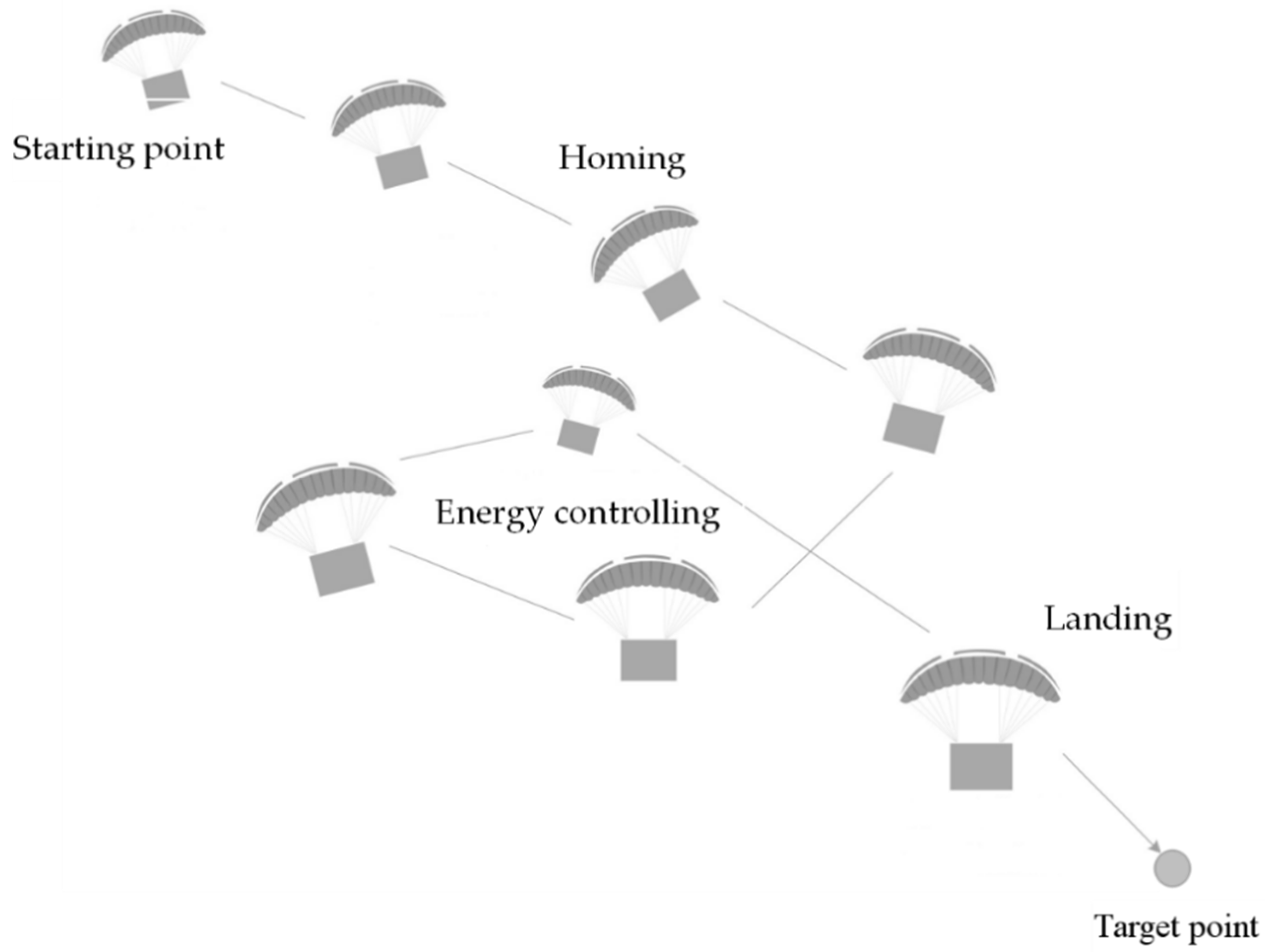
The parafoil airdrop system itself does not have a power device. By controlling the two pull-down parachute ropes on the left and right of the trailing edge, the parafoil can home autonomously. The entire segmented homing process can generally be divided into three parts: centripetal, energy control, and landing, as shown in Figure 1.

Figure 1.
Homing process of parafoil airdrop system.
Centripetal flight is used to reduce the distance difference between the airdrop system and the target point. Capability control flight is used to eliminate the high degree of redundancy existing in the airdrop system. Landing flight is mainly used to adjust the flight direction, which is prepared for the windward landing of the airdrop system.
2.2.1. Trajectory Design Scheme
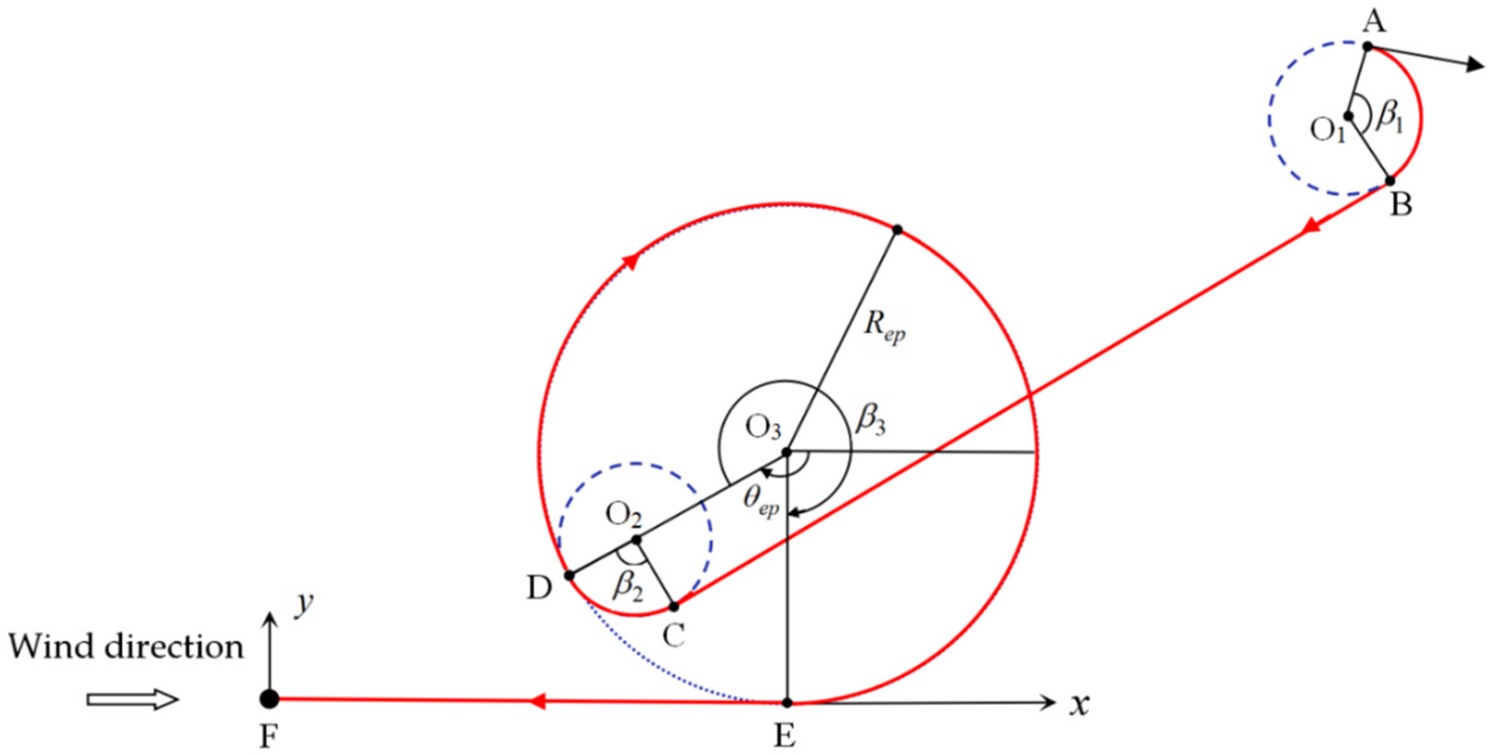
Based on the classical segmented trajectory design, this paper designed a new trajectory planning scheme, which not only considers the energy loss generated in the homing process, homing accuracy, and the overall flight safety of the system, but also takes into account the convenience of the bird landing operation. The specific scheme is shown in Figure 2.

Figure 2.
Diagram of trajectory design scheme.
In Figure 2, and are the two coordinate axes on the horizontal plane in the wind coordinate system. Axis is perpendicular to plane and intersects the plane at point F. The origin F of the wind coordinate system is set as the target point, and the wind direction is consistent with the -axis direction. Point A is the starting point of the airdrop system after parachute opening. After turning through arc AB, the parafoil airdrop system flies to the circling area near the target point, and point D is the entry point. Circle is the center of the circle in the circling area, and the parafoil airdrop system makes a turning flight around this point with as the radius, so as to reduce the flight altitude, and is the angle between the line connecting the two points D and and the positive direction of the -axis. EF is the upwind flight phase before entering the bird’s landing, and it is tangent to the circle .
In order to reduce the control frequency of the controller and reduce the energy loss generated as much as possible, the trajectory in Figure 2 is designed with a single-side pull-down control method. When the parafoil system needs to adjust the flight direction, in order to achieve the purpose of fast and safe adjustment, it turns with the minimum turning radius. As shown in Figure 1, the two arcs AB and CD are the flight direction adjustment sections, both of which are carried out with the minimum turning radius. The value range of the central angle corresponding to the two arcs is , , so as to reduce the control energy consumption as much as possible. The key to segment optimization is to determine the position of entry point D, which can be transformed into the calculation of the values of the two parameters and . In order to make the whole planned trajectory optimal, the objective function shown in Equation (3) is established to obtain the optimal values of parameters and .
In Equation (3), is the landing accuracy objective function, which represents the deviation between the landing point and the target point, where represents the length of the arc AB and CD, represents the length of the arc DE, and represents the length of line segments BC and EF, respectively, represents the horizontal flight distance corresponding to the initial height of the parafoil system, and is the glide ratio of the parafoil airdrop system.
2.2.2. Calculation and Constraints of Trajectory Parameters
Let be the coordinates of the initial point, represents the turning flight direction of the parafoil system, is the clockwise flight, is the counterclockwise flight, , is the initial heading angle, and the center positions of and are represented by and respectively, then the vector from to can be calculated by Equation (4):
The included angle between and the positive direction of the -axis can be calculated by Equation (5):
The included angles , and of the circular arc in Figure 1 can be calculated by Equations (6) and (7):
The parameter in Equation (6) can be obtained by Equation (8):
In order to save the control energy as much as possible and improve the safety and stability of the airdrop system during flight, the value ranges of the agreed parameters and are limited by Formula (9):
In Formula (9), is the minimum turning radius allowed by the parafoil airdrop system when flying in the hovering high-flying area, corresponding to the maximum unilateral pull-down range of the parachute rope, and is the maximum turning radius.
2.3. Trajectory Optimization
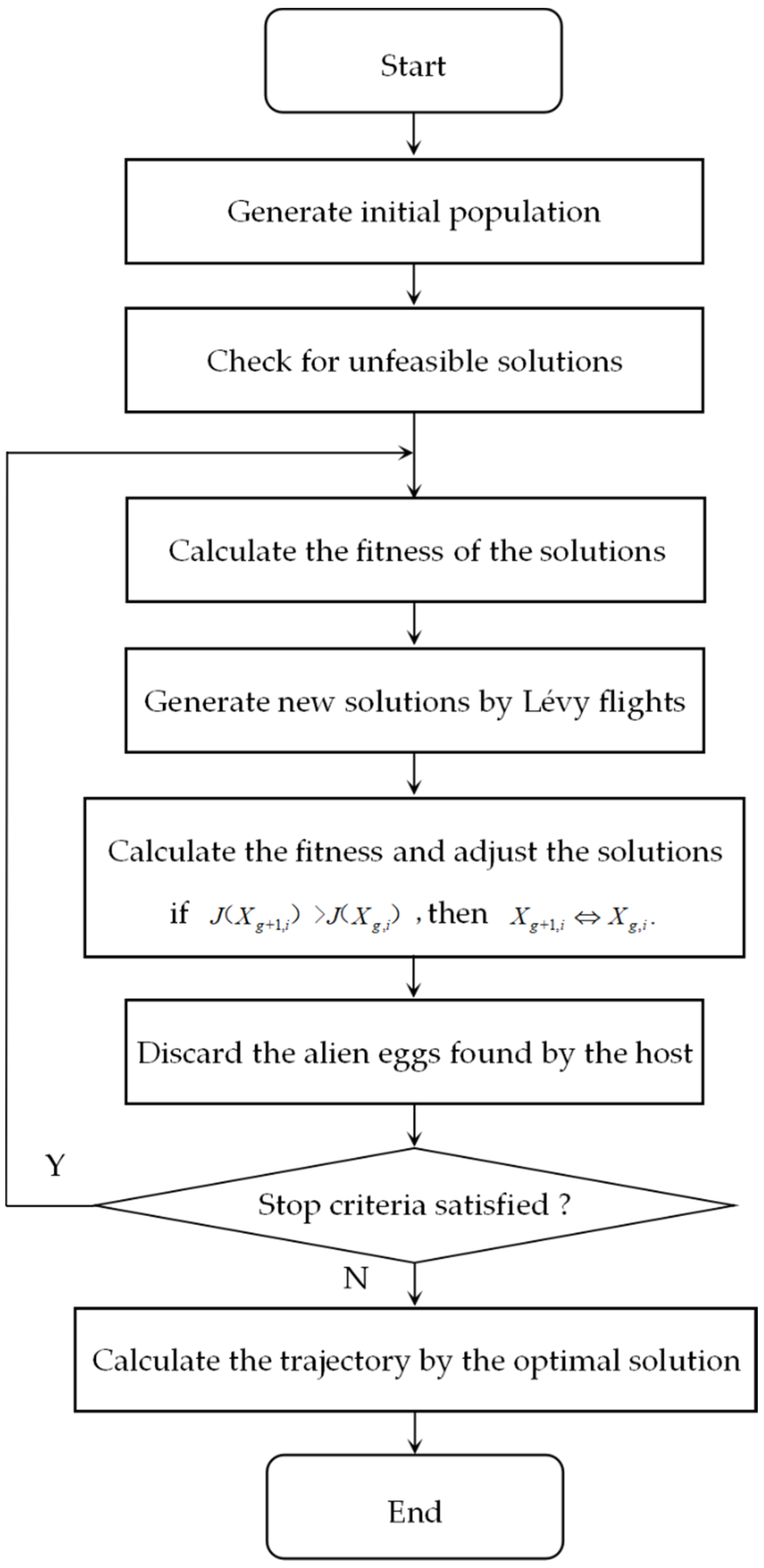
The cuckoo search (CS) algorithm was proposed in 2009 [27]. It is a bionic algorithm generated by imitating the cuckoo’s breeding and random flight behavior. The search process does not depend on the gradient and has the advantages of fewer parameters, high algorithm execution efficiency, and easy implementation. It has attracted the attention of many researchers. On this basis, many improved algorithms have been proposed to improve the overall performance of the algorithm [28,29,30], and, based on the CS algorithm, combined with the piecewise trajectory design scheme proposed above, this paper searched for the optimal solution for the objective function, shown in Equation (3), within the given interval of parameters and , and determined the trajectory. The specific implementation steps are shown in Figure 3.

Figure 3.
Flow chart of trajectory optimization.
Step 1: Initialize parameters, such as population size , the maximum number of iterations, the probability of the host discovering cuckoo eggs, the starting point coordinates , the initial direction , the radius and the angle range of the entry point, and other parameters. According to the value range shown in Formula (9), a two-dimensional initial population composed of and is randomly generated, and its fitness value is calculated using the objective function shown in Equation (3).
Step 2: Generate a new levy flight solution from Equation (10) where represents the -th solution in the -th generation, , , , and the parameter can be calculated by Equation (11):
Step 3: Calculate the fitness value J of solution A, and update the solution set according to the following rules:
Step 4: Update the solution set with the probability of the host finding the cuckoo egg, as shown in Equation (12), where is the Heaviside step function, and :
Step 5: Calculate the fitness value of the solution set updated by Equation (12), and update the solution set using the rules in Step 3, then, find and save the optimal solution in the new solution set. Judge whether the search end condition is satisfied; if not, skip to step 2 for loop execution. Otherwise, end the loop and find the global optimal solution.
Step 6: Substitute the obtained optimal parameter into Equations (4)–(8) to calculate the parameters of each segment, and calculate the corresponding homing trajectory according to the initial conditions and the point-mass model of the parafoil airdrop system.
3. Results
3.1. Parameter Setting
In order to prove the feasibility of the segmented trajectory planning scheme proposed in this paper, the trajectory optimization results were simulated and verified based on the point-mass model of the parafoil airdrop system and the cuckoo optimization algorithm. The relevant parameter settings in the trajectory optimization scheme and the cuckoo optimization algorithm are shown in Table 1.

Table 1.
Parameter setting.
In Table 1, the glide ratio f of the parafoil airdrop system was 3, its horizontal flight speed was 13.8 m/s, the vertical descent speed was 4.6 m/s, and the minimum turning radius was set as 100 m. The minimum and maximum of the radius of spiral height elimination were set as 100 m and 500 m, respectively. The headwind flight distance before bird landing was set as 100 m. Let the number of nests in the cuckoo optimization algorithm be 100. That is, the number of solutions was 100, the maximum number of iterations was 200, the probability of the host discovering cuckoo eggs was 0.25, the step scaling factor was 1, and was 1.5.
3.2. Result Analysis
The cuckoo optimization algorithm was used to solve the objective function shown in Equation (3), to obtain the optimal solutions of and , and, then, to determine the optimal trajectory. In order to ensure the comprehensiveness of the verification, Table 2 shows three different airdrop situations, and the simulation analysis of their trajectory planning was carried out, respectively. The simulation results are shown in the following figures.
Table 2.
Initial state setting.
3.2.1. Results of State 1
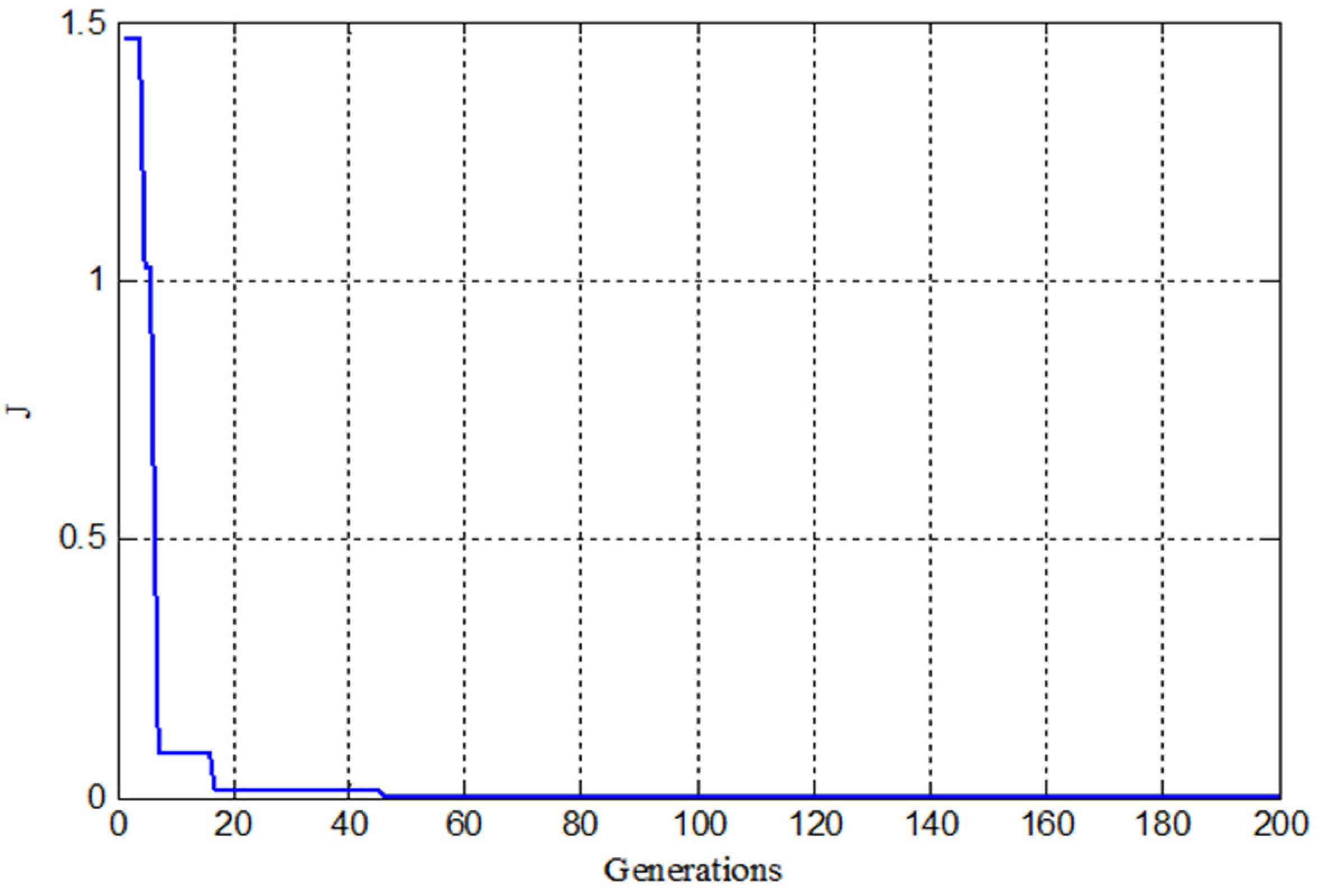
When the starting point of the parafoil airdrop system was at (800 m, −650 m, 1000 m), the optimal solution of the objective function was obtained through the cuckoo search algorithm, where rad, , and the objective function value was 0 at this time. Figure 4 shows the convergence curve when the objective function was optimized. It can be seen that the curve converged when the search reached 16 generations, and the convergence speed was faster.
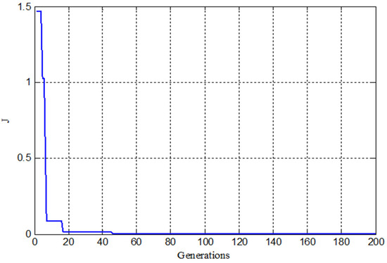
Figure 4.
Convergence curve of the objective function under the state 1.
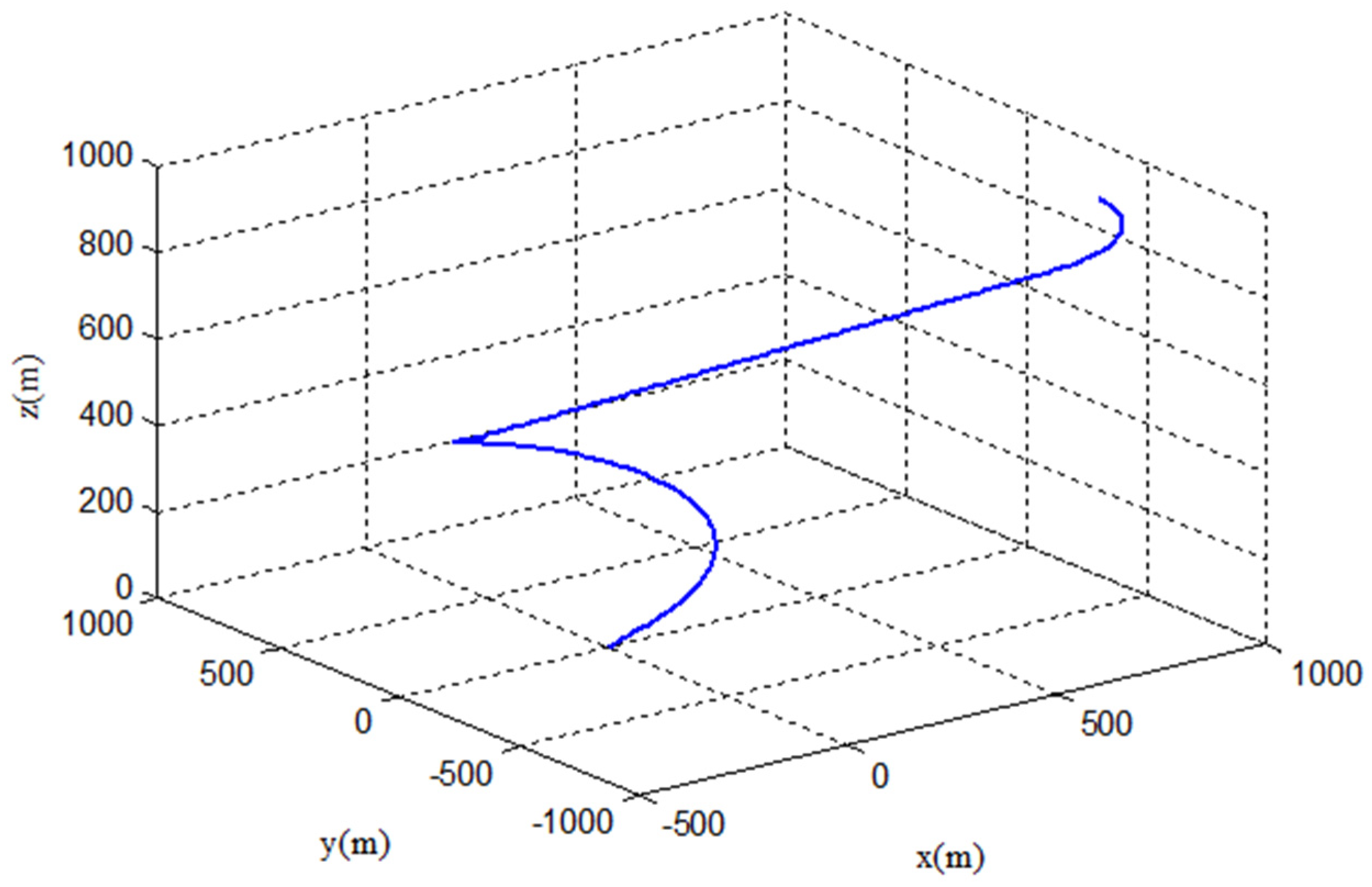
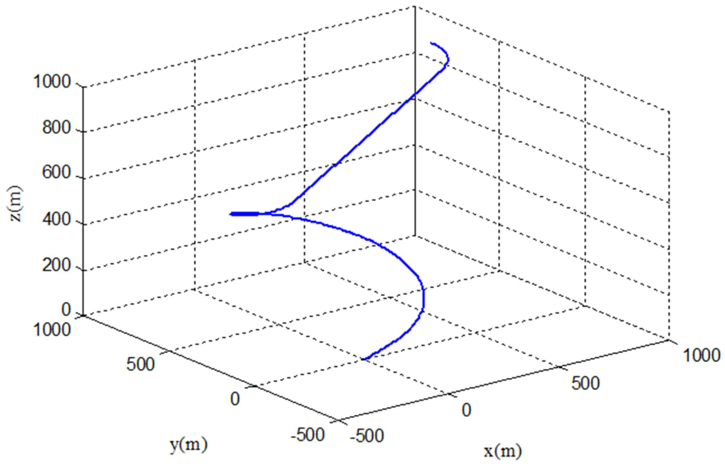
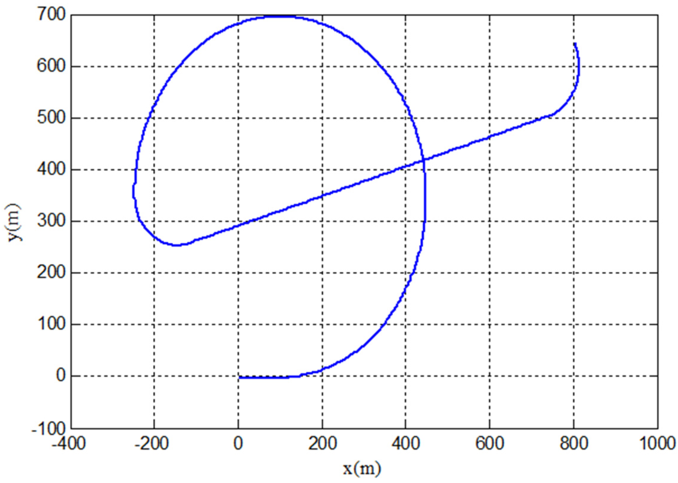
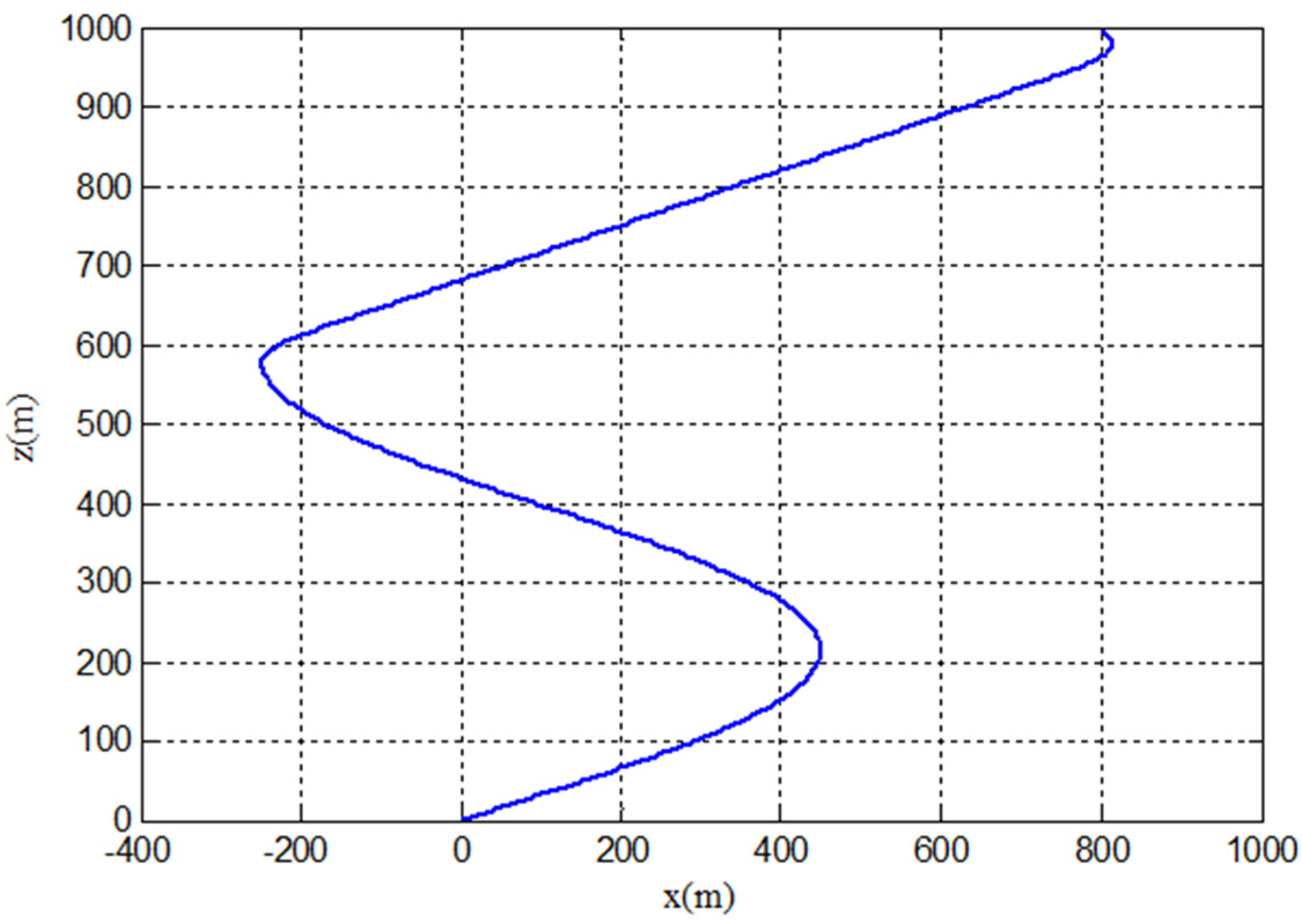
Figure 5, Figure 6 and Figure 7 are the effect diagrams of the trajectory planned by the new segmentation method. When the plane coordinates of the starting point of the parafoil airdrop system were at (800 m, −650 m), its position was at the lower right of the target point, and the starting flight direction was inconsistent with the direction of the target point. As can be seen from Figure 3, the planned trajectory firstly performed a turning flight to adjust the flight direction. The radian of the turning angle was about 2.9855 rad. After turning, the parafoil airdrop system entered the energy control area in the way of straight-line flight and minimum turning radius flight. In the energy control area, it made a circling and height elimination flight with a radius m, the turning flight was about 0.75 weeks, and the total radian was about 4.7124 rad. Finally, the airdrop system flew to the target point in a straight line along the tangent direction of the circle. The planned trajectory finally met the requirement of aligning with the headwind to the landing target point.
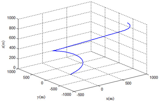
Figure 5.
Three-dimensional trajectory under the state 1.
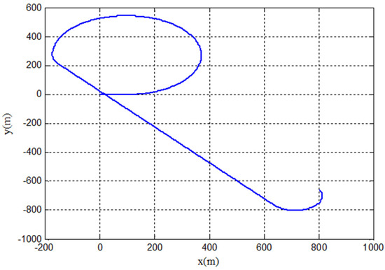
Figure 6.
Horizontal trajectory under the state 1.
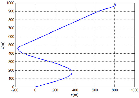
Figure 7.
Longitudinal trajectory under the state 1.
3.2.2. Results of State 2
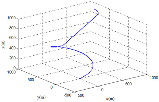
Figure 8.
Three-dimensional trajectory under the state 2.
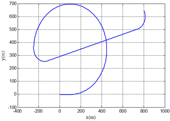
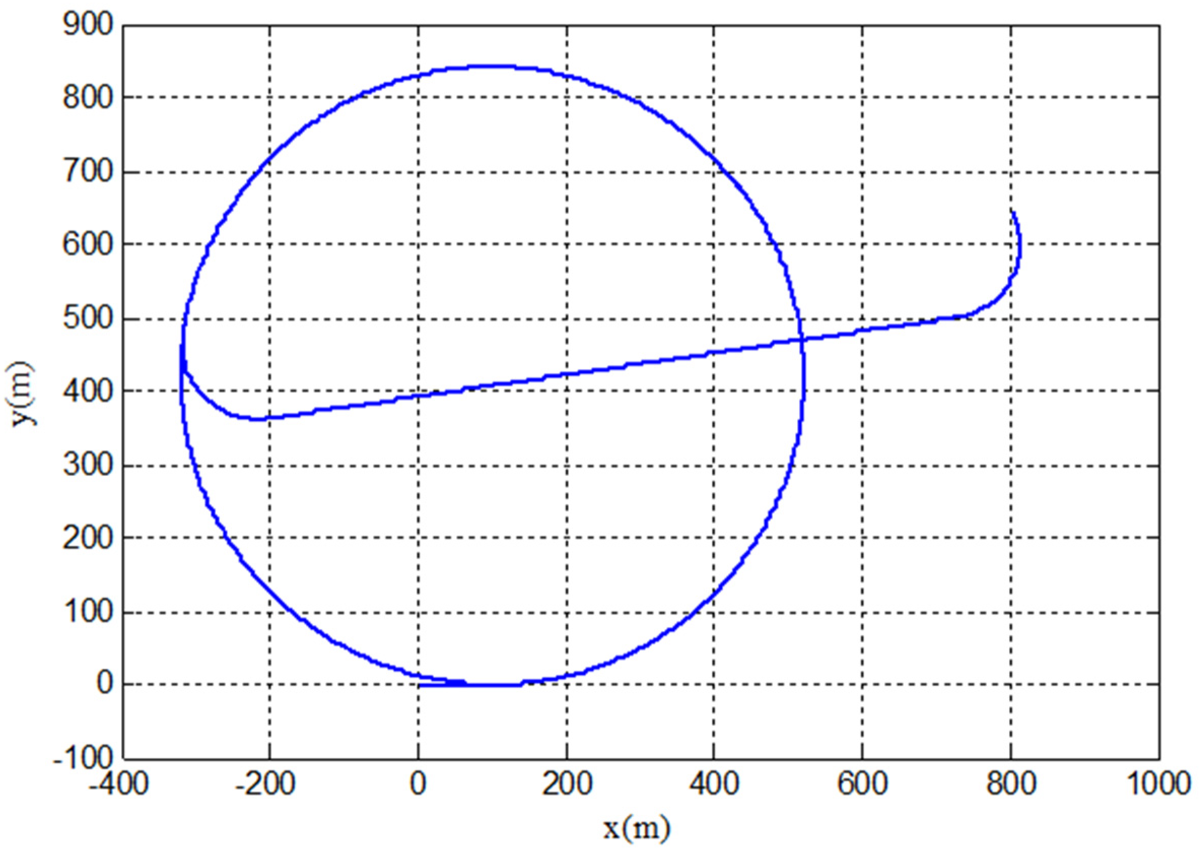
Figure 9.
Horizontal trajectory under the state 2.

Figure 10.
Longitudinal trajectory under the state 2.
In state 2, the starting point of the parafoil airdrop system was located at (800, 650, 1000), which was located at the upper right of the target point in the horizontal trajectory, and the airdrop height was consistent with state 1. The search algorithm was used to search for the optimal solution of the objective function, and the optimal entry point was located at , rad. It can be seen from the planned trajectory curve that, similar to state 1, the whole trajectory was still composed of turning towards the target point, flying straight to the energy control area, circling and height elimination, and upwind alignment. At this time, was 1.8173 rad and was 4.6877 rad.
3.2.3. Results of State 3
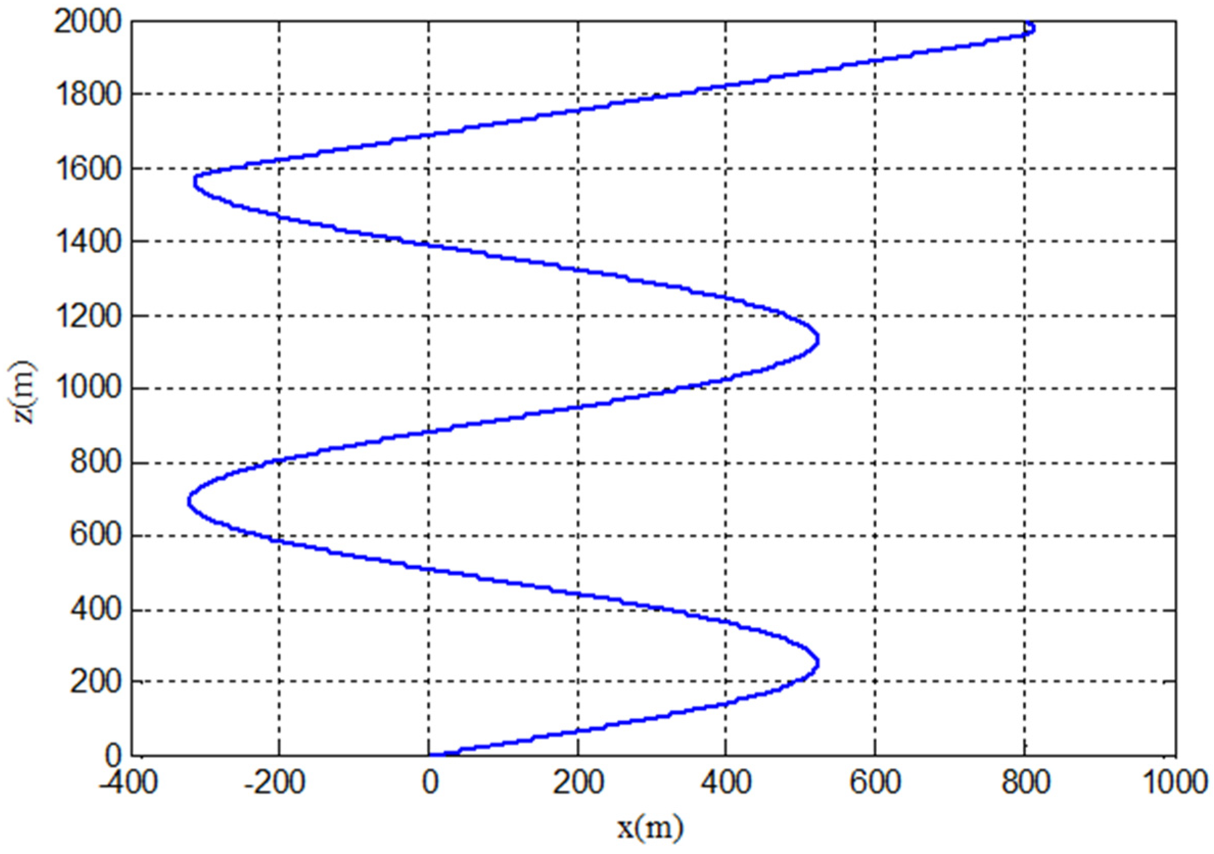
Figure 11, Figure 12 and Figure 13 are the effect diagrams of the trajectory planned by segments when the coordinates of the starting point were at (800 m, 650 m, 2000 m).The entry point obtained by searching the optimal solution of the objective function was located at , , and the angles of the two turning angles for adjusting the flight direction were , . The arc of the hovering height was , which meant the parafoil airdrop system hovered about 1.73 circles in the energy control area, and the elimination height was about 1526 m. The trajectory eventually entered the target point in the upwind direction.
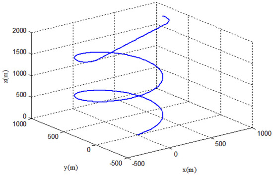
Figure 11.
Three-dimensional trajectory under the state 3.
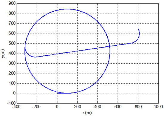
Figure 12.
Horizontal trajectory (state 3).
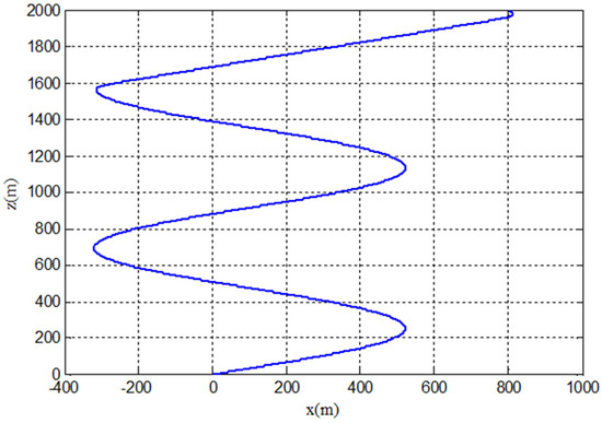
Figure 13.
Longitudinal trajectory under the state 3.
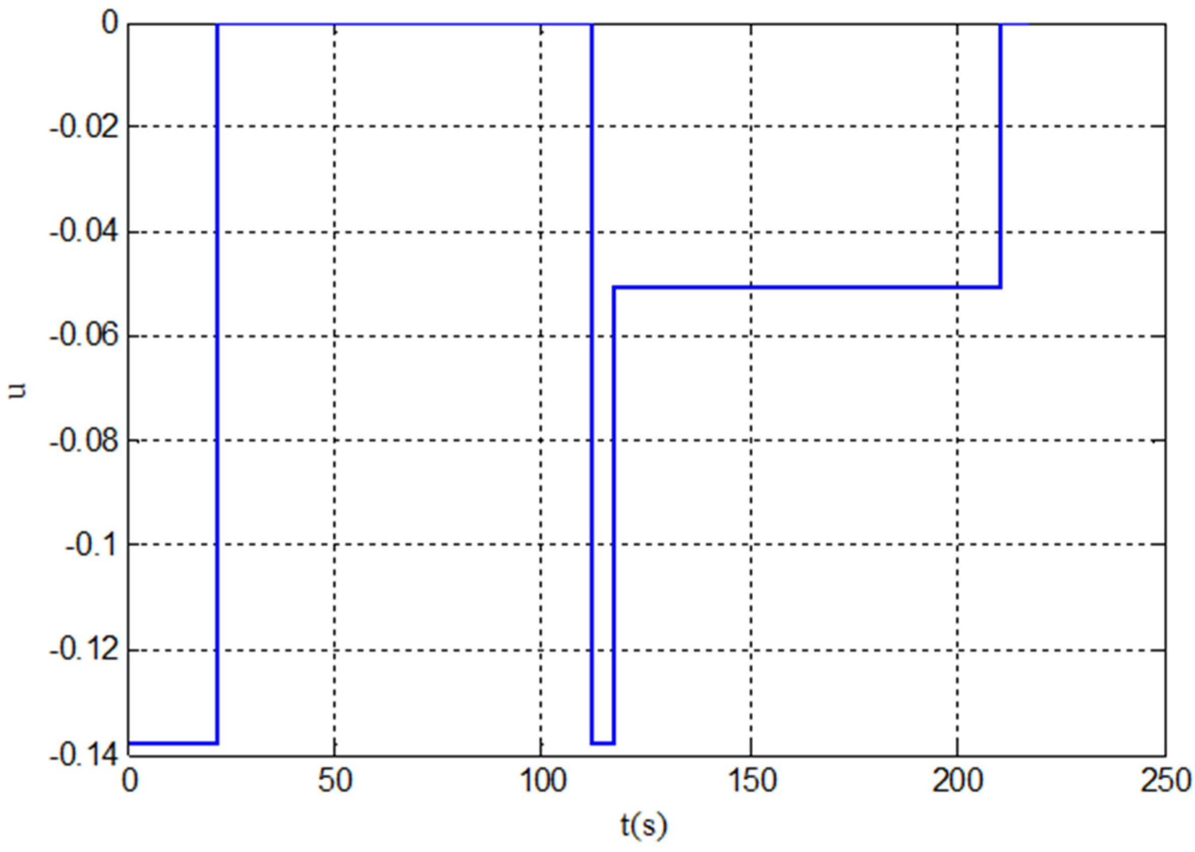
Figure 14, Figure 15 and Figure 16 are the control curves under three different airdrop situations, respectively, corresponding to the trajectories planned in stages, as shown in Figure 5, Figure 8 and Figure 11. It can be seen from the control curve that the control quantity corresponding to the homing trajectory planned by the segmental trajectory planning scheme proposed in this paper was a piecewise function, having a value less than zero, and the control quantity remained constant in the corresponding time period. This control was relatively simple in practical application, and the flight of the parafoil airdrop system was also relatively stable.
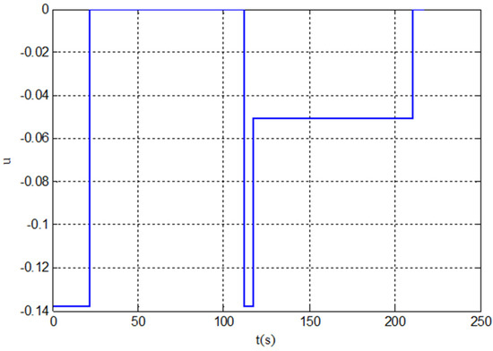
Figure 14.
Control curve under the state 1.
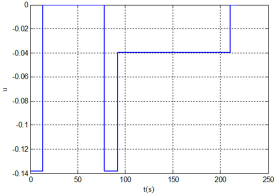
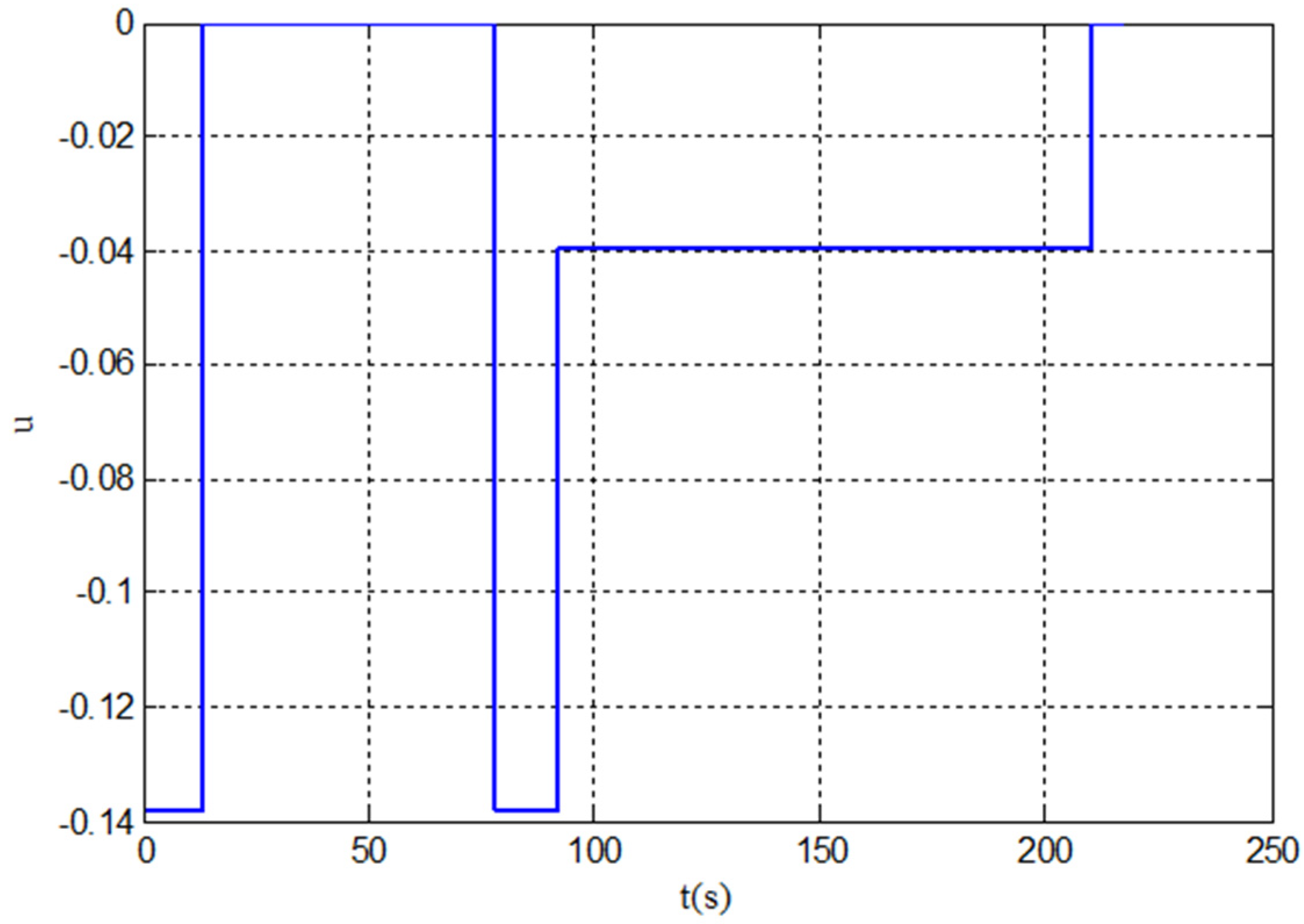
Figure 15.
Control curve under the state 2.

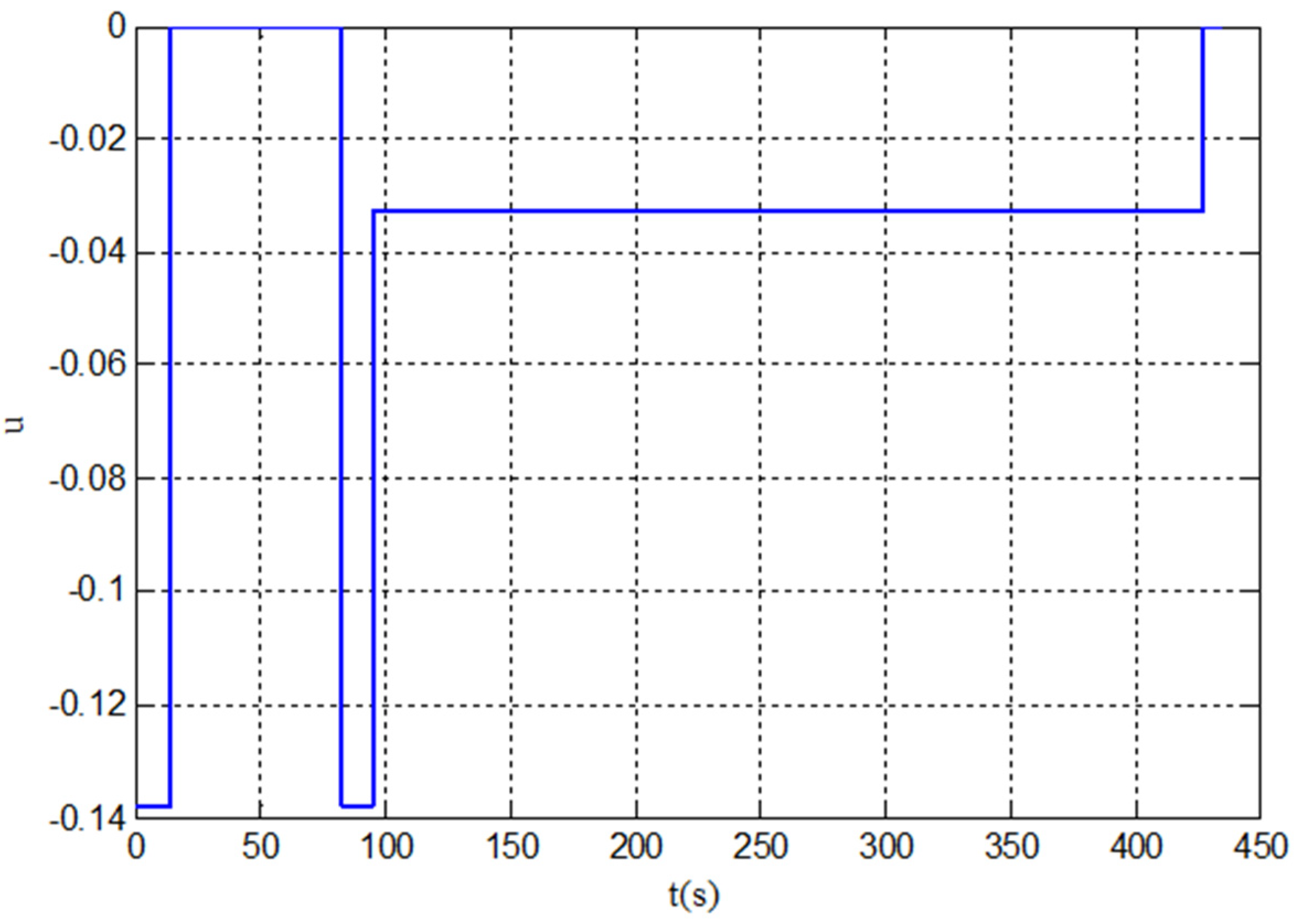
Figure 16.
Control curve under the state 3.
Table 3 shows the landing accuracy of the three trajectories at the target point. It can be seen that the lateral error of the landing was small, and the landing direction was opposite to the preset wind direction, which met the design requirements. In addition, a large number of simulation experiments showed that the optimization of the parameters of the trajectory optimization algorithm could be converged within 20 generations, showing good robustness.
Table 3.
Landing accuracy.
Comparing the segmented trajectory under the third airdrop cases with the first two, it can be seen that, due to the high position of the airdrop point in case 3 and the distance from the target point being farther than in cases 1 and 2, more time for circling and height elimination was required in the energy control area. On the contrary, if the airdrop altitude was too low and the distance from the target point far, the system would not have enough time to achieve the target landing. Therefore, for the unpowered parafoil airdrop system, its airdrop position needs to be reasonably selected.
4. Discussion
Under the same conditions, when considering the landing accuracy of the target point, the accuracy of the trajectory planned by the method in this paper is basically the same order of magnitude compared with the existing classical segmented trajectory method. For example, when the coordinates of the starting point were at (800, 800, 2000) and the initial flight direction , the landing direction of the segmented trajectory planning strategy proposed in this paper was 3.14, and the landing error was 0.6685 m, which was about 0.3742 m higher than the accuracy of 1.0427 m in Ref. [23].
Compared with the traditional classical segmented trajectory, the length of the glide trajectory before landing in the new scheme can be set freely according to the actual flight situation, which overcomes the defect of the length of the glide segment being affected by the radius of the parafoil circling flight circle, and has, therefore, higher landing accuracy and safety. Therefore, the segmented trajectory optimization strategy of the parafoil airdrop system given in this paper is effective and feasible.
It should be pointed out that the trajectory planning scheme designed in this paper is the basic optimal design method for the autonomous homing trajectory of the parafoil. The trajectory planning problem with constraints, such as obstacles and faults in the homing process, is not within the scope of this paper.
5. Conclusions
In the design scheme of the segmented homing of the parafoil airdrop system, the landing target point, or the position of executing the bird landing, is usually set at the center of the circling flight area. This method has the problem that the length of the straight flight segment before landing is affected by the helix radius. When the radius calculated by the optimization parameters is small, the gliding flight segment of the parafoil is shortened, which brings difficulties to the bird landing operation, or even failure to perform the bird landing successfully, resulting in damage to the airdropped material. In this paper, the segmentation scheme is improved. The straight flight segment before landing is designed at the tangent position of the spiral height elimination circle, and its length can be freely controlled. Compared with the target point designed at the center position of the spiral height elimination circle, it avoids the problem of the length of the straight flight segment before landing being subject to the spiral radius and provides a guarantee for bird landing in terms of landing accuracy and safety.
Based on the verification needs of the new trajectory scheme, this paper established the point mass model of the parafoil airdrop system. On the basis of analyzing the flight characteristics of the parafoil airdrop system, the segmentation idea and design method of the new scheme were introduced, and the calculation method of each segment trajectory analyzed. The calculation formula of the objective function and the constraint range of parameters and were given. The application method and steps of the parameter optimization of the cuckoo optimization algorithm in the new scheme were introduced in detail. In order to fully verify the feasibility of the new scheme, the trajectory under different airdrop conditions was simulated in this paper. The results showed that the correct trajectory could be successfully obtained under different initial conditions. Compared with the existing design schemes, the results show that the landing direction and accuracy of the new scheme can achieve ideal results, and the landing glide segment can be freely set and is no longer limited by the helix radius length, which proves the correctness and feasibility of the new trajectory design scheme. Moreover, the new scheme has the characteristics of simple control, high safety and easy realization in engineering. It is suitable for the trajectory planning of parafoil fixed-point airdrop systems before autonomous homing and also provides a new reference for the landing flight of parafoil airdrop systems. In future research work, we will consider more complex environmental constraints, such as obstacles, enemy areas, etc., so that the research results in this paper can be applied more widely.
Author Contributions
Conceptualization, H.G. and J.T.; methodology, H.G.; software, H.G.; validation, H.G.; formal analysis, H.G. and J.T.; writing—original draft preparation, H.G.; writing—review and editing, H.G. and J.T. All authors have read and agreed to the published version of the manuscript.
Funding
This research was funded by the Natural Science Foundation of Anhui Province, China, grant number 1808085MF183 and Anhui University Top-notch Talents Academic Funding Project under grant number gxbjZD2020079.
Acknowledgments
The authors would like to express their sincerely thanks to all reviewers and editors for their help in improving the quality of this paper.
Conflicts of Interest
The authors declare no conflict of interest.
References
- Yakimenko, O.A. Precision Aerial Delivery Systems: Modeling, Dynamics, and Control; American Institute of Aeronautics and Astronautics, Inc.: Reston, VA, USA, 2015; AIAA-2015-248. [Google Scholar]
- Sun, Q.L.; Li, Y.; Zheng, Y.M.; Tao, J.; Sun, H.; Sun, M.W.; Dehmer, M.; Chen, Z.Q. Trajectory tracking control of powered parafoil system based on sliding mode control in a complex environment. Aerosp. Sci. Technol. 2022, 122, 107406. [Google Scholar] [CrossRef]
- Sun, H.; Sun, Q.L.; Zeng, X.Y.; Luo, S.Z.; Chen, Z.Q. Accurate Homing of Parafoil Delivery Systems based Glide-Ratio Control. IEEE Trans. Aerosp. Electron. Syst. 2020, 56, 2374–2389. [Google Scholar] [CrossRef]
- Zhang, H.; Chen, Z.L.; Wei, J.B.; Su, L.J. Backstepping control method for path following of unmanned parafoil vehicle. J. Shanghai Jiao Tong Univ. 2016, 50, 1845–1852. [Google Scholar]
- Jann, T. Advanced features for autonomous parafoil guidance, navigation and control. In Proceedings of the 18th AIAA Aerodynamic Decelerator Systems Technology Conference and Seminar, Munich, Germany, 25–26 May 2005. [Google Scholar]
- Mpanza, L.J.; Pedro, J.O. Optimised Tuning of a PID-Based Flight Controller for a Medium-Scale Rotorcraft. Algorithms 2021, 14, 178. [Google Scholar] [CrossRef]
- Tan, P.L.; Sun, Q.L.; Chen, Z.Q. Application of active disturbance rejection control in trajectory tracking of powered paragoil system. J. Zhejiang Univ. (Eng. Sci.) 2017, 51, 992–999. [Google Scholar]
- Guo, Y.M.; Yan, J.G.; Wu, C.H.; Wu, C.; Xing, X. Autonomous homing design and following for parafoil/rocket system with high-altitude. J. Intell. Robot. Syst. 2021, 101, 73. [Google Scholar] [CrossRef]
- Zhang, M.; Hu, W.; Ji, S.; Song, Q.; Gong, P.; Kong, L. Vision-Assisted Landing Method for Unmanned Powered Parachute Vehicle Based on Lightweight Neural Network. IEEE Access 2021, 9, 130981–130989. [Google Scholar] [CrossRef]
- Gao, H.T.; Jin, T.; Dehmer, M.; Emmert-Streib, F.; Sun, Q.L.; Chen, Z.Q.; Xie, G.M.; Zhou, Q. In-Flight Wind Field Identification and Prediction of Parafoil Systems. Appl. Sci. 2020, 10, 1958. [Google Scholar] [CrossRef]
- Long, X.; Sun, M.; Piao, M.; Chen, Z. Parameterized Trajectory Optimization and Tracking Control of High Altitude Parafoil Generation. Energies 2021, 14, 7460. [Google Scholar] [CrossRef]
- Omar, H.M. Optimal Geno-Fuzzy Lateral Control of Powered Parachute Flying Vehicles. Aerospace 2021, 8, 400. [Google Scholar] [CrossRef]
- García-Beltrán, C.; Miranda-Araujo, E.; Guerrero-Sanchez, M.; Valencia-Palomo, G.; Hernández-González, O.; Gómez-Peñate, S. Passivity-Based Control Laws for an Unmanned Powered Parachute Aircraft. Asian J. Control. 2021, 23, 287–296. [Google Scholar] [CrossRef]
- Tao, J.; Sun, Q.L.; Zhu, E.L.; Chen, Z.Q.; He, Y.P. Genetic algorithm based homing trajectory planning of parafoil system with constraints. J. Cent. South Univ. (Sci. Technol.) 2017, 48, 404–410. [Google Scholar]
- Sun, H.; Sun, Q.L.; Luo, S.Z.; Chen, Z.Q.; Wu, W.N.; Tao, J.; He, Y.P. In-Flight compound homing methodology of parafoil delivery systems under multiple constraints. Aerosp. Sci. Technol. 2018, 79, 85–104. [Google Scholar] [CrossRef]
- Zhang, L.M.; Gao, H.T.; Chen, Z.Q.; Sun, Q.L.; Zhang, X.H. Multi-Objective global optimal parafoil homing trajectory optimization via Gauss pseudospectral method. Nonlinear Dyn. 2013, 72, 1–8. [Google Scholar] [CrossRef]
- Gao, H.T.; Zhang, L.M.; Sun, Q.L.; Sun, M.W.; Chen, Z.Q.; Kang, X.F. Fault-tolerance design of homing trajectory for parafoil system based on pseudo-spectral method. Control. Theory Appl. 2013, 30, 702–708. [Google Scholar]
- Chen, Z.M.; Guo, D.Y.; Lin, Y. A Deep Gaussian Process-Based Flight Trajectory Prediction Approach and Its Application on Conflict Detection. Algorithms 2020, 13, 293. [Google Scholar] [CrossRef]
- Luo, S.Z.; Sun, Q.L.; Tan, P.L.; Tao, J.; He, Y.; Luo, H. Trajectory planning of parafoil system with intricate constraints based on Gausspseudo-spectral method. Acta Aeronaut. Astronaut. Sin. 2017, 38, 320363. [Google Scholar]
- Sun, H.; Luo, S.Z.; Sun, Q.L.; Tao, J.; Luo, H. Trajectory optimization for parafoil delivery system considering complicated dynamic constraints in high-order model. Aerosp. Sci. Technol. 2020, 98, 105631. [Google Scholar] [CrossRef]
- Sun, H.; Sun, Q.L.; Chen, Z.Q.; Tao, J. Trajectory planning for parafoil system considering dynamic constraints in complicated environment. Aerosp. Sci. Technol. 2021, 42, 324301. [Google Scholar]
- Jiang, H.C.; Liang, H.Y.; Zeng, D.T.; Yan, J. Design of the optimal homing trajectoryof a parafoil system considering threat avoidance. J. Harbin Eng. Univ. 2016, 37, 955–962. [Google Scholar]
- Gao, H.T.; Tao, J.; Sun, Q.L.; Chen, Z.Q. Design and optimization in multiphase homing trajectory of parafoil system. J. Cent. South Univ. 2016, 23, 1416–1426. [Google Scholar] [CrossRef]
- Chen, Q.; Zhao, M.; Li, Y.H.; He, Z.Y. Optimal segment constant trajectory planning for parafoil system based on gradient descent method. Acta Aeronaut. Astronaut. Sin. 2020, 41, 324226. [Google Scholar]
- Gao, H.T. Research on Control and Autonomous Homing Trajectory Planning of Parafoil System. Ph.D. Thesis, Nankai University, Tianjiin, China, 2014. [Google Scholar]
- Lee, S.J.; Conner, J.C., Jr.; Arena, A.S., Jr. An Autonomous Recovery System for High Altitude Payloads by Using a Parafoil. In Proceedings of the AIAA Atmospheric Flight Mechanics Conference, Atlanta, GA, USA, 16–20 June 2014. [Google Scholar]
- Yang, X.S.; Suash, D. Engineering optimisation by cuckoo search. Int. J. Math. Model. Numer. Optim. 2010, 1, 330–343. [Google Scholar] [CrossRef]
- Feng, Y.; Zhou, J.Z.; Mo, L.; Wang, C.; Yuan, Z.; Wu, J. A Gradient-Based Cuckoo Search Algorithm for a Reservoir-Generation Scheduling Problem. Algorithms 2018, 11, 36. [Google Scholar] [CrossRef] [Green Version]
- Zhang, Y.Y.; Jin, Z.G. An improved cuckoo search for multimodal optimization problems. J. Harbin Inst. Technol. 2019, 51, 89–99. [Google Scholar]
- Fu, W.Y. Cuckoo search algorithm with gravitational acceleration mechanism. J. Softw. 2021, 32, 1480–1494. [Google Scholar]


Publisher’s Note: MDPI stays neutral with regard to jurisdictional claims in published maps and institutional affiliations. |
© 2022 by the authors. Licensee MDPI, Basel, Switzerland. This article is an open access article distributed under the terms and conditions of the Creative Commons Attribution (CC BY) license (https://creativecommons.org/licenses/by/4.0/).