1. Introduction
The beam reflected off an interface experiences spatial and angular shifts depending on its polarization and profile. The spatial displacements constitute the well-known Goos-Hänchen (GH) shift in the plane of incidence [
1,
2]. In [
3], the first observation of the GH shift of a light beam incident on a bare metal surface was reported. The physical origin of the lateral GH shift lies in the angular dispersion of the Fresnel reflection coefficients. The phase changes of plane waves with different wavenumbers combine together to generate the GH shift. Usually, the GH shift is of the order of the wavelength. Detecting such a small GH shift is not an easy task, so significant increase is necessary for practical applications. Various methods to enhance the shifts were considered. The displacement of the order of the beam width was shown for multilayered structures in [
2]. Significant enhancement of the GH shift is obtained by the excitation of surface plasmon waves on metal surfaces [
4,
5,
6] and Bloch surface electromagnetic waves in photonic crystals [
7]. Different materials and structures were considered to enhance the GH effect. The enhancement has been shown using weakly absorbing slabs [
8], gradient meta-surfaces [
9], subwavelength gratings [
10], graphene [
11] and a coherent medium [
12]. In [
13], beam shifts or corrections with respect to geometrical optics caused by the wave effects in a graded-index optical fiber were investigated. An angular shift of a beam at an air–glass interface was experimentally demonstrated in [
14]. A noticeable increase in angular displacement can be observed for a tightly focused beam reflected by a dielectric interface near the Brewster angle [
15]. The existence of large positive and negative GH shifts in photonic crystal mirrors was demonstrated in [
16]. In [
17], the negative GH shift on a two-dimensional photonic crystal with an effective negative refractive index was investigated by simulation and experiment.
Recently, the composite GH shifts have been investigated and experimentally observed at the air–Au interface [
18]. The composite GH shift of a Gaussian optical beam reflected at a glass–air interface in the visible and near-infrared regimes was experimentally investigated [
19]. The combined effect of the GH shift and the angular deviations generated by the transmission through the incoming and outgoing interfaces of the triangular prism was also analyzed [
20]. The spatial and angular GH and Imbert-Fedorov (IF) shifts of
p-polarized light are significantly enhanced around the resonant angle of SPR. The enhanced temperature-dependent composite GH and IF shifts were employed for temperature sensing [
21].
Large lateral displacements of beams incident upon a diffractive structure under resonance conditions can also be observed [
5]. Large GH effects are also expected for dielectric gratings [
4]. The GH angular shifts of several hundred microradians reinforced by the excitation of the SPR in a dielectric grating on a gold surface were demonstrated in [
22]. However, the effects of the incident beam width and subwavelength grating height on the plasmon enhanced GH shifts have not yet been studied.
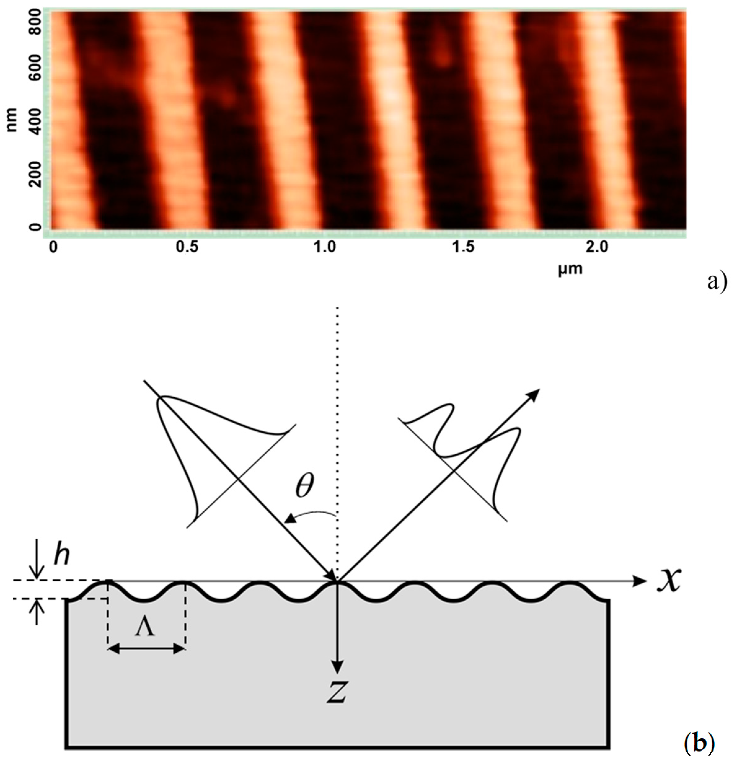
In this paper, we investigate the GH shift when the surface plasmon resonance is excited in a subwavelength nickel grating with a period Λ = 400 nm (
Figure 1). The effects of angular shift and beam shape change on the reflected beam near the surface plasmon resonance condition are demonstrated experimentally and confirmed by rigorous electromagnetic simulations. A significant increase in the angular GH shift is achieved at an optimal grating depth
h = 80 nm and a resonance angle of incidence
33.53°, corresponding to the optimal condition for the coupling of incident light with a surface plasmon. A significant increase in the angular shift with a decrease in the width of the incident beam is shown.
2. Surface Plasmon Resonance in Subwavelength Grating
A rigorous electromagnetic theory based on the
C-method is used for the calculations [
23]. Note that an
s-wave does not excite surface plasmon waves, so we consider the GH shift only for a
p-polarized incident wave.
The angle of incidence
, corresponding to the plasmon resonance, is determined by [
10,
24,
25]:
where
is the angle of incidence,
is the wavelength,
m is an integer,
is the grating period and
, is the real part of the dielectric constant of a grating.
Figure 2 presents the diffraction efficiencies of
Ni gratings with a period Λ = 400 nm depending on the angle of incidence for different grating depths.
It can be seen that the Wood and Rayleigh anomalies [
26] occur at the corresponding incidence angles. The minimum zero reflection is achieved when the grating depth
h becomes
hopt = 80 nm. This indicates that there is an effective coupling to the plasmon wave. As the grating depth decreases or increases relative to the optimal depth, the value of the minimum reflection coefficient increases. Note that the optimal depth depends on the grating material. It was shown in [
10] that the optimal depth for the silver grating is
h = 20 nm. The optimal grating depth, similar to the optimal thickness of the metal layer observed in [
6], corresponds to the excitation of the surface plasmon where the resonant absorption is just balanced by radiation damping and internal damping. The minimum in the reflectance is due to destructive interference between the leakage radiation and the reflected part of the excitation beam. The absorption and radiative losses determine the width of the SPR:
. The absorption losses are defined by the material dispersion
, while the radiative losses
depend on the grating profile and increase with an increase in depth
h [
27]. It can be shown that the minimum reflection is achieved if the radiation loss is equal to the damping due to absorption [
27]. This corresponds to the optimal coupling of the incident beam to the plasmon.
The absorption losses are defined by the imaginary part of the SP wave vector:
where
is the dielectric constant of nickel.
The radiation damping can be defined as
, where
lp is the plasmon path length. It follows from the calculations that the losses of the plasmons in a nickel grating with a period Λ = 400 nm and a depth
h = 80 nm are equal to α = 3055 cm
−1. For a depth of
h = 30 nm, plasmon losses are equal to 1500 cm
−1 [
10].
The minimum reflection is defined as .
In
Figure 3 the diffraction efficiencies of the
Ni gratings depending on the angle of incidence for different radii
w0 of the incident beam are presented.
The influence of the incident beam width on the reflectivity is significant for the incidence angles at which plasmon resonance occurs. For highly focused beams, the effect of plasmon resonance is significantly reduced because of the fact that most of the angular components of the incident beam spectrum are not phase-matched with the surface plasmon modes. It was shown in [
2] that the incident beam width should be greater than the propagation range of the surface plasmon mode in order to efficiently transfer energy to the plasmon field. The characteristic lengths
lp are determined by the losses of plasmons. In our case
μm. This indicates that the beam width
w should be greater than 3.27 μm. Indeed, with a beam width of
w0 = 7 μm or more (
Figure 3), almost all the incident power is absorbed by the grating, i.e., the incident energy is converted into surface plasmons.
In
Figure 4a, the results of calculations and measurements of diffraction efficiency of the zero order of the nickel grating depending on the angle of incidence of the radiation with
p-polarization are presented. It is seen that the effect of plasmon resonance occurs at the incidence angle of ~33° (
Figure 4a). At a relief depth of
h = 80 nm and incidence angle of
33.53°, almost all incident energy is absorbed by the grating (
Figure 4a). Note that this depth corresponds to the plane wave minimum reflection at the resonance incidence angle.
It can be seen that zero reflection (Wood anomaly) is not achieved and the Rayleigh anomaly is less pronounced in measurements due to the finite angular convergence of the incident Gaussian beam.
In
Figure 4b, the results of the calculation and measurements of diffraction efficiency of the zero order of the nickel grating with a period
= 400 nm and depth
h = 40 nm depending on the angle of incidence of the radiation are presented. As can be seen, unlike a grating with a depth of
h = 80 nm (
Figure 4a), the reflectivity is significant even at a resonant incidence angle. This means that there is no effective transfer of incident energy to surface plasmons at a grating depth of
h = 40 nm.
Goos-Hanchen Shift
In
Figure 5, the calculated intensity profiles of the reflected beam at a grating surface are presented under the surface resonance condition. While the negative lateral shift of the order of the beam radius occurs (
Figure 5a), there is no angular shift (
Figure 5b). Besides, the beam focusing in the reflection from the grating is also observed. It can be seen that the divergence angle of the reflected beam under the SPR condition almost two times larger than that of the incident beam
(
Figure 5b). Increase in the beam divergence angle is due to the beam reshaping at the grating surface.
Note that the effect of near-field beam focusing by a flat dielectric subwavelength grating was also demonstrated in [
28].
In
Figure 6 the angular intensity profiles of the reflected beam are presented for different values of the incident angle. It can be seen that the minimum intensity value in the dip corresponds to the incidence resonant angle because of the absorption of the field components with
corresponding to the SPR (
Figure 6c). The transition between positive and negative angular shifts is observed when the angle of incidence deviates from the resonant one. When moving away from the resonant angle of incidence, only one reflected beam remains (
Figure 6f). This indicates that, because of the existing shape of the reflection function (
Figure 2), the components with higher spatial frequencies will mainly be reflected.
Figure 7 shows the spatial intensity profiles depending on the transverse
x coordinate for different incidence angles at a distance of
z = 11 cm from the grating surface.
The appearance of two peaks around the incidence resonant angle is due to the presence of a dip in the reflectivity curve (
Figure 2). While the central part of the dip with a minimum reflection coefficient leads to the disappearance of the reflected light of the incident Gaussian beam, the left and right sides of the dip with a higher reflectivity lead to the creation of two peaks. Two equal peaks appear when the angle of incidence is equal to the resonance angle.
Angular GH shift and reshaping of the reflected beam is due to intensity and phase redistribution caused by the SPR. For a Gaussian beam with a certain width in
, the absorption on the plasmon depends on the wavevector
or angle
. Since the distribution over
is multiplied by reflection coefficient with a minimum at the center of the resonance (
Figure 2), the result is a distribution with two peaks.
The angular spectrum components of a Gaussian beam incident at a plasmon resonance angle
is located in the region
This means that the incident beam wave vectors at a resonance condition are located in the region
where
.
Note that the angular distance between two peaks is determined by the value , i.e., the narrower the beam, the greater the distance between the peaks.
At a resonant angle of incidence of a wide beam (an angular spectrum range is narrower than the dip width), the splitting of the reflected beam is not observed (
Figure 8a). However, there is a spatial negative displacement of the beam (
Figure 8b). It follows from the wave-vector matching condition (1) that the plasmon mode is excited in -1 diffraction order of the incident beam. This indicates that, under resonance conditions, the plasmon wave moves on the grating in a negative direction [
10]. Accordingly, the part of the incident beam energy is shifted backwards. The plasmon wave, in turn, is in resonance with the wave reflected in the zero order and begins to radiate into this wave (to pump energy into the reflected wave), but since the radiation does not occur instantly and the plasmon wave has a noticeable path length, the maximum of the re-emitted wave is shifted along the longitudinal coordinate
x in the direction of the plasmon wave propagation.
In
Figure 9, the calculated angular GH shifts depending on the angle of incidence for different beam widths are presented. The negative shifts can be observed for the incidence angles that are smaller than the critical one and the positive shifts for the angles that are greater than the critical one. It can be seen that a significant increase in the GH shift occurs near the critical angle corresponding to the Wood anomaly. The visible negative shifts can be observed near the Rayleigh anomaly for the focused beams. It follows that the higher angular shifts occur for the beams with a smaller width near the surface plasmon resonance.
Figure 10 shows the GH shifts depending on the angle of incidence for the grating depth that differs from the optimal one. It follows that the values of the angular GH shifts decrease significantly if the grating depth is not optimal for the effective coupling of the incident wave to the SP wave. In contrast to the case of the optimal depth
h = 80 nm (
Figure 9c,d), the GH shifts decrease by about 10 times. This indicates a significant role of SP resonance in the enhancement of the GH shift.
3. Measurement of the Angular GH Shift
In
Figure 11 the experimental setup consisting of the He-Ne laser, half-wave plate, focusing lens, subwavelength grating and Thorlabs CCD camera beam profiler is presented. The measurements show that no GH shift for an
s-polarized beam, and the effect of the reflected beam shape changing.
The adjustment of all these devices and optical elements and the choice of the distances between them were carried out in accordance with the simulation results. The change in the reflected beam radius with distance
z is determined by the expression:
where
is the radius of the laser beam where the intensity is
.
The radius of the beam
w(
z) is related to the full width at half maximum (FWHM) of the intensity distribution according to:
. For the He-Ne laser beam with an initial waist of
D = 0.75 mm, a wavelength
λ = 632.8 nm and a focusing lens with a focal length of
f = 50 mm, we have a focusing spot with a radius of 27
:
This value corresponds to the
. In
Figure 12, the incident beam intensity profile at a lens focal plane is presented.
Note, that the measurements include both spatial and angular shifts. While the contribution of the angular GH shift increases linearly as the beam propagates in accordance with
, the lateral GH shift
D is constant with the propagation distance
z (
Figure 13).
Our measurements were carried out at the distances where the spatial shift is much smaller than the angular displacement, i.e., . Indeed, when spatial shifts are only of the order of a few tens of micrometers, the displacements caused by angular shift are of the order of a millimeter at a distance of 10 cm.
It is of interest to evaluate the effect of defocusing on the GH shift when a slight discrepancy between the focusing plane and the grating surface appears because of an inaccurate choice of the distance between the source and the grating surface. It follows from the simulation and measurements that the mismatch of the focusing plane with the grating surface of less than 1 mm does not have a noticeable effect on the GH shift. It is known that there is no significant change in the width and curvature of the wavefront within the depth of focus. Indeed, the focusing depth of a Gaussian beam is determined by the Rayleigh distance or Rayleigh range, which, in our case, is equal to mm.
The GH shifts are determined by comparing the positions of the peaks of the reflected beams with s- and p-polarizations. Note that the reflection angle of the s-polarized beam is equal to the incidence angle, while the p-polarized beam deviates from the Fresnel angle of reflection.
In
Figure 14, the measured intensity profiles for different angles of incidence are presented at the distance
z = 11 cm from the grating surface.
It follows from the measurements that splitting into two beams separated by an angular shift occurs for the focused beam incident at a SPR angle (
Figure 14c). The high sensitivity of the GH angular shift to the light beam incidence angle near the surface plasmon resonance is demonstrated. It is seen that the reshaping of the beam profile from the Gaussian one or splitting it into two beams takes place when the incident angle is close to the plasmon resonance condition. The beam width and grating depth are the parameters that significantly affect the reflected beam profile. With the precise resonance, two equal peaks in the angular intensity distribution are observed (
Figure 14b). This indicates that the subwavelength grating can work as a beam splitter. The transition between the positive and negative shifts is observed by the variation of the angle of incidence. The deviation of the incidence angle in one direction or another from the resonant angle leads to the appearance of asymmetry in the intensity distribution. There are visible changes in the reflected beam shape when the incidence angle changes even by 1 angular minute.
In
Figure 15 the calculated spatial intensity profiles depending on the transverse
x coordinate for different incidence angles at the distance
z = 11 cm from the grating surface are presented.
It follows from the numerical calculations that the beam profiles and GH shifts for various incidence angles are in good agreement with the experiment. It can also be seen that the calculated widths of the reflected beams are equal to the measured values. A significant change in the beam shape occurs when the beam is incident under resonance condition. However, the Gaussian shape persists after the reflection of the incident beam from the grating surface outside the region
. In
Figure 16, the measured intensity profiles for various angles of incidence that are located outside the region
, at the distance
z = 11 cm from the grating surface are presented.
In
Table 1 the theoretical and experimental results are presented for different incident angles.
In the experiment, an angular shift of 0.30 degrees (
was demonstrated for a nickel grating under SPR, which is confirmed by modeling. Note that the increase in the angular shift is almost 100 times compared to the known results obtained for the diffraction grating [
22]. Such an increase in the angular deviation is achieved by the appropriate adjustment of the grating depth to achieve the optimal SP coupling condition. A visible transformation of the reflected beam shape is observed when the angle of incidence changes by a small amount. Even 1 angular minute (
rad) change in the incidence angle causes a noticeable reshaping of the reflected beam profile.
It follows that the measured angular GH shifts are in excellent agreement with the simulation results.
4. Discussion
Thus, the effect of angular GH shift for a visible light beam under the excitation of surface plasmon resonance (SPR) in a metal subwavelength grating is investigated using rigorous electromagnetic calculations and direct measurements. The SPR enhanced negative and positive angular GH shifts are demonstrated for the reflected beam from the grating with optimal depth. The high sensitivity of the GH shift and beam reshaping to the angle of incidence of the focused light beam near SPR is experimentally demonstrated.
It can be seen that the simulation results are in good agreement with the measurements. The numerical simulation with a Gaussian beam demonstrates the effects of the GH shift and beam reshaping observed in the experiment. The presence of negligible differences between the simulated and experimentally measured GH shifts can be due to the deviations of the grating profile from the sinusoidal one and due to surface roughness on the metal grating. In [
29], the effect of the surface roughness on the of a metal grating for SPR sensors was demonstrated. It was shown in [
30] that the SPR sensors based on a trapezoidal grating have great resistance to changes in grating parameters and relatively high performance.
Currently, there are various results of measurements of angular GH shifts of a Gaussian optical beam reflected at the air–glass interface near the Brewster angle [
14], at the glass–air interface [
19], at the air–Au interface [
18], at the prism–Au interface in the Kretschmann configuration [
31] and in a grating structure [
22]. Angular shifts of 60 μrad were observed in [
18] for a beam waist of 169 μm at a critical angle of incidence. In [
14], it was found that the measured angular deviation ranges from 10 to
μrad. Angular GH shifts up to
μrad were observed at the prism-Au interface when the incident beam was tightly focused to a 5 μm beam waist [
31]. Angular GH shifts of the order of several hundred micrometers were demonstrated for a focused beam using a simple gold (Au) film on a substrate to excite surface plasmons [
22]. Here we present the first results of observing the angular GH shifts of the light beam incident on a metal subwavelength grating.
Although the physical aspects of the GH shifts are well described in many publications, the effect of the beam width and grating depth on the GH shift near the surface plasmon resonance in subwavelength gratings has not yet been studied.
We found that the values of the spatial shift and angular deviation in the incidence plane depend on the parameters of the subwavelength grating (period and depth), as well as on the incident beam width. It is evident that both the spatial displacement of the beam and its angular deviation from the Fresnel reflection angle are present in the measurements. However, the displacement of the beam center on the profilometer screen mainly due to the effect of angular deviation.
Future research can be related to the consideration of the GH shifts of vortex beams [
32] and the influence of the spatial coherence on the GH shift [
33]. Of particular interest is the consideration of structured vortex beams with an orbital angular momentum [
34,
35,
36] and the effect of polarization on the GH shift [
37,
38].

 ,
, 


