Communication

Liquid-Crystal Spin-VCSEL with Electro-Optically Controllable Birefringence

1
Georgi Nadjakov Institute of Solid State Physics, Bulgarian Academy of Sciences, 72 Tzarigradsko Chaussee, 1784 Sofia, Bulgaria
2
B-PHOT Brussels Photonics, Vrije Universiteit Brussel, Pleinlaan 2, 1050 Brussels, Belgium
*
Author to whom correspondence should be addressed.
Photonics 2023, 10(2), 179; https://doi.org/10.3390/photonics10020179
Submission received: 4 January 2023 / Revised: 4 February 2023 / Accepted: 6 February 2023 / Published: 8 February 2023
(This article belongs to the Special Issue Advancements in Semiconductor Lasers)

Abstract

:
We suggest a new construction of spin-VCSEL with an embedded nematic liquid crystal (LC) in a second cavity. We design such a coupled-cavity LC-VCSEL and develop a procedure for calculating its LC-voltage dependent polarization resolved resonant longitudinal modes and their quantum-well confinement factors. Using these characteristics, we are able to slightly modify the spin-flip VCSEL model to include the voltage dependent birefringence and anisotropy. Then, we show that such an LC-VCSEL can reach small signal modulation response with a 3 dB cut off frequency of several hundreds of GHz.

1. Introduction

The spin-polarized vertical-cavity surface-emitting lasers (spin-VCSELs) have attracted considerable interest recently because of the several advantages they promise over conventional VCSELs [1,2,3]. The widely accepted model that describes polarization dynamics of spin-VCSELs is the so-called Spin-Flip Model (SFM) due to San Miguel, Feng and Moloney [4]. This model considers the section rules for the quantum well (QW) active material: carriers from the conduction and heavy-hole valence band with different spin projections recombine in two separate channels producing left and right circularly polarized light. For typical VCSEL parameters, the left and right circularly polarized light phase lock so that a linearly polarized light is emitted [4,5]. SFM predicts that the linear polarization chosen at threshold may lose stability at higher injection currents causing the laser emission to switch to the orthogonal linear polarization [5]. Indeed, such polarization switching is often observed in conventional VCSELs, i.e., VCSELs with injection of non-polarized carriers [6,7,8] (for a review see [9]). More complicated polarization dynamics, including period doubling route to polarization chaos, have also been observed experimentally and explained via the SFM [10]. Spin-VCSELs suggest injection of spin-polarized carriers, i.e., a single recombination channel, emission of a circularly polarized light and, therefore, a 50 % reduction in threshold current. Indeed, threshold current reduction has been demonstrated for both optically pumped VCSELs [11] and for spin-polarized electrical injection [12]. Furthermore, spin-VCSELs avoid the inherent for conventional VCSEL polarization switching and instabilities. Most importantly, spin-VCSELs with a large birefringence have been recently shown to greatly increase the modulation bandwidth, reaching values as high as 200 Gbs [13]. In order to increase the VCSEL birefringence, the lasers were attached to a bent beam [13], introducing in-plane anisotropic strain similarly to the previously demonstrated bending of a VCSEL wafer utilizing a mechanically stressed laser holder [14]. Although quite efficient and well controlled, anisotropic mechanical stress is not practical for commercially producing spin-VCSELs and alternative ways for introducing high-birefringence are desirable.
On the other hand, liquid crystals (LCs) are widely used in photonics applications because of their extraordinary strong electro-optical effect [15]. Wavelength tunability of external-cavity semiconductor lasers has been demonstrated via intracavity Lyot-type LC filter [16] and via LC-based tunable mirror [17]. LC cell has also been implemented in a VCSEL feedback-loop [18]. LC embedded in a second cavity, coupled with the active VCSEL cavity, has been shown to provide polarization control [19,20,21], emission of circularly polarized light [22,23] and high contrast modulation [21,24]. Utilizing nematic LC for wavelength tuning has also been considered both theoretically [25,26,27,28] and experimentally [29,30].
In this paper, we investigate the possibility of creating liquid-crystal VCSEL (LC-VCSEL) capable of not only providing an extremely large birefringence but also an electrical control of this birefringence. To this end, we first propose a VCSEL structure with an embedded LC in a second cavity, calculate its modal characteristics and demonstrate that the electro-optical tuning by reorientation of the LC molecules can provide efficient spin-lasing with controllable birefringence.

2. VCSEL with a Liquid Crystal: Electro-Optical Birefringence Tuning

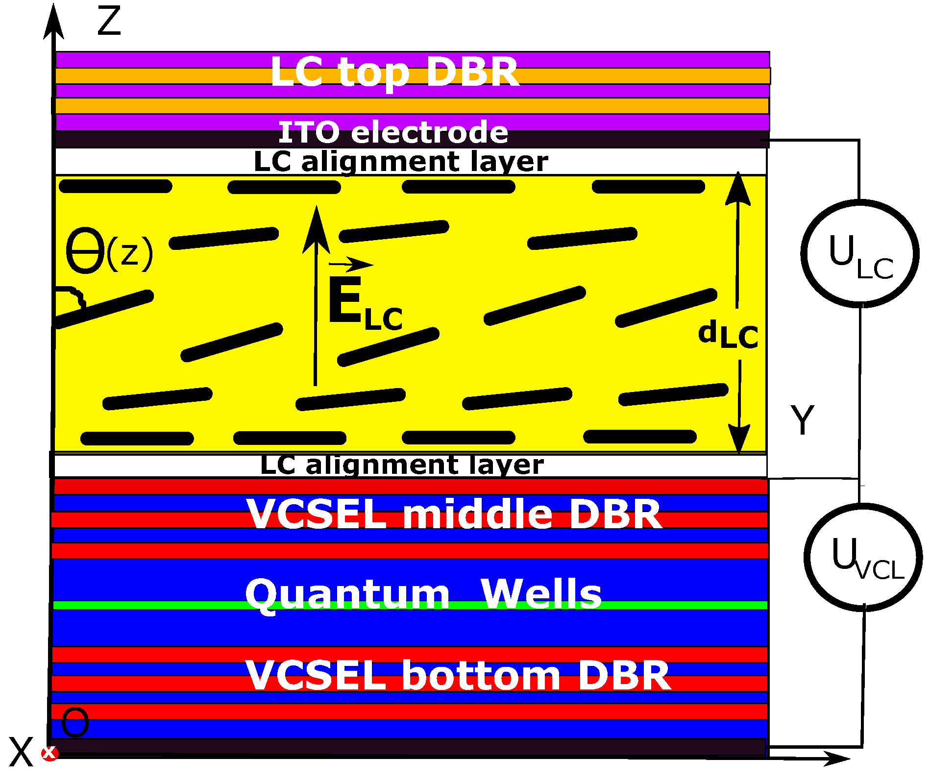
2.1. VCSEL with a Liquid Crystal: Schematic and Exemplary Structure

The intra-cavity LC-VCSEL system is schematically shown in Figure 1. An electrical field is applied to the nematic LC layer along the direction of light emission ( E L C O z ) by means of the indium-tin oxide (ITO) electrodes deposited on the top side of the VCSEL active chip (VCSEL middle Distributed Bragg Reflector (DBR) in Figure 1) and on the bottom side of the top dielectric DBR [19,20]. The planar alignment of the nematic LC molecules at the boundaries of the LC layer (the longer axis of the LC molecules oriented along the O y axis) is achieved by the two photo-alignment layers as depicted in Figure 1. The electrical field E L C applied to the LC cell will turn the LC director (the averaged direction of the longer axis of the LC molecules) at an angle θ ( z ) , which depends on the distance z to the anchoring boundary x O y [15].

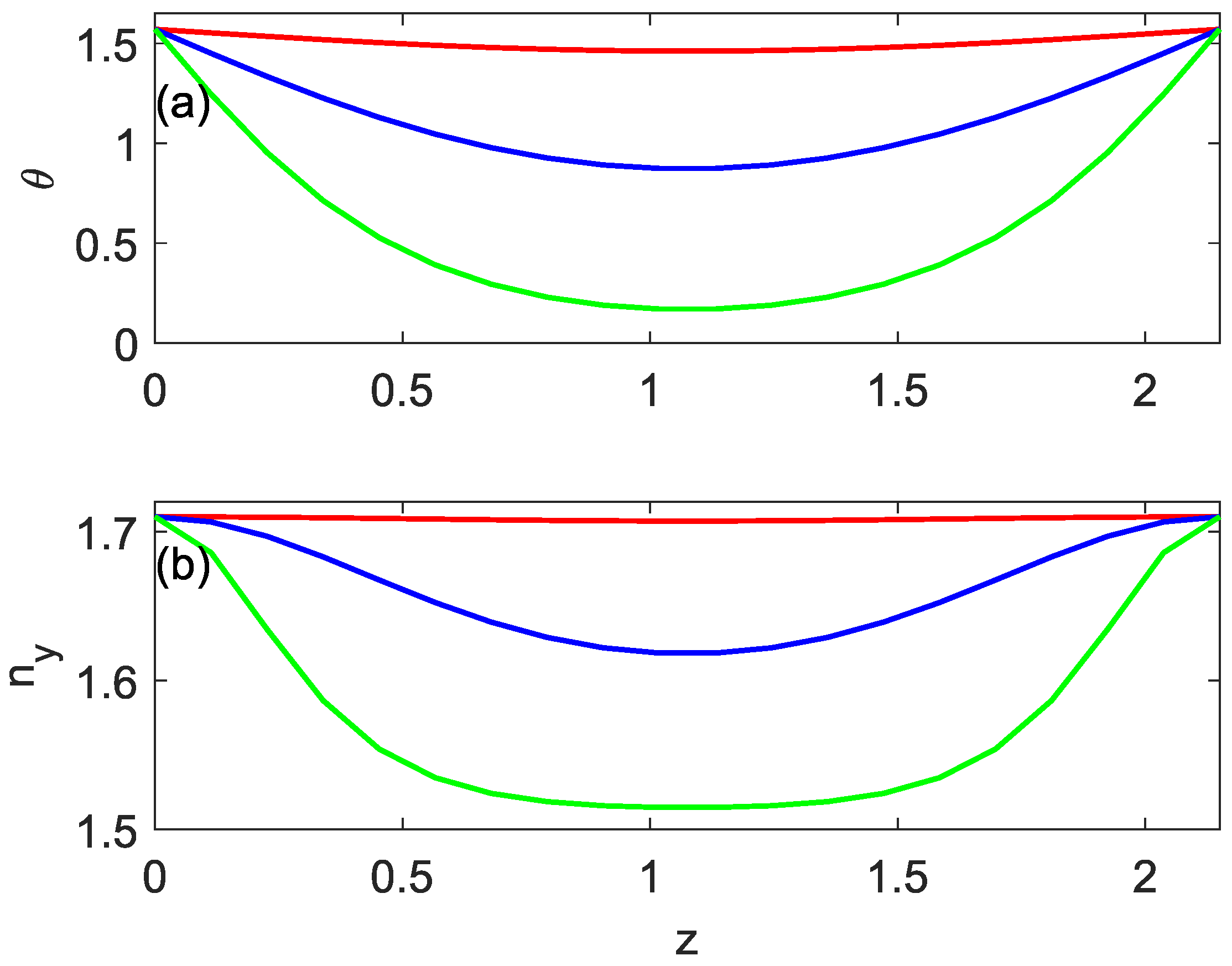
2.2. Electo-Optic Effect in the Liquid-Crystal Layer

First, we consider the LC cavity alone. As denoted schematically in Figure 1, the orientation of the LC director (the angle θ ) depends on the distance z to the anchoring boundary x O y . In order to estimate this dependence, we apply the one-elastic-constant approximation [15] for the LC layer with hard boundary conditions with planar alignment, i.e., θ ( 0 ) = θ ( d L C ) = π / 2
K d 2 θ d z 2 + Δ ϵ 4 π E 2 sin θ cos θ = 0 .
Here, K is the elastic constant, E = U L C / d L C is the electric field applied to the LC layer with U L C being the applied voltage, d L C is the LC layer thickness and Δ ϵ is the dielectric anisotropy given by Δ ϵ = ϵ | | ϵ .
Figure 2a presents the distribution of the LC director orientation along an LC cell with thickness d L C = 3.2 μ m for different values of the applied voltage. When solving the boundary value problem as defined by Equation (1), we used for concreteness the parameter values for E 7 liquid crystal, namely K = 3 × 10 12 N and Δ ϵ = 13.8 (see page 314 of ref. [15] and [31]).
In the nematic LC-VCSELs as depicted in Figure 1, the refractive indices for light travelling along the O z axis and linearly polarized along the O x and O y axes read, respectively:
n x = n o , n y = n o n e n o 2 s i n 2 ( θ ( z ) ) + n e 2 c o s 2 ( θ ( z ) ) .
Here, n o and n e are the LC ordinary and extraordinary refractive indices. Equation (2) shows that the electro-optically induced LC director reorientation θ ( z ) directly translates in refractive index distribution for light linearly polarized in the O y direction. Figure 2b presents the distribution of the refractive index n y ( z ) along the LC cell for the same values applied to the LC voltage U L C as the ones used for the calculation of the LC director orientation in Figure 2a.

2.3. Modal Properties of Liquid-Crystal VCSEL System

The LC-VCSEL structure as schematically depicted in Figure 1 is generic and could be utilized for lasers with different semiconductor material composition, providing lasing at different wavelengths. Here, we consider for concreteness a GaAs quantum well (QW) LC-VCSEL lasing around 850 nm. The semiconductor multilayer structure suggested in this paper and the LC parameters are listed in Table 1. For simplicity and easier reproducibility, the spectral dependencies of the complex refractive indices of the different materials comprising the LC-VCSEL are not taken into account; considering material dispersion does not change the basic results of this study. As demonstrated in [19,25], the part of the optical field residing in the LC cavity strongly depends on the thickness of the LC layer and the presence and the strength of the middle VCSEL DBR. The strongest impact of the LC on the LC-VCSEL properties is achieved when the middle DBR is completely omitted (c.f. [25,26,27] for the optimization of wavelength tuning region of intracavity LC-VCSELs). In our case, however, such an intracavity LC-VCSEL is very sensitive to LC voltage change. Therefore, we chose to keep in this study a part of the VCSEL top DBR to serve as a middle DBR of the LC-VCSELs and to provide both wide enough tuning range and good tuning sensitivity of the LC-VCSEL birefringence.
Our procedure for finding the longitudinal resonant wavelength of the LC-VCSEL and the confinement factors in the active QW region and the LC layer is based on the transfer matrix method. An implicit characteristic equation is obtained by imposing the condition that there is no incoming field for the whole LC-VCSEL multilayer structure [32]. The complex implicit characteristic equation is then solved for two variables, namely the resonant wavelength λ r e s and the imaginary part of the quantum well refractive index n Q W i m [32]. Finally, the field distribution along the longitudinal z-direction of the LC-VCSEL and, consequently, the confinement factors in the QW and LC regions are obtained. In order to tackle the inhomogeneous distribution of the refractive index in the LC layer for light linearly polarized along the O y -direction as illustrated in Figure 2, we divide the LC layer into a number of thin layers with uniform refractive index distribution.
Figure 3 presents the optical power distribution calculated in such a way for two resonant modes of the LC-VCSEL for light linearly polarized along the O x (Figure 3a) and O y (Figure 3b) directions and when the LC is biased by a voltage of U L C = 0.56 V . In Figure 3a, the ordinary refractive index n x of the LC layer is not impacted by the LC electro-optical effect and refractive index distribution n x ( z ) = c o n s t = n o is uniform. As can be seen, a significant part of the optical field resides in the LC cavity, which reduces the part residing in the QW active region and, therefore, diminishes the QW confinement factor (see also next section). For light polarized in the O y direction, the LC director reorientation caused by the applied voltage leads to nonuniform distribution of the LC refractive index n y ( z ) along the LC cavity, slightly diminished from the 0-voltage value of n y ( 0 V ) = n e . For this case, the part of the optical field that resides in the LC cavity is significantly decreased, which brings a higher QW confinement factor.

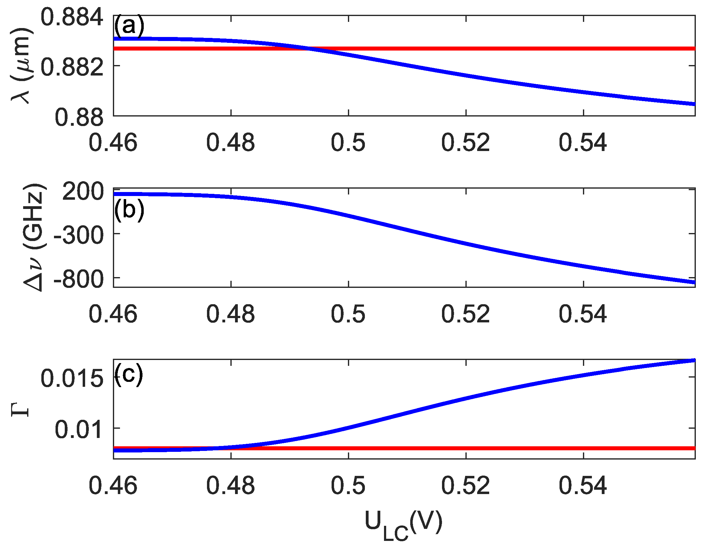
2.4. Electro-Optical Tuning of the Birefringence of the LC-VCSEL System

When the voltage applied to the LC layer in the LC-VCSEL is changed, the refractive index n y is changed and, consequently, the optical field distribution, the resonant wavelength and the QW confinement factors are modified, too. This is illustrated in Figure 4 for the LC-VCSEL considered so far: Figure 4a represents the resonant wavelengths for light polarized along O x (red line) and along O y (blue line) directions as a function of the voltage U L C applied to the LC layer; Figure 4b is the same but expressed as frequency splitting and Figure 4c shows the corresponding confinement factors in the active QW layer. As can be seen, a change in the LC voltage of about 0.1 V changes the frequency splitting from positive (about 200 GHz) to negative (about −800 GHz), i.e., a change as large as 1000 GHz. At the same time, the QW confinement factor for the y-polarized mode increases about two times. We would like to stress that these electro-optically induced changes, i.e., the voltage sensitivity of the LC-VCSEL is a matter of LC-VCSEL design—it can be easily controlled by altering the coupling between the VCSEL cavity containing the QWs and the LC cavity. This can be done by either modifying the number of quarter-wavelength layers in the middle DBR or the ratio of the optical thicknesses of the two cavities.
Next, we investigate the impact of the electro-optically induced frequency tuning of the LC-VCSEL on its modulation characteristics.

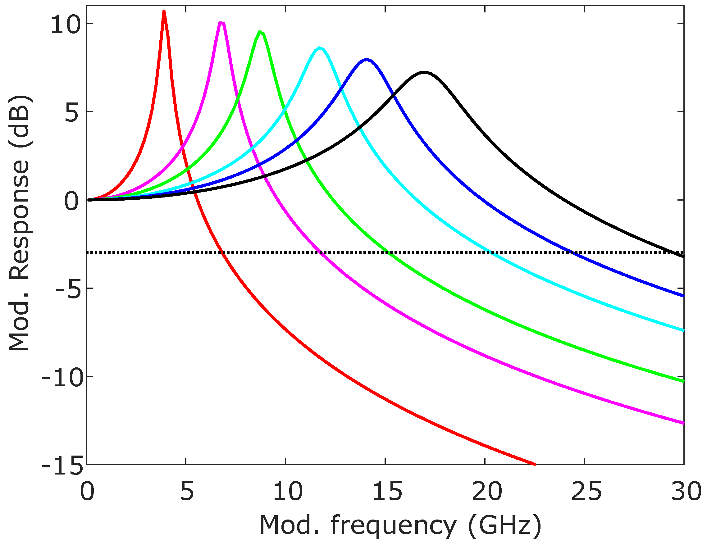
3. Modulation Characteristics of LC-Spin-VCSEL: Electro-Optical Tuning

The Spin-Flip Model (SFM) describing spin-VCSELs reads [4]
d E x d t = κ 1 + i α N E x + i n E y E x i γ p E x γ a E x ,
d E y d t = κ 1 + i α N E y i n E x E y + i γ p E y + γ a E y ,
d N d t = γ e ( μ + + μ ) γ e N 1 + E x 2 + E y 2 i γ e n E y E x * E x E y * ,
d n d t = γ e ( μ + μ ) γ s n γ e n E x 2 + E y 2 i γ e N E y E x * E x E y * .
The SFM is included here for the slowly varying electric field amplitudes E x and E y of light linearly polarized in the x and y directions, respectively [5]. The carrier variables N and n are related to, respectively, the total inversion between conduction and heavy-hole valence bands and the difference in the carrier numbers of the two sublevels with opposite spins [4]. Amplitude anisotropy is modelled through linear dichroism γ a and phase anisotropy is modelled by the linear birefringence γ p [5]. The other internal VCSEL parameters are defined as follows: κ is the optical field decay rate, γ e is the decay rate of N, γ s is the spin-flip relaxation rate, α is the linewidth enhancement factor. Electrical andor optical spin dependent pumping is represented by μ + and μ terms corresponding to the spin-up and spin-down carriers, respectively, i.e., μ = μ + + μ is the total injected carrier density and P is the polarization degree of the injected carriers, namely
P = μ + μ μ + + μ .
It is implicitly accepted in the SFM that the modal gains of the two linearly polarized VCSEL modes are equal. As we have seen in the previous section, however, the longitudinal confinement factors for the two orthogonally polarized fields can be significantly different in the LC-VCSELs considered here. In order to take this into account, we consider the normalization used in the SFM, namely E = G n / γ E ˜ and N = G n ( N ˜ N ˜ t r ) / ( 2 κ ) with κ = 1 / ( 2 τ p ) with τ p being the photon lifetime. Here, E ˜ , N ˜ and N ˜ t r are the non-normalized electric field, carrier density and carrier density at transparency, and G n is the coefficient in the linear dependence of the gain on carrier density. We also consider the case of one dominant polarization and no anisotropies and spin-flip effects, i.e., E y = n = γ p = γ a = 0 and γ s = leading to
d E ˜ x d t = 1 2 1 + i α G n ( N ˜ N ˜ t r ) 1 τ p E ˜ x .
Infinite spin-flip relaxation rate is the typical assumption when considering rate equations for semiconductor lasers (c.f. [33]) as normally it is much larger than the relaxation rates of optical field and carriers. From Equation (8), the rate equation for the photon density N p h , x = E x E x * becomes
d N p h , x d t = G n ( N ˜ N ˜ t r ) 1 τ p N p h , x .
Comparing this equation with the usual semiconductor rate equations as derived in, e.g., [33]
d N p h d t = Γ v g g n ( N N t r ) 1 τ p N p h
and introducing an average Γ = ( Γ x + Γ y ) / 2 and a relative difference δ Γ = ( Γ x Γ y ) / 2 of the confinement factors for the two linearly polarized fields, namely Γ x , y = Γ ( 1 ± δ Γ / Γ ) , we obtain for the intensities of the orthogonally polarized modes
d N p h , x , y d t = G n 1 ± δ Γ Γ ( N ˜ N ˜ t r ) 1 τ p N p h , x , y
with G n = Γ v g g n . Therefore, the SFM becomes slightly modified for the case of polarization dependent confinement factors as in LC-VCSELs, namely
d E x d t = κ 1 + i α I + ( N E x + i n E y ) E x i γ p E x γ a E x ,
d E y d t = κ 1 + i α I ( N E y i n E x ) E y + i γ p E y + γ a E y ,
d N d t = γ e μ γ e N 1 + E x 2 + E y 2 i γ e n E y E x * E x E y * ,
d n d t = γ e P μ γ s n γ e n E x 2 + E y 2 i γ e N E y E x * E x E y * ,
where we defined I ± = 1 ± δ Γ Γ .
We perform the numerical simulations in the rest of the paper using this slightly modified SFM, Equations (12)–(15). Applying the methodology outlined in the previous Section 2, we first calculate the LC-VCSEL resonant wavelengths and QW confinement factors of the longitudinal modes linearly polarized in the x and y directions for a given voltage applied to the LC. Then, we solve the LC-VCSEL rate equations using the so-calculated γ p , I + and I and the following parameters for the VCSEL: κ = 300 ns 1 , α = 3 , γ e = 1 ns 1 , γ a = 0 ns 1 and for two values of the spin-flip relaxation rate: γ s = 300 ns 1 and γ s = 600 ns 1 .
First, we consider the case of a small signal intensity modulation, i.e., P = 0 and
μ = μ 0 ± Δ μ × sin ( 2 π f t ) ,
where μ 0 is a constant; Δ μ —the modulation amplitude; f—the modulation frequency. Figure 5 shows the small signal modulation response for a total injection modulation according to Equation (16) and for different values of injection current. The voltage applied to the LC is fixed to U L C = 0.465 V, providing a phase anisotropy of γ p = 468 ns 1 . As typical for class B semiconductor lasers, the modulation bandwidth is limited by the relaxation oscillation frequency, i.e., the frequency of periodic energy exchange between carrier and photon reservoirs. The intensity modulation response depends on the confinement factor and we observe an increase of several GHz for the position of its maximum when the confinement factor is increased via the LC voltage as shown in Figure 4c. Despite the increase in the relaxation frequency with the injection current as evident in Figure 5, even for a very strong injection of μ = 20 the small signal modulation bandwidth does not exceed 30 GHz (the relaxation frequency is about 17 GHz in this case). One way to overcome this relaxation oscillation limitation of modulation bandwidth is by spin-injection modulation as shown in [13].
Therefore, we consider as a second case LC-VCSEL polarization modulation according to
P = P 0 + Δ P × sin ( 2 π f t ) ,
with P 0 being a constant and Δ P being the modulation amplitude. Figure 6 shows the small signal polarization modulation response, i.e., when only the spin injection is modulated according to Equation (17) and for different voltages applied to the LC layer leading to different LC-induced birefringence ranging from γ p = 468 ns 1 downto γ p = 7.5 ns 1 and then to γ p = 1610 ns 1 . Two cases are considered: γ s = 300 ns 1 (Figure 6a) and γ s = 600 ns 1 (Figure 6b). Now, the peak in the modulation response is determined by the birefringence of the LC-VCSEL, i.e., by the beating frequency between the x and y polarization modes and the relaxation oscillation peak characteristic for intensity modulation (c.f. Figure 5) is not visible as the total injection current μ is not modulated. The 3 dB cut off frequency of small signal modulation can be therefore drastically increased, reaching values as high as several hundred GHz. The modulation peak amplitudes for positive birefringence (coloured curves) are higher than the ones for negative birefringence (black curves) which we attribute to the fact that when changing the LC voltage, together with the change in the frequency splitting between the two orthogonally polarized LC-VCSEL modes, the confinement factor for the y-polarized mode is also changed. This directly impacts the shape of the small signal modulation response. For example, for γ p = 310 GHz at U L C = 0.483 V , the confinement factor for the y-polarized mode is Γ y = 0.0083 , while for γ p = 306 GHz at U L C = 0.5 V the confinement factor is Γ y = 0.01 . For a very large birefringence, especially for the black curves in Figure 6a, the 3 dB cut off frequency is limited by the pronounced dip between the zero-frequency response and the peak of the modulation characteristics. It has been noted in [34] that this dip can be lifted for a higher spin-flip relaxation rate. Indeed, the limitation due to the dip in the small signal modulation response is avoided in Figure 6b calculated for γ s = 600 ns 1 and a cut off frequency as high as 400 GHz is achieved.

4. Conclusions

We suggest in this paper a VCSEL device with embedded nematic liquid crystal (LC) second cavity. We design such an exemplary coupled-cavity LC-VCSEL and develop a procedure for calculating its LC-voltage dependent polarization resolved resonant longitudinal modes and their QW confinement factors. Using these characteristics of the LC-VCSEL, we are able to slightly modify the spin-flip VCSEL model to include the voltage dependent birefringence and anisotropy due to the different QW confinement factors for the two orthogonal linearly polarized LC-VCSEL modes. We show that the large electro-optical effect in the LC makes it possible to introduce large voltage-controlled birefringence for the whole LC-VCSEL device. Finally, we consider small signal polarization modulation, i.e., when only the carrier-spin injection is modulated while the total carrier injection is kept constant, and demonstrate the small signal modulation response of the LC-VCSEL with a 3 dB cut off frequency of several hundreds of GHz.

Author Contributions

Conceptualization and validation, K.P.; methodology, writing—review and editing, K.P., M.P. and Y.M. All authors have read and agreed to the published version of the manuscript.

Funding

The authors acknowledge the financial support by the National Science Fund (NSF) of Bulgaria contract № KP-06-N58/6 from 19.11.2021 granted under “Competition for financing fundamental scientific research—2021”.

Data Availability Statement

Data is contained within the article.

Conflicts of Interest

The authors declare no conflict of interest.

Abbreviations

The following abbreviations are used in this manuscript:
MDPIMultidisciplinary Digital Publishing Institute
VCSELsVertical-Cavity Surface-Emitting Lasers
QWQuantum Well
LCLiquid Crystal
SFMSpin-Flip Model

References

  1. Holub, M.; Bhattacharya, P. Spin-polarized light-emitting diodes and lasers. J. Phys. D Appl. Phys. 2007, 40, R179–R203. [Google Scholar] [CrossRef]
  2. Pusch, T.; Scherbl, S.; Lindemann, M.; Gerhardt, N.C.; Hofmann, M.R.; Michalzik, R. Spin Lasers for Optical Data Communication in Semiconductor Lasers and Laser Dynamics VIII, 10682; Panajotov, K., Sciamanna, M., Michalzik, R., Eds.; Proceedings SPIE; SPIE Press: Washington, DC, USA, 2018; pp. 120–125. [Google Scholar]
  3. Žutić, I.; Xu, G.; Lindemann, M.; Faria, P.E.; Lee, J.; Labinac, V.; Stojisic, K.; Sipahi, G.M.; Hofmann, M.R.; Gerhardt, N.C. Spin-Lasers: Spintronics Beyond Magnetoresistance. Solid State Commun. 2020, 316–317, 113949. [Google Scholar] [CrossRef]
  4. Miguel, M.S.; Feng, Q.; Moloney, J.V. Light-polarization dynamics in surface-emitting semiconductor lasers. Phys. Rev. A 1995, 52, 1728–1739. [Google Scholar]
  5. Martın-Regalado, J.M.; Prati, F.; SanMiguel, M.; Abraham, N.B. Polarization properties of vertical cavity surface-emitting lasers. IEEE J. Quantum Electron. 1997, 33, 765–783. [Google Scholar]
  6. Chang-Hasnain, C.J.; Harbison, J.P.; Hasnain, G.; Lehmen, A.C.V.; Florez, L.T.; Stoffel, N.G. Polarization and transverse mode characteristics of vertical-cavity surface-emitting lasers. IEEE J. Quantum Electron. 1991, 27, 1402–1408. [Google Scholar]
  7. Choquette, K.D.; Schneider, R.P.; Lear, K.L.; Leibenguth, R.E. Gain dependent polarization properties of vertical-cavity lasers. IEEE J. Sel. Top. Quantum Electron. 1995, 1, 661–666. [Google Scholar]
  8. Panajotov, K.; Sciamanna, M.; Arizaleta, M.; Thienpont, H. Optical Feedback in Vertical-Cavity Surface-Emitting Lasers. IEEE J. Sel. Top. Quantum Electron. 2013, 19, 1700312. [Google Scholar] [CrossRef]
  9. Panajotov, K.; Prati, F. Polarization Dynamics of VCSELs. In VCSELs; Michalzik, R., Ed.; Springer Series in Optical Sciences; Springer: Berlin/Heidelberg, Germany, 2012; Volume 166. [Google Scholar]
  10. Virte, M.; Panajotov, K.; Thienpont, H.; Sciamanna, M. Deterministic polarization chaos from a laser diode. Nat. Photonics 2012, 7, 60–65. [Google Scholar] [CrossRef]
  11. Rudolph, J.; Döhrmann, S.; Hägele, D.; Oestreich, M.; Stolz, W. Room-temperature threshold reduction in vertical-cavity surface-emitting lasers by injection of spin-polarized electrons. Appl. Phys. Lett. 2005, 87, 241117. [Google Scholar]
  12. Holub, M.; Shin, J.; Bhattacharya, P. Electrical spin injection and threshold reduction in a semiconductor laser. Phys. Rev. Lett. 2007, 98, 146603. [Google Scholar]
  13. Lindemann, M.; Xu, G.; Pusch, T.; Michalzik, R.; Hofmann, M.R.; Žutić, I.; Gerhardt, N.C. Ultrafast spin-lasers. Nature 2019, 568, 212–215. [Google Scholar] [CrossRef] [PubMed]
  14. Panajotov, K.; Nagler, B.; Verschaffelt, G.; Georgievski, A.; Thienpont, H.; Danckaert, J.; Veretennicoff, I. Impact of in-plane anisotropic strain on the polarization behaviour of vertical-cavity surface-emitting lasers. Appl. Phys. Lett. 2000, 77, 1590–1592. [Google Scholar] [CrossRef]
  15. Khoo, I.-C. Liquid Crystals, 2nd ed.; Wiley: New York, NY, USA, 2007; pp. 58–61. [Google Scholar]
  16. Andrews, J.R. Low voltage wavelength tuning of an external cavity diode laser using a nematic liquid crystal-containing birefringent filter. IEEE Photon. Technol. Lett. 1990, 2, 334–336. [Google Scholar]
  17. Merlier, J.D.; Mizutani, K.; Sudo, S.; Naniwae, K.; Furushima, Y.; Sato, S.; Sato, K.; Kudo, K. Full C-band external cavity wavelength tunable laser using a liquid-crystal-based tunable mirror. IEEE Photon. Technol. Lett. 2005, 17, 681–683. [Google Scholar]
  18. Wilkinson, C.I.; Woodhead, J.; Frost, J.E.F.; Roberts, J.S.; Wilson, R.; Lewis, M.F. Electrical polarization control of vertical-cavity surface-emitting lasers using polarized feedback and a liquid crystal. IEEE Photon. Technol. Lett. 1999, 11, 155–157. [Google Scholar]
  19. Panajotov, K.; Thienpont, H. Vertical-cavity surface-emitting laser with liquid crystal overlay. Opt. Express 2011, 19, 16749–16759. [Google Scholar] [CrossRef]
  20. Xie, Y.; Beeckman, J.; Woestenborghs, W.; Panajotov, K.; Neyts, K. VCSEL With Photo-Aligned Liquid Crystal Overlay. IEEE Phot. Technol. Lett. 2012, 24, 1509–1512. [Google Scholar]
  21. Xie, Y.; Beeckman, J.; Panajotov, K.; Neyts, K. Vertical-Cavity Surface-Emitting Laser With a Liquid Crystal External Cavity. Opt. Lett. 2014, 39, 6494–6497. [Google Scholar]
  22. Panajotov, K.; Xie, Y.; Dems, M.; Belmonte, C.; Thienpont, H.; Beeckman, J.; Neyts, K. Vertical-cavity surface-emitting laser emitting circularly polarized light. Laser Phys. Lett. 2013, 10, 105003. [Google Scholar] [CrossRef]
  23. Xie, Y.; Beeckman, J.; Panajotov, K.; Neyts, K. Vertical-Cavity Surface-Emitting Laser With a Chiral Nematic Liquid Crystal Overlay. IEEE Photonics J. 2014, 6, 1500010. [Google Scholar]
  24. Wilkinson, C.I.; Woodhead, J.; Frost, J.E.F.; Roberts, J.S.; Wilson, R.; Lewis, M.F. Enhancement of a liquid-crystal modulator using an external-cavity VCSEL. IEEE Photon. Technol. Lett. 1999, 11, 940–942. [Google Scholar]
  25. Belmonte, C.; Frasunkiewicz, L.; Czyszanowski, T.; Thienpont, H.; Beeckman, J.; Neyts, K.; Panajotov, K. Optimization of electrically tunable VCSEL with intracavity nematic liquid crystal. Opt. Express 2015, 23, 15706. [Google Scholar] [CrossRef] [PubMed]
  26. Frasunkiewicz, L.; Czyszanowski, T.; Thienpont, H.; Panajotov, K. Polarization- and Modal-Control in a Vertical-Cavity Surface-Emitting Laser With an External-Cavity Formed by a Liquid Crystal Overlay. J. Light. Technol. 2016, 34, 5437. [Google Scholar] [CrossRef]
  27. Frasunkiewicz, L.; Czyszanowski, T.; Thienpont, H.; Panajotov, K. Electrically tunable VCSEL with intra-cavity liquid crystal: Design, optimization and analysis of polarization- and mode-stability. Opt. Commun. 2018, 427, 271. [Google Scholar]
  28. Debernardi, P.; Simaz, A.; Tibaldi, A.; Boisnard, B.; Camps, T.; Bertazzi, F.; Goano, M.; Reig, B.; Doucet, J.-B.; Bardinal, V. Anisotropic Transverse Confinement Design for Electrically Pumped 850 nm VCSELs Tuned by an Intra Cavity Liquid-Crystal Cell. IEEE J. Sel. Top. Quantum Electron. 2022, 28, 1700111. [Google Scholar] [CrossRef]
  29. Castany, O.; Dupont, L.; Shuaib, A.; Gauthier, J.P.; Levallois, C.; Paranthoën, C. Tunable semiconductor vertical-cavity surface-emitting laser with an intracavity liquid crystal layer. Appl. Phys. Lett. 2011, 98, 161105. [Google Scholar]
  30. Sadani, B.; Boisnard, B.; Lafosse, X.; Camps, T.; Doucet, J.B.; Daran, E.; Paranthoen, C.; Levallois, C.; Dupont, L.; Bouchoule, S.; et al. Liquid-Crystal alignment by a nanoimprinted grating for wafer-scale fabrication of tunable devices. IEEE Photonics Technol. Lett. 2018, 30, 1388. [Google Scholar]
  31. Tkachenko, V.; Dyomin, A.A.; Tkachenko, G.V.; Abbate1, G.; Sukhoivanov, I.A. Electrical reorientation of liquid crystal molecules inside cylindrical pores for photonic device applications. J. Opt. A Pure Appl. Opt. 2008, 10, 055301. [Google Scholar]
  32. Panajotov, K.; Zujewski, M.; Thienpont, H. Coupled-cavity surface-emitting lasers: Spectral and polarization threshold characteristics and electrooptic switching. Opt. Exp. 2010, 18, 27525. [Google Scholar]
  33. Coldren, L.A.; Corzine, S.W. Diode Lasers and Photonic Integrated Circuits; Wiley: New York, NY, USA, 1995. [Google Scholar]
  34. Huang, Y.; Zhou, P.; Torre, M.; Li, N.; Henning, I.; Adams, M. Optically Pumped Spin-VCSELs: Toward High-Frequency Polarization Oscillations and Modulation. IEEE J. Quantum Electron. 2021, 57, 2400212. [Google Scholar]
Figure 1. VCSEL with a liquid crystal: an electric field is applied to the liquid crystal layer along the direction of light emission ( E L C O z ). Planar alignment of the LC molecules close to the LC boundaries is along the O y axis ensured by the two photo-alignment layers.
Photonics 10 00179 g001
Figure 2. Distribution along an LC cell (along the O z axis) of (a) LC director angle θ and (b) LC refractive index n y for light linearly polarized along the O y direction. The thickness of the LC layer is d L C = 2.15 μ m. The voltage applied to the LC cell is: U L C = 0.48 V (red curves), U L C = 0.56 V (blue curves) and U L C = 1 V (green curves). The parameter values for E 7 liquid crystal used for solving Equation (1) are K = 3 × 10 12 N and Δ ϵ = 13.8 .
Photonics 10 00179 g002
Figure 3. Optical power | E ( z ) | 2 distribution along the O z axis of the LC-VCSEL resonant modes linearly polarized along the O x (a) and along the O y (b) direction. The voltage applied to the LC is U L C = 0.56 V . The black curves represent the refractive index distribution along the LC-VCSEL for the respective light polarizations.
Photonics 10 00179 g003
Figure 4. Dependences on the voltage U L C applied to the LC of: (a) Wavelengths of the LC-VCSEL resonant longitudinal modes polarized along O x (red lines) and along O y (blue lines); (b) Difference between the frequencies of these resonant modes and (c) QW confinement factors of these resonant modes.
Photonics 10 00179 g004
Figure 5. Small signal modulation response for a total injection modulation according to Equation (16) and for different bias injection levels: μ = 2 —red line; μ = 4 —magenta line; μ = 6 —green line; μ = 10 —cyan line; μ = 14 —blue line; and μ = 20 —black line. The straight dotted line shows the level of −3 dB.
Photonics 10 00179 g005
Figure 6. Small signal polarization modulation response for spin injection modulation of the LC-VCSEL according to Equation (17) and for different LC-voltage: U = 0.493 V ( γ p = 7.5 GHz )—blue color; U = 0.49 V ( γ p = 116 GHz )—cyan color; U = 0.487 V ( γ p = 211 GHz )—magenta color; U = 0.483 V = ( γ p = 310 GHz )—green color; U = 0.477 V ( γ p = 404 GHz )—yellow color; U = 0.465 ( γ p = 468 GHz )—red color. The black color curves correspond to (from left to right) U = 0.506 V ( γ p = 607 GHz), U = 0.51 V ( γ p = 811 GHz), U = 0.514 V = ( γ p = 1012 GHz), U = 0.519 V ( γ p = 1253 GHz), U = 0.527 V ( γ p = 1610 GHz). The straight dotted lines show the level of −3 dB. The spin-flip relaxation rate is (a) γ s = 300 GHz and (b) γ s = 600 GHz.
Photonics 10 00179 g006
Table 1. VCSEL and LC parameters.
VCSEL: Bottom/Middle DBR: 37.5 / 11.5 Pairs
MaterialRefr. IndexThickness ( μ m)
A l 0.12 G a 0.88 A s 3.52 i 10 4 0.0603
A l 0.9 G a 0.2 A s 3.11 i 10 4 0.0683
VCSEL λ cavity
A l 0.3 G a 0.7 A s 3.4 i 10 4 0.133
3 G a A s Q W 3.62 + i * n i m Q W 0.024
A l 0.3 G a 0.7 A s 3.4 i 10 4 0.133
LC and ITO
E7 n o = 1.51 2.15
n e = 1.71
photoalignment layer 1.8 i 0.03 0.01
ITO 1.76 i 0.08 0.1
LC dielectric mirror N L C = 2.5 pairs
T i O 2 2.490.0853
S i O 2 1.530.1389
Disclaimer/Publisher’s Note: The statements, opinions and data contained in all publications are solely those of the individual author(s) and contributor(s) and not of MDPI and/or the editor(s). MDPI and/or the editor(s) disclaim responsibility for any injury to people or property resulting from any ideas, methods, instructions or products referred to in the content.

