1. Introduction
Ultra-short laser pulses have many advantages, such as high peak power [
1], broadband spectrum and short duration [
2], which have a bright and broad application prospect in the fields of micromachining [
3], huge-capacity communication and biomedicine [
4,
5]. Compared with solid pulsed lasers, fiber lasers have many advantages such as low cost [
6], excellent cooling effect, good environment stability [
6] and so on. Early studies were carried out with anomalous dispersion fiber lasers, and traditional solitons have always been achieved based on the balance between the dispersion and the nonlinearity [
7,
8]. As it turns out, stable pulses could also be obtained in the all-normal dispersion fiber lasers involving filters [
9]. The pulses are broadened as they circulate in the cavity, and the saturable absorber and filter reshape the pulse to its original shape in both the time and frequency domains [
9]. Pulse formation results from the combination interaction of dispersion and nonlinearity, gain and loss, filter-induced spectral narrowing and fiber nonlinearity-induced spectral broadening [
10]. Pulse peak power is reduced while the pulse is broadened in the normal-dispersion fiber, which diminishes the impact of fiber nonlinearity. Thus, stable pulses with high energy have been obtained in these fiber lasers [
9].
One of the most important elements in normal-dispersion mode-locked fiber lasers is the filter, which shapes the pulse by cutting the edges of the spectrum in the frequency domain [
1,
11]. To date, both birefringent quartz slice and diffraction grating [
11] have been used as filters to obtain stable pulses in normal-dispersion fiber lasers. However, the use of discrete elements complicates the laser construction. Fiber gratings could provide the all-fiber structure; however, the bandwidths of fiber gratings are normally lower than 5 nm. Another type of widely used filter is the comb filter exploiting mode interference effect [
12], which is usually based on an interferometer, such as the Fabry–Perot, Sagnac or Mach–Zehnder interferometers (MZI). These filters have the advantages of simple structure, low cost, and an easy-to-fabricate all-fiber structure. MZI filters have been reported based on two 3 dB optical couplers [
13,
14]. By inserting the filter into one fiber laser mode-locked by nonlinear polarization rotation, stable dissipative solitons have been obtained [
14]. The structure of this filter is simple; however, it is accompanied by the disadvantages of insufficient compactness, inconducive to integration and the optical path difference between these two paths is not easy to control preciously. The interference filter could also be fabricated by splicing one segment of tapered seven-core fiber (SCF) between two segments of single-mode fibers [
15]. Inserting these all-fiber MZI filters with different free space range (FSR) in an Yb-doped mode-locked fiber laser, wavelength-tunable dissipative solitons and amplifier similaritons have been obtained. However, tapering reduces the stability of optical fiber, and the taper process requires expensive equipment.
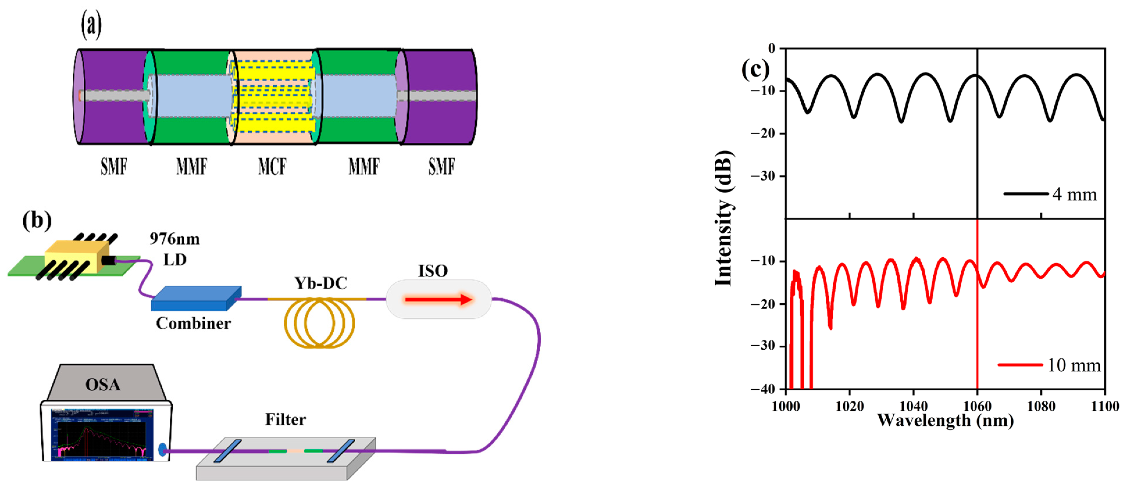
In this paper, an interference filter is fabricated by fusing two segments of multimode fibers (MMFs) and one segment of a multi-core fiber (MCF) sequentially between two segments of single-mode fibers (SMFs). The FSR of the transmissivity curve, and thus the bandwidth of the filter, is related to the length of MCF. When the lengths of MCF are selected to be 4 mm and 10 mm, the FSR of the transmissivity curve around 1060 nm is 15.44 nm and 8.60 nm, respectively, and the 3 dB bandwidths of filters are 8.40 nm and 4.84 nm, respectively. By applying both of these two filters in an Yb-doped fiber laser, stable pulses have been obtained.
2. Operation Principle of the Interference Filter
Figure 1a shows the structure of the fabricated interference filter. Two sections of MMFs and one section of MCF are spliced sequentially between two sections of SMFs using an optical fiber fusion splicer. The SMF has a core diameter of 5.3 μm and a cladding diameter of 125 μm. The core and cladding diameters of the MMF are 50 μm and 125 μm, respectively. The MCF contains seven cores, with one core located in the middle of the fiber and the other six cores symmetrically distributed around it. The core diameter is ~6.1 μm and the distance between two cores is ~35 μm. The two segments of MMFs function as optical couplers to couple light to the cladding and different cores of the MCF and collect light from the multi-core fiber. The lengths of the two MMFs are chosen to be ~10 mm.
When the light propagating in the SMF is injected into the first segment of MMF, multiple high-order guiding modes are excited due to the mode–field mismatch. The MMF couples the light into the cores and cladding of the MCF, which is then coupled back to the SMF by the second segment of MMF. The light propagating in the cores and cladding of the MCF experience a different optical path, so they interfere with each other in the following SMF. The transmissivity of the interference filter can be expressed as
where
and
are the light intensity of the core mode and cladding mode propagating in the MCF, respectively. The phase difference between these modes can be expressed as
where
is the length of the MCF fiber,
is the effective refractive index difference between the cladding and the core of the MCF, and
is the wavelength of the propagating light in the fiber [
16]. When the phase difference
θ = 2
nπ, the resonant peak wavelength of the transmission spectrum can be deduced from Equation (2), which is expressed as
where
denotes the wavelength of the nth-order resonance peak. The ambient refractive index of the fusion spliced multi-core fiber is usually constant, so changing the length of the MCF will cause
to drift. The FSR of the interference curve can be written as
Therefore, it is clear from the above equation that the FSR increases with the decrease in the length of MCF (
) [
17,
18]. The bandwidth of the filter relates to the FSR of the transmissivity curve, which increases with the decrease in
simultaneously.
The transmission characteristic of the interference filter is measured using a homemade amplified spontaneous emission (ASE) light source, as shown in
Figure 1b. An OSA (Optical Spectrum Analyzer, AQ 6374) is used to collect the light from the interference filter.
Figure 1c shows the transmission spectra of the interference filter. When the length of the MCF is chosen to be 4 mm, the FSR around 1060 nm of the upper transmissivity curve in
Figure 1c is estimated to be 15.44 nm, with a 3 dB bandwidth of 8.40 nm. When the length of the MCF is selected as 10 mm in the lower of
Figure 1c, the FSR and the 3 dB bandwidth around 1060 nm are 8.60 nm and 4.84 nm, respectively.
3. Experimental Setup
The fabricated MZI filter is inserted into a mode-locked Yb-doped fiber laser to obtain stable mode-locked pulses. The experimental schematic diagram of the all-fiber mode-locked laser is shown in
Figure 2. A 1.94 m-long double-clad Yb-doped fiber (Yb-DC, Liekki Yb1200-10/125) is used as the gain medium, pumped by a 976 nm semiconductor laser through a combiner. A 10/90 optical coupler (OC) is used to couple 10% of the optical signal out of the cavity. Two polarization controllers (PC1 and PC2), together with a polarization dependent isolator (ISO), are used to implement nonlinear polarization rotation. The home-made interference filter is used as a spectral filter to reshape the pulse in the spectral domain. The two ends of the filter are fixed to an aluminum plate with a UV adhesive as shown in
Figure 2.
In this experiment, the output pulses are measured by a 200 MHz oscilloscope (OSC, GWinstek GDS-2202E) combined with a 15 GHz high-speed photodetector (PD, Newport 818-BB-35). The mode-locked output spectrum is monitored by a spectral analyzer (OSA, Yokogawa AQ 6374) with a resolution of 0.2 nm. In addition, the stability of the pulse train is analyzed by a radio frequency (RF) spectrum analyzer (Keysight, N9000B). The output pulse duration is measured simultaneously with an autocorrelator (Femtochrome, FR-103XL).
4. Results and Discussion
An interference filter with an MCF length of 4 mm is firstly used. As mentioned above, the FSR and 3 dB bandwidth are estimated to be 15.44 nm and 8.40 nm, respectively. Stable mode-locked pulses can always be obtained through adjusting the two polarization controllers.
Figure 3 gives the characteristics of the pulses when the pump power is set to be 3.3 W. As shown in
Figure 3a, the central wavelength and 3 dB bandwidth of the spectrum are 1043.88 nm and 12.32 nm, respectively. Considering the steep edges of the spectrum, dissipative solitons have been obtained [
19].
Figure 3b shows the pulse sequence recorded by the oscilloscope, showing a repetition rate of 24.39 MHz.
Figure 3c reveals the autocorrelation trace. The pulse duration is estimated to be 5.94 ps, assuming a Gaussian shape. To monitor the stability of the mode-locking state, the RF signal has been measured.
Figure 3d shows the results with a resolution of 100 Hz in the spectrum range from 0 to 300 MHz, and the inset displays the RF signal with a resolution of 10 Hz in the spectrum range from 14.39 MHz to 34.39 MHz. The signal-to-noise (S/N) ratio is as high as 76.99 dB, indicating that the laser maintains a stable mode-locking state.
Figure 4 shows the pulse characteristics when the length of MCF is chosen to be 10 mm. The FSR of the interference curve around 1060 nm is estimated to be 8.60 nm, with a 3 dB bandwidth of 4.84 nm. The pump power is kept at 3.3 W.
Figure 4a gives the spectrum in logarithmic coordinates, showing a central wavelength and 3 dB bandwidth of the spectrum of 1045.57 nm and 16.20 nm, respectively. The pulse sequence recorded by the oscilloscope is depicted in
Figure 4b, showing a repetition rate of 23.69 MHz. As shown in
Figure 4c, the pulse duration is estimated to be 35.07 ps, assuming a Gaussian shape. We have also measured the RF signal to evaluate the stability of the mode-locked fiber laser.
Figure 4d shows the results with a resolution of 100 Hz in the spectrum range from 0 to 300 MHz, and the inset shows the RF signal with a resolution of 10 Hz in the spectrum range from 13.69 MHz to 33.69 MHz. The S/N ratio is greater than 50 dB, indicating that the laser maintains a stable mode-locked state.
In Ref. [
20], an ultralong cavity, all-fiber Yb-doped fiber laser has been demonstrated. Without any conventional spectral filters, the laser generates 4.3 nJ stable mode-locked pulses. In our experiment, we tried to obtain mode-locked pulses without the filter but failed. We note that in Ref. [
21], an all-fiber Yb-doped mode-locked fiber laser is demonstrated using a fiber Sagnac loop filter. By optimizing the HiBi fiber length and adjusting the polarization controller within the loop, the wavelength of the output pulse could be tuned from 1032 nm to 1052 nm. In our experiment, the peak wavelengths of the filter transmissivity curve are sensitive to the surrounding temperatures, and wavelength-tunable mode-locked pulses could also be obtained by heating the filter. We also compared the pulse energy and output average power with the published literature, and the results are listed in
Table 1. In our experiment, double-clad Yb-doped fiber and a multi-mode pump laser have been used. However, the pulse energy and the output power are not obviously superior to the reported results. The low output power may be attributable to the high loss of the filter.
We note in Ref. [
14], an MZI filter is fabricated with two 3 dB optical couplers. The light is split into two paths in the first 3 dB optical coupler, which is then coupled back to one fiber by the second coupler. The light propagating in the two different paths experience different optical paths; thus, they interfere with each other in the second optical couplers. The filter has been inserted into one mode-locked fiber laser, and stable pulses have been obtained. The structure of this filter is simple. However, as the two paths of the 3 dB couplers are in different positions, the filter is easily affected by the surrounding environments. Compared with this filter, the proposed filter is more robust to environments. In Ref. [
15], an interference filter is reported based on a tapered seven-core fiber. High-order modes are excited in the tapered region, and they interfere with each other in the inner core of the seven-core fiber. Stable pulses have also been obtained with this filter. The tapering process needs complicated equipment. In contrast, the filter proposed here is robust and easy to fabricate.
5. Simulation Results
To gain insight into the effect of the interference filter, we carried out numerical simulations. The numerical model is similar to the experimental schematic diagram shown in
Figure 2. Pulse propagation in fibers is described by the following coupled equations.
In these equations, and are the slowly varying envelopes of the electric fields polarized along the two principal axes of the birefringent fiber. describes the group–velocity mismatch between the two polarization components. In the simulation, we assume . is related to the modal birefringence of the fiber. gives the gain coefficient for the gain fiber, which is defined as . For passive fibers, . The effect of each polarization controller is taken into account by multiplying the light fields by two Jones matrices of waveplates. The function of the filter is simulated by a sine curve. The coupled equations are solved by the split-step Fourier method. The length of the gain fiber is selected to be 2.0 m, and the lengths of SMF1, SMF2 and SMF3 are chosen to be 3.0 m, 0.5 m and 3.0 m, respectively. The nonlinear coefficient and group velocity dispersion of all fibers are chosen to be 3 W−1 km−1 and 0.0404 ps2 m−1.
The FSR of the filter transmission curve around 1060 nm is firstly set to be 15.25 nm. By appropriately setting the parameters of the cavity, stable pulses have been obtained.
Figure 5 give the characteristics of the pulse.
Figure 5a shows the transmission curve of the filter. The 3 dB bandwidth around 1060 nm is about 7.65 nm.
Figure 5b depicts the pulse profile. The pulse duration is estimated to be 7.26 ps. As shown in
Figure 5c, the 3 dB bandwidth of the spectrum is 5.85 nm.
Figure 5d,e give the pulse shape and spectra at different locations of the cavity. The green solid lines, the red solid lines, and the black dashed lined depict the pulse shape and spectra after gain fiber, nonlinear polarization rotation and filter, respectively. The pulse and spectrum are broadened in the gain fiber. The filter and nonlinear polarization reshape them in the time and frequency domains. Comparing
Figure 5c to
Figure 3a, the simulation results agree with experimental results well.
Figure 6 gives the results when the FSR of the filter transmission curve is set to be 8.81 nm. As shown in
Figure 6a, the 3 dB bandwidth around 1060 is 4.37 nm.
Figure 6b,c illustrate the pulse shape and spectrum, showing a pulse duration and a 3 dB bandwidth of 4.63 ps and 7.57 nm, respectively. Different from the experimental result shown in
Figure 4a, there are two sidebands in
Figure 6c–e giving the pulse shape and spectra after gain fiber, nonlinear polarization rotation and filter. Similar to the situation in
Figure 5, the pulse and spectrum are broadened in the gain fiber and passive fibers, which are then reshaped to their original shape by nonlinear polarization rotation and the filter.
6. Conclusions
In this work, an interference filter is fabricated by splicing two segments of MMF and a segment of MCF sequentially. The MMFs function as couplers to couple the light out and back to the core of the SMFs. The FSR of the interference curve, and thus the bandwidth of the filter, is related to the length of MCF. When the lengths of multi-core fiber are selected to be 4 mm and 10 mm, the 3 dB bandwidths of the filters are 8.40 nm and 4.84 nm, respectively. Both of these two filters have been inserted into an Yb-doped mode-locked fiber laser, and stable laser pulses have been obtained. Compared with the reported interference filters based on cascaded 3 dB output couplers or tapered MCF fiber, the filter proposed in this paper has the advantages of a simple fabrication process, compact structure, and high environmental stability.

 ,
, 


