Communication

Tailoring Large Asymmetric Laguerre–Gaussian Beam Array Using Computer-Generated Holography

1
Doctor’s Program of Materials Chemistry, Graduate School of Science and Technology, Kyoto Institute of Technology, Kyoto 606-8585, Japan
2
Master’s Program of Innovation Material, Graduate School of Science and Technology, Kyoto Institute of Technology, Kyoto 606-8585, Japan
3
Faculty of Materials Science and Engineering, Kyoto Institute of Technology, Kyoto 606-8585, Japan
4
Materials Innovation Laboratory, Kyoto Institute of Technology, Kyoto 606-8585, Japan
*
Authors to whom correspondence should be addressed.
Photonics 2023, 10(3), 247; https://doi.org/10.3390/photonics10030247
Submission received: 27 January 2023 / Revised: 15 February 2023 / Accepted: 22 February 2023 / Published: 24 February 2023
(This article belongs to the Special Issue Computer Holography)

Abstract

:
Laguerre–Gaussian beams are structured light beams with a donut-shaped symmetric intensity profile and a helical phase profile. The beam profile is defined by a quantized parameter known as the mode number which extends to infinity. The availability of unbounded modes makes these beams a promising candidate for next-generation optical computing, and optical communication technologies. The symmetric intensity profile of a Laguerre–Gaussian beam can be made asymmetric through certain techniques and these beams are known by the term ‘asymmetric Laguerre–Gaussian beams’. Here, the asymmetricity adds another degree of freedom to the beam (apart from its mode number) which helps in encoding more information compared to a symmetric beam. However, in order to harness the benefits of all the available degrees of freedom, it is required to generate a large number of such beams in a multiplexed fashion. Here, we report the generation of such a large array of asymmetric Laguerre–Gaussian beams for the first time. Computer-generated holography and spatial multiplexing techniques were employed to generate a large array comprising of 12 × 16 = 192 asymmetric Laguerre–Gaussian beams with an arbitrary mode index and asymmetricity.

1. Introduction

In the last few decades, the structured light beam [1,2] has gained significant importance which can be understood from the ever-growing list of reported beam properties and applications. The unique characteristics exhibited by structured beams enable them to be used in applications such as optical communication [3], optical computation [4], optical trapping [5], optical metrology [6], material characterization [7], cryptography [8], short-pulse interferometry [9], etc. The Laguerre–Gaussian (LG) beam is one member of the structured beam family that is extensively studied. It has a donut-shaped symmetric intensity profile and a helical-shaped phase profile, whose respective size and shape depend on a quantized parameter known as the mode number. Due to the helical phase profile and the dark spot at the center, they are also called vortex beams. LG beams can be mathematically defined as an exact paraxial solution to the Helmholtz wave equation in the circular-cylindrical coordinate system. Different methods for its practical generation [10,11] and detection [12] have been reported in the past. Asymmetric vortex beams’ with fractional topological charge were experimentally generated using a multilevel spiral phase Fresnel zone plate [13] and Fresnel zone lens with spiral phase [14]. For the first time, Kotlyar et al. have introduced ‘asymmetricity’ in the fundamental Helmholtz beams for integer topological charges through a family of asymmetric Bessel [15] and asymmetric Bessel-Gauss beams [16]. Later, several other asymmetric structured beams [17,18,19,20,21,22] including asymmetric LG beam [23] were reported. An asymmetric LG beam can be generated by adding a complex shift along the cartesian plane of the symmetric LG beam. The complex shift determines the amount of asymmetricity in the LG beam. These complex modulations are practically realized by employing devices such as digital micromirror devices (DMD) [24], spatial light modulators (SLM) [23], astigmatic mode converters [25] etc. Please note, an ‘asymmetric LG beam’ and an ‘asymmetric Gaussian optical vortex beam’ are different due to the different orbital angular momentum (OAM) characteristics exhibited by them [18]. An asymmetric LG beam can have both integral and fractional OAM which offers certain advantages over symmetric LG beams. The transverse intensity profile of an asymmetric LG beam assumes a crescent shape which reduces the heat exposure in a particle trapping setup when compared to a symmetric LG beam [26]. The asymmetric intensity profile can also act as an additional degree of freedom which offers more data to be encoded within a given beam mode. However, in order to harness this potential it is first required to generate a densely packed large ‘array’ of these beams. This is usually achieved through angular or spatial multiplexing techniques.
Several reports exist on ‘structured beam array’ generation where different tools and methods were investigated. Lin et al. have discussed the generation of the Bessel beam array using metamaterials [27]. Lu et al. have shown the generation of the Gaussian vortex array [28] using the computer-generated holography(CGH) technique. The same technique was used by Suarez et al. for the generation of an Airy-vortex array [29]. Jackin et al. have shown high-density generation of the vortex beam array using azocarbazole polymer, CGH, and digital hologram printing technique [30]. The generation of a large spatial mode array has been reported by Rosales et al. [31]. From the above, it can be understood that CGH has evolved as the most popular technique for generating structured beam arrays. This is because a CGH can be easily tailored for any arbitrary set of beams, to be included in an array. There exist several CGH encoding and multiplexing techniques for realizing this tailoring process. Wang et al. have reported the generation of a 4 × 4 Ince-Gaussian beam array [32] and then later an arbitrary circular Airy-Gaussian vortex beam array [33], using the ‘spatial multiplexing’ technique. Jackin et al. have employed an ‘angular multiplexing’ technique to generate a 10 × 10 vortex array from a compact device as small as 1 mm 2 [30]. Now considering CGH encoding techniques, phase-only encoding [34], and complex amplitude encoding using super-pixel hologram [35], and phase hologram [36] are the most popular ones used for structured beam generation.
To be best of our knowledge all previous reports on structured beam array are limited to symmetric beams only and the usage of asymmetric beams are yet to be reported. Here we report for the first time the practical generation of a large array of asymmetric LG beams. This was achieved using spatially multiplexed and complex amplitude-encoded phase holograms. The beam array was practically realized using an optical system that employs an SLM to display the computed holograms. We show that each beam in the array can have different asymmetricity (that is distinguishable) for the same mode number and hence can encode more information compared to a symmetric LG beam array.

2. Theory and Methods

In this section, we start our discussion with the basic theory of asymmetric Laguerre–Gaussian beams and then present our method for the practical generation of a large array of these beams. The paraxial solution of the Helmholtz wave equation in circular cylindrical coordinates results in an LG beam which can be written in Cartesian coordinates as (Equation (1))
E p l ( x , y , z ) = w 0 W ( z ) 2 W ( z ) l ( x + θ ( l ) i y ) l L p l 2 r 2 ( W 2 ( z ) exp r 2 W 2 ( z ) + i k r 2 2 R ( z ) i ( 2 p + l + 1 ) ψ ( z )
where, r = x 2 + y 2 , θ ( l ) = { 1 , l 0 ; 1 , l < 0 } , p and l are radial and azimuthal index respectively, W ( z ) is the spot size of the beam which is related to beam waist ( w 0 ), and Rayleigh distance ( Z R ) as, W ( z ) = w 0 1 + z Z R 2 , R(z) is the radius of curvature of the wavefront in the z-plane which is given as R ( z ) = z + Z R 2 z and ψ ( z ) = t a n 1 z Z R is the Gouy phase. A complex shift ( x 0 , y 0 ) to the symmetric beam in the cartesian plane adds asymmetricity and the beam is thereafter known as an ‘asymmetric LG beam’ [23] which is defined by Equation (2)
E p l ( x , y , z ) = w 0 W ( z ) 2 W ( z ) l [ ( x x 0 ) + θ ( l ) i ( y y 0 ) ] l L p l 2 s 2 W 2 ( z ) exp s 2 W 2 ( z ) + i k s 2 2 R ( z ) i ( 2 p + l + 1 ) ψ ( z )
where s = ( x x 0 ) 2 + ( y y 0 ) 2 and ( x 0 , y 0 ) are complex shifts that decide the amount of asymmetricity in the LG beam. If the value x 0 , and y 0 are finite and real then an off-axis LG beam can be obtained. The asymmetric LG beams also obey the same diffraction properties as that of symmetric LG beams and hence experience rotation and expansion in their transverse intensity profile during propagation. This rotation can be visualized from the asymmetric transverse intensity profile of an asymmetric LG beam which is usually not visible in the case of symmetric LG beams [23]. In order to compute the CGH of an asymmetric LG beam, the electric field at the distance z = 0 is required, which is given by Equation (3).
E p l ( x , y , z = 0 ) = 2 w 0 l [ ( x x 0 ) + θ ( l ) i ( y y 0 ) ] l L p l 2 s 2 w 0 2 exp s 2 w 2 ( z ) )
The simulated intensity and phase profile of the asymmetric LG beam computed using Equation (3), is shown in the first and second rows of Figure 1 respectively. The asymmetric LG beams were set with a beam waist of 1.2 mm, a wavelength of 532 nm, and a distance of propagation z = 0 m, for varying asymmetricity and mode numbers as follows, (a,e) x 0 = 0 , y 0 = 0.0002 i , p = 1 and l = 5 (b,f) x 0 = 0.0003 i , y 0 = 0.0002 i , p = 2 and l = 5 (c,g) x 0 = 0.0003 i , y 0 = 0 , p = 3 and l = 5 (d,h) x 0 = 0.001 i , y 0 = 0.001 i , p = 3 and l = 5. It can be clearly seen that the intensity distribution across the transverse plane of the beam assumes a crescent-shaped asymmetric profile. When the asymmetricity parameters ( x 0 , y o ) take large values the crescent shape turns into a sheet-like structure (Figure 1d), and is often called a sheet beam.
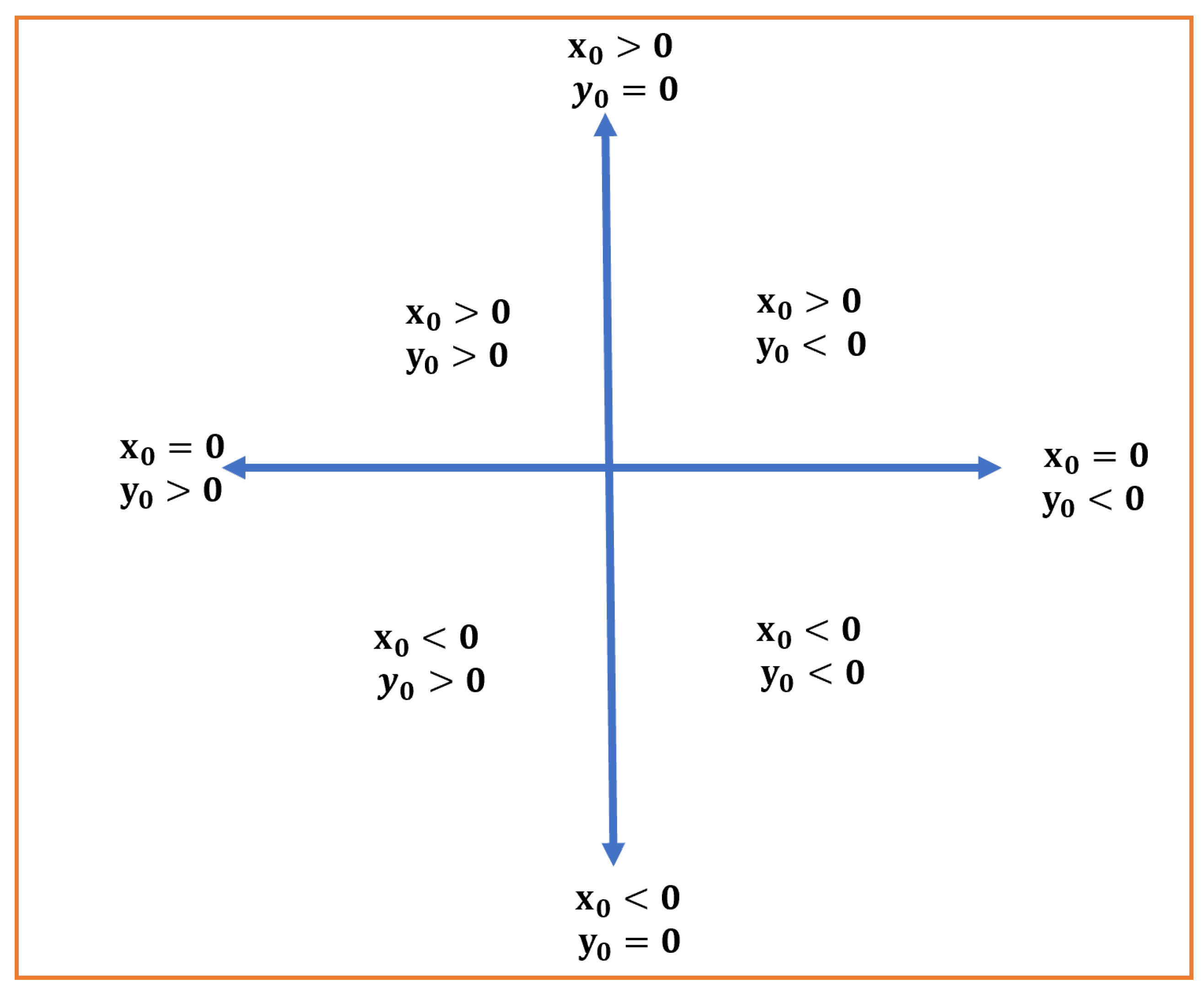
The direction of the opening of the crescent-shaped transverse intensity pattern depends on the sign and value of asymmetric parameters x 0 and y 0 (Equation (3)) which is graphically represented in Figure 2. As described in Figure 2, the crescent-like shape should have a left side opening when x 0 = 0 and y 0 > 0 which is shown in Figure 1a. When the magnitude of both asymmetric parameters is positive ( x 0 > 0 and y 0 > 0) then the crescent has a top-left side opening which can be seen from Figure 1b. Similarly, the x 0 and y 0 parameters that represent any other directional orientation of the crescent-shaped intensity profile, can be understood from Figure 2. Thus using the values ( x 0 , y 0 ) any desired asymmetricity and its directional orientation can be obtained.
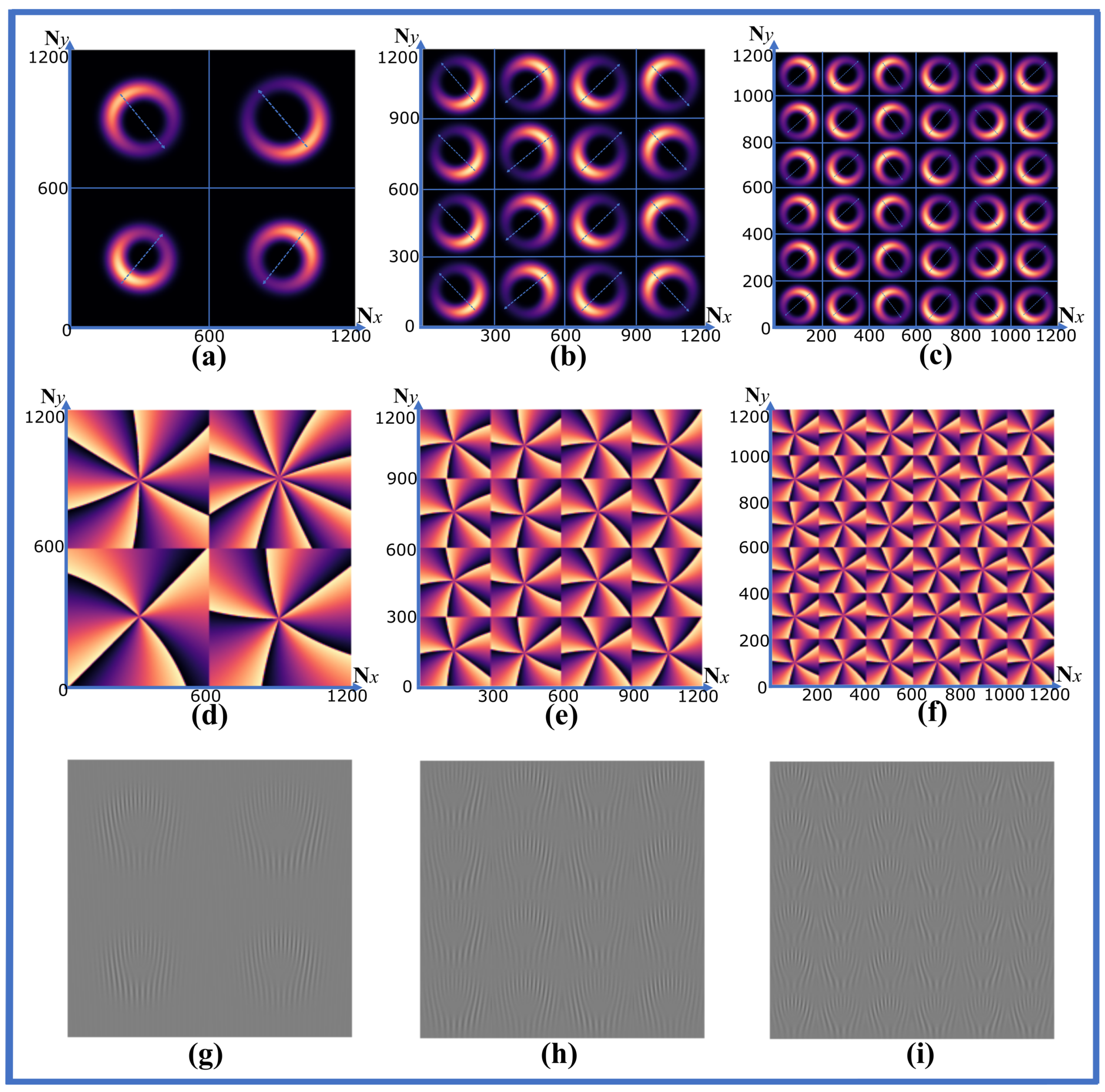
Now we will move our attention to beam array generation for which we employ the multiplexed hologram technique. Though the random/angularly multiplexed holograms (due to their larger size) offer higher numerical aperture (for a given hologram size) compared to spatially multiplexed ones, here we resort to the spatial multiplexing technique for the following reason. In the random/angular multiplexing technique, the complex amplitudes of all the individual beams in the array are spatially overlapped (added), each with a different random/carrier function. However, this overlap reduces the fringe contrast significantly since a ‘Gaussian envelope’ term (such as an amplitude mask) is dominant in an LG beam. Discarding the Gaussian envelope works to some extent in the case of a symmetric beam but significantly affects the characteristics of an asymmetric LG beam (especially the directional orientation). On the other hand, in a spatial multiplexing technique, the holograms that correspond to each beam in the array are spatially separated (tiled), thereby alleviating the issue. In order to realize this, first, a meshgrid of size L x × L y consisting of N x × N y pixels where L x and L y are the physical dimension (size) and N x and N y are the total numbers of pixels in the x and y-directions respectively. In order to generate a beam array of size n 1 × n 2 , the meshgrid is divided into n 1 × n 2 tiles such that each tile possesses an area of L x n 1 × L y n 2 and the total number of pixels associated with each tile is N x n 1 × N y n 2 . Here each tile corresponds to one asymmetric LG beam in the array. The simulated intensity and phase profile of an array consisting of different asymmetric LG beams are shown in the first and second row of Figure 3 respectively.
Figure 3a,d shows a 2 × 2 array in which the total area of the meshgrid is 1 × 1 cm 2 and the area of each tile (i.e, individual asymmetric beam) is 1 2 × 1 2 cm 2 . The total number of pixels associated with each individual beam in the array is 1200 2 × 1200 2 . Similarly, Figure 3b,e shows a 4 × 4 array, and Figure 3c,f shows a 6 × 6 array in which the area of the individual asymmetric beams are 1 4 × 1 4 cm 2 and 1 6 × 1 6 cm 2 respectively. The total number of pixels associated with the individual beam, in this case, is 1200 4 × 1200 4 for a 4 × 4 array and 1200 6 × 1200 6 for a 6 × 6 array. It is important to note that, while the array size (the number of beams in the array) is increased, the beam waist of each individual asymmetric beam decreases accordingly. In Figure 3a,d the beam waist of the single beam is 1.3 mm which reduces to 1 mm in the case of 4 × 4 array as shown in Figure 3b,e and 0.65 mm in case of 6 × 6 array as shown in 
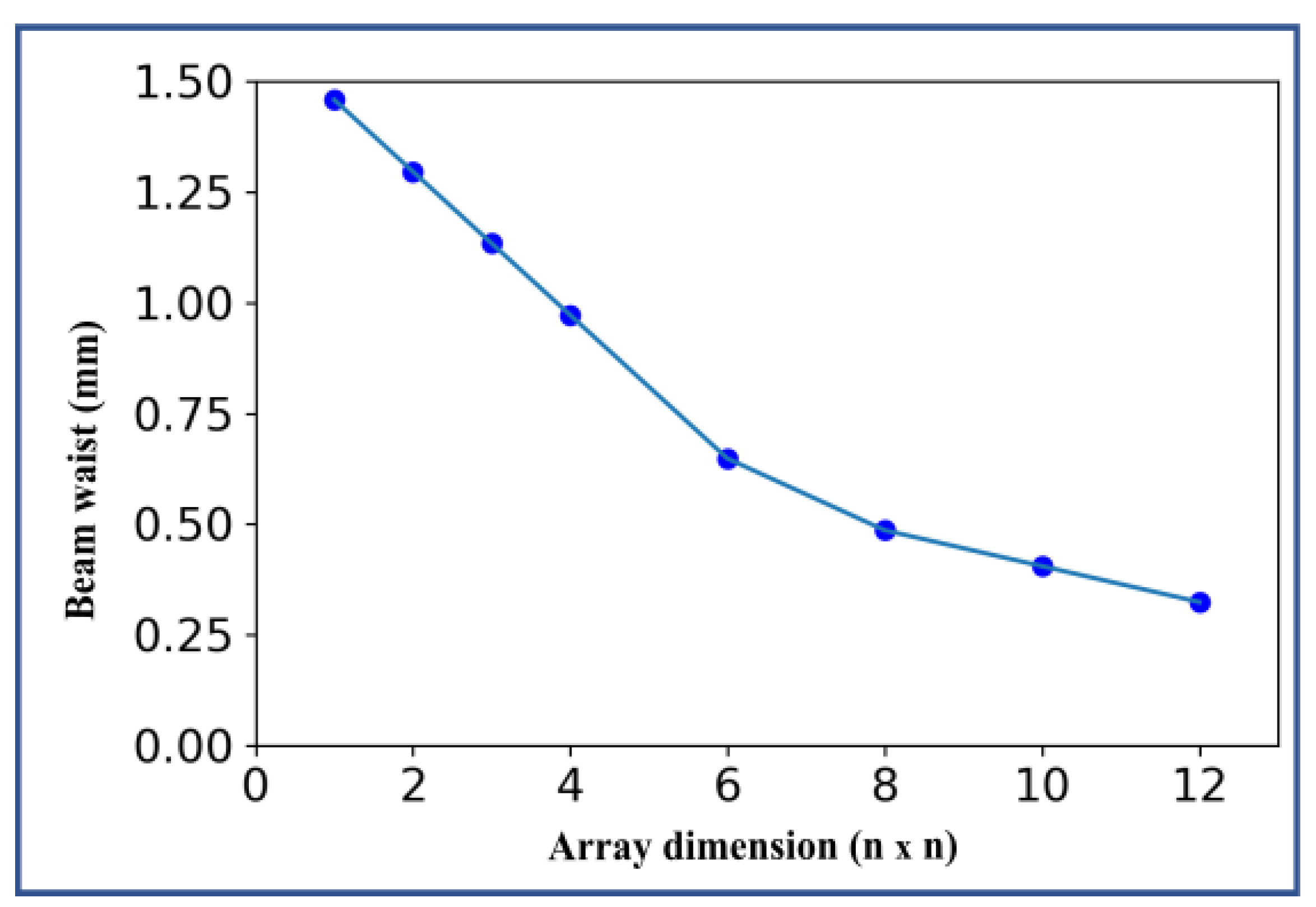
Figure 3c,f. The variation of the beam waist ( w 0 ) of the individual beam of the array with the size of the array (n × n) is shown in Figure 4.
Now we will discuss the actual CGH computation process. For simplicity, we concatenate all the tiles in the meshgrid and represent the resulting concatenated complex amplitude as E ( x , y ) (Equation (4))
E ( x , y ) = A ( x , y ) exp ( i ϕ ( x , y ) )
where A(x,y) and ϕ ( x , y ) corresponds to the amplitude and phase of the asymmetric array (consisting of multiple beams, spatially separated) which can be calculated using Equation (3). The CGH, which is also the transmittance function of the SLM ( T S L M ) is computed using the hologram encoding technique reported by Arrizon et al. [36] and is described in Equation (5),
T S L M = exp ( i ( J 1 1 ( C A ( x , y ) ) ) sin ( ϕ ( x , y ) + 2 π ( u 0 x + v 0 y ) ) )
where, J 1 1 is the inverse of the first order Bessel function, 2 π ( u 0 x + v 0 y ) represents a linear phase grating in which u 0 , v 0 are reciprocal of the linear grating period, A ( x , y ) [ 0 , 1 ] is the normalized amplitude, ϕ ( x , y ) [ 0 , 2 π ] is phase profile of the array and C m a x = 0.58 . The computed CGH pattern of 2 × 2 (Figure 3g), 4 × 4 (Figure 3h) and 6 × 6 (Figure 3h) asymmetric LG beam array for u 0 = 15 and v 0 = 0 is shown in the third row of Figure 3. These holograms also correspond to the amplitude and phase patterns shown in the above two rows of Figure 3, respectively. The experimental setup used for the practical generation of an asymmetric LG beam array is shown in Figure 5. The SLM used in the experiment was the LC-R 1080 reflective LCOS SLM from HOLOEYE Photonics AG (HOLOEYE Photonics AG, Berlin, Germany), which has a resolution of 1920 × 1200, a pixel pitch of 8.1 μ m, and a frame rate of 60 Hz. A half-wave plate (HWP) was used to adjust the polarization of the input beam being fed into the SLM. A 4f optical relay setup was used to separate the +1-order beam from the other diffracted and non-diffracted orders. The two lenses that were used in the 4f setup were of focal lengths of 50 cm and 10 cm, respectively. Finally, the intensity profile of the reconstructed beam array was captured using a CMOS camera (HAYEAR, model- HY6100 with pixel Size 2.0 × 2.0 μ m and Resolution of 3840 × 2160) kept at a distance of 120 cm (4f) from the SLM. It should be noted that the beam intensities must be captured as close as possible to the 4f plane. Away from the 4f plane, the beams start to overlap each other and also become distorted with distance.

3. Results

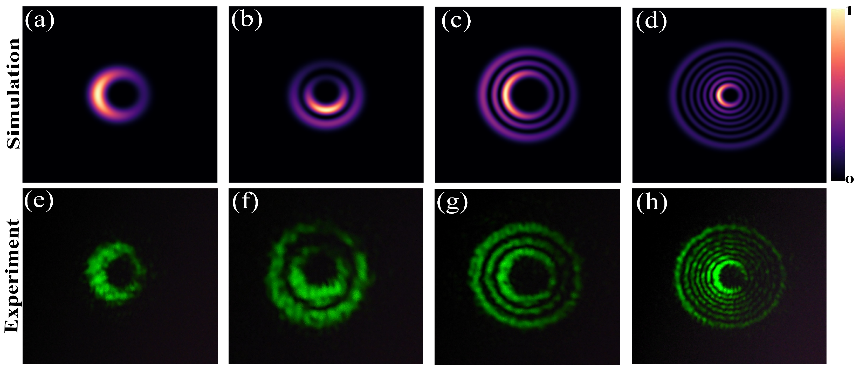
The captured intensity profile at the output plane for individual asymmetric LG beams (not array) for different set parameters is shown in Figure 6. The first and second rows show simulated and experimental results, respectively, for fixed beam waist ( w 0 = 1.5 mm ) and wavelength ( λ = 532 nm). The asymmetricity and mode indices are varied as follows, (a,e) x 0 = 0 , y 0 = 0.0001 i , p= 0, l= 5, (b,f) x 0 = 0.0001 i , y 0 = 0 , p= 1, l= 5, (c,g) x 0 = 0 , y 0 = 0.0001 i , p= 2, l= 10 and (d,h) x 0 = 0 , y 0 = 0.0001 i , p= 6, l= 5. The area of the meshgrid in this case is 1 × 1 cm 2 . We can see that the experimentally-captured intensity profile agrees well with that of the simulated ones.
Now, we will discuss the characteristics of a practically generated asymmetric LG beam array. Here, the directional orientation of the crescent-shaped intensity profile varies with the sign of asymmetricity values ( x 0 and y 0 ) as defined in Figure 2. Figure 7 shows the simulated and corresponding experimentally-observed intensity profiles for six different asymmetric LG beam arrays. Each array has a collection of individual beams with different asymmetricities and beam waists, as shown in Figure 7. In all the arrays, the radial index was kept fixed at p = 0, while the azimuthal index and asymmetric parameters x 0 and y 0 were allowed to vary. Figure 7a shows a 2 × 2 array where each beam in the array exhibits a different orientation, asymmetricity, and azimuthal mode. It can be observed that the individual beam size (intensity profile) increases with mode indices l = 5, 6, 7 and 8. On the other hand, all the individual beams in the array shown in Figure 7b,c have a fixed azimuthal index (l = 5) but have different directional orientation w.r.t asymmetricity. Figure 7d shows a 4 × 4 array, where the directional orientation of each beam varies from top to bottom and the beam modes vary from left to right with azimuthal index l = 6, 5, 4 and 3, respectively. No two beams in this array have the same directional orientation and mode index. From Figure 7b–d, we find that different information can be encoded in terms of directional orientation for a given mode index. In Figure 7e,f, we try to create patterned intensity profiles that can encode information in the ‘spatial distribution of modes’, similar to a QR code but at a higher density. Figure 7e shows a 12 × 12 array with the same azimuthal index l = 5, but a distribution of asymmetric orientations. The orientations are chosen such that the array spans a unique pattern in the transverse plane. Here, multiple beams possess the same directional orientation and mode index but are spatially distributed in a unique fashion in accordance with some information (to be encoded). The maximum array size that has been generated with radial and azimuthal indices p = 0 and l = 5, respectively, is 12 × 16 , which is shown in Figure 7f. Here, each beam has a beam waist of 0.2 mm and is enclosed in a tile of size 0.08 × 0.08 cm 2 with 100 × 100 effective number of pixels (in each tile). The 12 × 12 array shown in Figure 7e agrees well with the simulated intensity profile but the 12 × 16 array (Figure 7f), shows some crosstalk. Any further increase in array size or mode number will exceed the space-bandwidth limit of the SLM resulting in increased crosstalk. From the above results, we can conclude that an asymmetric beam array can be used to encode information in the mode number and directional orientation of each individual beam itself (Figure 7a–d), or be used to create a unique intensity pattern that encodes data in the unique spatial distribution of mode number and directional orientation (Figure 7e,f).
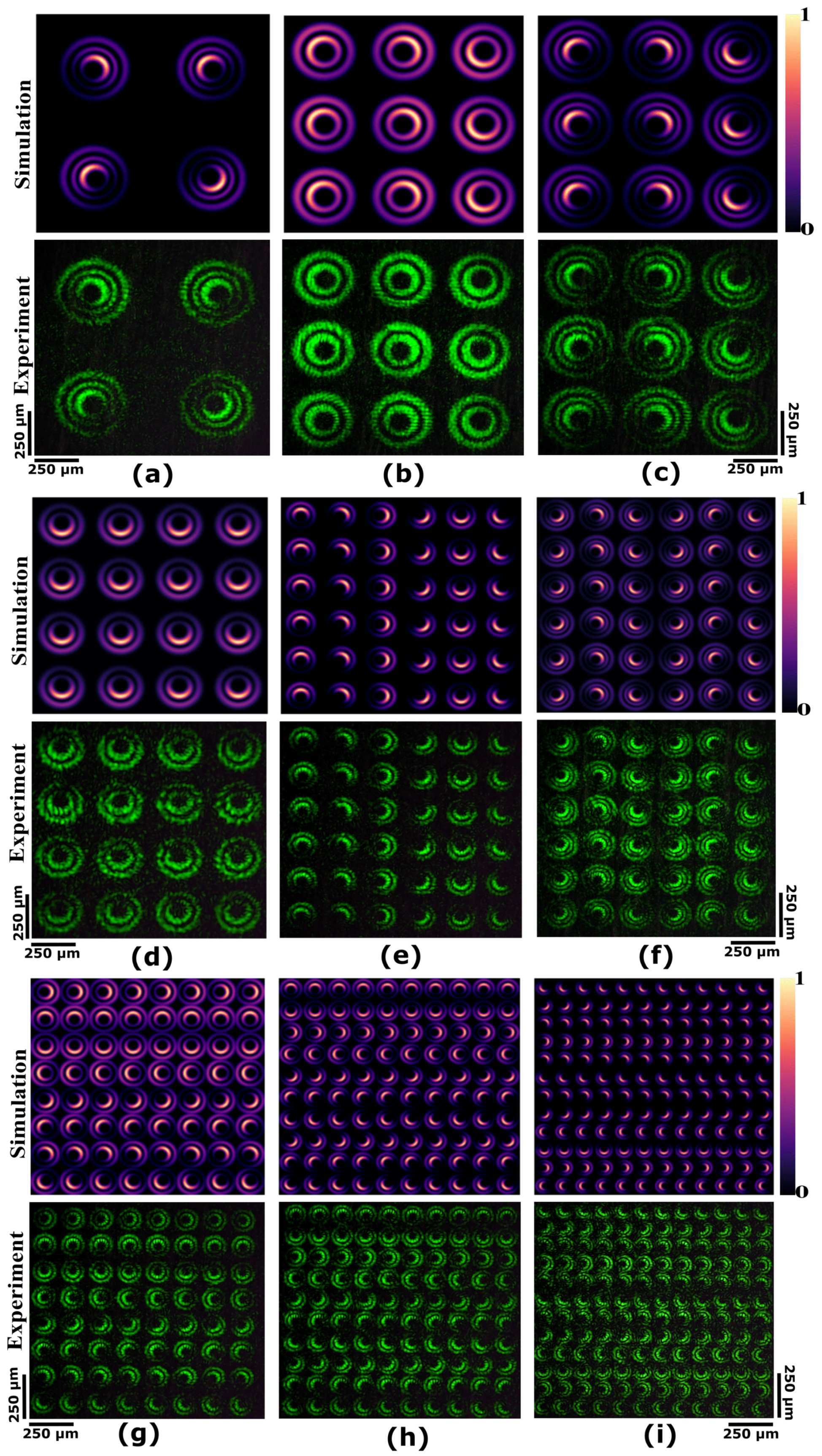
The encoded information can be further increased by setting a non-zero radial index to individual beams. The simulated and experimentally obtained intensity profile of asymmetric LG beam array with non-zero radial index (p) is shown in Figure 8. Figure 8a,c,f show asymmetric LG array of sizes of 2 × 2 , 3 × 3 , and 6 × 6 respectively for beam indices p = 2 and l = 5. Figure 8b,d,e,g–i shows an asymmetric LG array for varying array sizes up to 12 × 12 for beam indices p = 1 and l = 5. Here again, the direction of the opening in the crescent is determined according to the sign of asymmetric parameters x 0 and y 0 described in Figure 2. The experimentally obtained intensity profile of the array is well-matched with the simulated intensity profile, confirming the successful generation of an asymmetric LG beam array with non-zero radial(p) and azimuthal(l) indices. Here again, we can see that the information can be encoded either in mode number and directional orientation of individual beams or be used to create unique intensity patterns that encode data in the spatial distribution. We also would like to note that the increase in the azimuthal or radial index will result in the reduction of the total number of beams that can be accommodated in an array for a given hologram size. This is because the larger mode indices consume more spatial bandwidth of the hologram and also the beam diameter (transverse intensity distribution) increases with mode indices, occupying a larger area. The experiments reported here used a green laser (532 nm), but any other wavelength can be used as well, provided the desired wavelength is used in the hologram computation and the SLM is calibrated for that particular wavelength. If a DMD is used, then wavelength calibration will not be necessary [37].

4. Conclusions

The generation of an asymmetric LG beam array has been successfully implemented for the first time using computer-generated holography and a spatial multiplexing technique. An array as large as 12 × 16 has been successfully obtained for mode indices p = 0 and l = 5 with varying asymmetricity for each individual beam. It is shown that the asymmetric beams can exhibit different directional orientations for any given azimuthal or radial mode index. This will enable us to encode more information per mode index value and hence has better information capabilities compared to a symmetric beam. Moreover, the CGH can be tailored to create an arbitrary distribution of orientation in the beam array. This results in a unique intensity pattern across the transverse plane that can encode information in the spatial distribution itself. This method can also be extended to other asymmetric beams such as asymmetric Kummer beams, asymmetric optical Gaussian vortex beams, etc. The quality of the generated beam can be further improved by using the digital hologram printing technique [30], which offers a larger space-bandwidth product and a greater number of pixels for each individual beam. Quantifying each individual beam in an array is practically challenging. In the future, we intend to develop a simple technique that can quantify the OAM of each beam in an array. We believe this research will open new doors into realizing high-density data encoding in light signals and will assist developments in optical information processing and communication regimes.

Author Contributions

Conceptualization, B.J.J.; Methodology, S.K.S. and Y.A.; Validation, S.K.S.; Investigation, B.J.J. and K.K.; Software, Visualization, and formal analysis, S.K.S.; writing—original draft preparation, S.K.S.; writing—review and editing, B.J.J.; Supervision, B.J.J., K.K., N.T. and W.S. All authors have read and agreed to the published version of the manuscript.

Funding

This work is supported by the Strategic Promotion of Innovative Research and Development (JST S-Innovation), and is partly supported by JSPS KAKENHI Grant Number JP22H00535.

Institutional Review Board Statement

Not applicable.

Informed Consent Statement

Not applicable.

Data Availability Statement

Not applicable.

Acknowledgments

S.K.S. acknowledges the Ministry of Education, Sports and Culture of Japan (MEXT) scholarship provided by the Japanese Government for his studies at the Kyoto Institute of Technology.

Conflicts of Interest

The authors declare no conflict of interest and certify that they have no affiliations with or involvement in any organization or entity with any financial interest or non-financial interest in the subject matter or materials discussed in this manuscript.

Abbreviations

The following abbreviations are used in this manuscript:
LGLaguerre Gaussian
CGHComputer Generated Holography
SLMSpatial light modulator
CMOSComplementary metal oxide semiconductor

References

  1. Wang, J.; Liang, Y. Generation and Detection of Structured Light: A Review. Front. Phys. 2021, 9, 688284. [Google Scholar] [CrossRef]
  2. Forbes, A. Structured Light: Tailored for Purpose. Opt. Photon. News 2020, 31, 24–31. [Google Scholar] [CrossRef]
  3. Eyyuboğlu, H.T. Optical communication system using Gaussian vortex beams. J. Opt. Soc. Am. A 2020, 37, 1531–1538. [Google Scholar] [CrossRef] [PubMed]
  4. Li, S.; Pan, X.; Ren, Y.; Liu, H.; Yu, S.; Jing, J. Deterministic Generation of Orbital-Angular-Momentum Multiplexed Tripartite Entanglement. Phys. Rev. Lett. 2020, 124, 083605. [Google Scholar] [CrossRef] [PubMed]
  5. Yang, Y.; Ren, Y.; Chen, M.; Arita, Y.; Rosales-Guzmán, C. Optical trapping with structured light: A review. Adv. Photonics 2021, 3, 034001. [Google Scholar] [CrossRef]
  6. Angelsky, O.V.; Bekshaev, A.Y.; Hanson, S.G.; Zenkova, C.Y.; Mokhun, I.I.; Jun, Z. Structured light: Ideas and concepts. Front. Phys. 2020, 8, 114. [Google Scholar] [CrossRef]
  7. Chu, X.; Sun, Q.; Wang, J.; Lü, P.; Xie, W.; Xu, X. Generating a Bessel-Gaussian beam for the application in optical engineering. Sci. Rep. 2015, 5, 18665. [Google Scholar] [CrossRef] [PubMed] [Green Version]
  8. Hiekkamäki, M.; Prabhakar, S.; Fickler, R. Near-perfect measuring of full-field transverse-spatial modes of light. Opt. Express 2019, 27, 31456–31464. [Google Scholar] [CrossRef] [PubMed] [Green Version]
  9. Dimitrov, N.; Zhekova, M.; Paulus, G.G.; Dreischuh, A. Inverted field interferometer for measuring the topological charges of optical vortices carried by short pulses. Opt. Commun. 2020, 456, 124530. [Google Scholar] [CrossRef]
  10. Ren, Y.X.; Li, M.; Huang, K.; Wu, J.G.; Gao, H.F.; Wang, Z.Q.; Li, Y.M. Experimental generation of Laguerre–Gaussian beam using digital micromirror device. Appl. Opt. 2010, 49, 1838–1844. [Google Scholar] [CrossRef]
  11. Wang, M.; Ma, Y.; Sheng, Q.; He, X.; Liu, J.; Shi, W.; Yao, J.; Omatsu, T. Laguerre–Gaussian beam generation via enhanced intracavity spherical aberration. Opt. Express 2021, 29, 27783–27790. [Google Scholar] [CrossRef] [PubMed]
  12. Lu, J.; Cao, C.; Zhu, Z.; Gu, B. Flexible measurement of high-order optical orbital angular momentum with a variable cylindrical lens pair. Appl. Phys. Lett. 2020, 116, 201105. [Google Scholar] [CrossRef]
  13. Vijayakumar, A.; Bhattacharya, S. Design, fabrication, and evaluation of a multilevel spiral-phase Fresnel zone plate for optical trapping. Appl. Opt. 2012, 51, 6038–6044. [Google Scholar] [CrossRef]
  14. Zhang, B.; Zhao, D. Focusing properties of Fresnel zone plates with spiral phase. Opt. Express 2010, 18, 12818–12823. [Google Scholar] [CrossRef]
  15. Kotlyar, V.V.; Kovalev, A.A.; Soifer, V.A. Asymmetric Bessel modes. Opt. Lett. 2014, 39, 2395–2398. [Google Scholar] [CrossRef]
  16. Kotlyar, V.V.; Kovalev, A.A.; Skidanov, R.V.; Soifer, V.A. Asymmetric Bessel-Gauss beams. J. Opt. Soc. Am. A 2014, 31, 1977–1983. [Google Scholar] [CrossRef] [PubMed]
  17. Kotlyar, V.V.; Kovalev, A.A.; Abramochkin, E.G. Kummer laser beams with a transverse complex shift. J. Opt. 2019, 22, 015606. [Google Scholar] [CrossRef]
  18. Kotlyar, V.V.; Kovalev, A.A.; Porfirev, A.P. Asymmetric Gaussian optical vortex. Opt. Lett. 2017, 42, 139–142. [Google Scholar] [CrossRef]
  19. Zhu, J.; Zhu, K.; Ding, N.; Wang, T. Tricomi beams and nondiffracting sheet beams. Results Phys. 2021, 28, 104627. [Google Scholar] [CrossRef]
  20. Barcelo-Chong, A.; Estrada-Portillo, B.; Canales-Benavides, A.; Lopez-Aguayo, S. Asymmetric Mathieu beams. Chin. Opt. Lett. 2018, 16, 122601. [Google Scholar] [CrossRef]
  21. Kovalev, A.A.; Kotlyar, V.V. Family of three-dimensional asymmetric nonparaxial Lommel modes. In Proceedings of the Saratov Fall Meeting 2014: Optical Technologies in Biophysics and Medicine XVI; Laser Physics and Photonics XVI; and Computational Biophysics, Saratov, Russian, 23–26 September 2014; Genina, E.A., Derbov, V.L., Larin, K.V., Postnov, D.E., Tuchin, V.V., Eds.; International Society for Optics and Photonics, SPIE: Bellingham, WA, USA, 2015; Volume 9448, p. 944828. [Google Scholar] [CrossRef]
  22. Stsepuro, N.; Nosov, P.; Galkin, M.; Krasin, G.; Kovalev, M.; Kudryashov, S. Generating Bessel-Gaussian Beams with Controlled Axial Intensity Distribution. Appl. Sci. 2020, 10, 7911. [Google Scholar] [CrossRef]
  23. Kovalev, A.A.; Kotlyar, V.V.; Porfirev, A.P. Asymmetric Laguerre–Gaussian beams. Phys. Rev. A 2016, 93, 063858. [Google Scholar] [CrossRef]
  24. Gong, L.; Qiu, X.Z.; Ren, Y.X.; Zhu, H.Q.; Liu, W.W.; Zhou, J.H.; Zhong, M.C.; Chu, X.X.; Li, Y.M. Observation of the asymmetric Bessel beams with arbitrary orientation using a digital micromirror device. Opt. Express 2014, 22, 26763–26776. [Google Scholar] [CrossRef]
  25. Chen, Y.F.; Lai, Y.H.; Hsieh, M.X.; Hsieh, Y.H.; Tu, C.W.; Liang, H.C.; Huang, K.F. Wave representation for asymmetric elliptic vortex beams generated from the astigmatic mode converter. Opt. Lett. 2019, 44, 2028–2031. [Google Scholar] [CrossRef]
  26. Kovalev, A.A.; Kotlyar, V.V.; Porfirev, A.P. Optical trapping and moving of microparticles by using asymmetrical Laguerre–Gaussian beams. Opt. Lett. 2016, 41, 2426–2429. [Google Scholar] [CrossRef]
  27. Lin, Z.; Li, X.; Zhao, R.; Song, X.; Wang, Y.; Huang, L. High-efficiency Bessel beam array generation by Huygens metasurfaces. Nanophotonics 2019, 8, 1079–1085. [Google Scholar] [CrossRef] [Green Version]
  28. Lu, Y.; Jiang, B.; Lü, S.; Liu, Y.; Li, S.; Cao, Z.; Qi, X. Arrays of Gaussian vortex, Bessel and Airy beams by computer-generated hologram. Opt. Commun. 2016, 363, 85–90. [Google Scholar] [CrossRef]
  29. Suarez, R.A.; Neves, A.A.; Gesualdi, M.R. Generation and characterization of an array of Airy-vortex beams. Opt. Commun. 2020, 458, 124846. [Google Scholar] [CrossRef] [Green Version]
  30. Jackin, B.J.; Shirai, M.; Haginaka, H.; Kinashi, K.; Tsutsumi, N.; Sakai, W. Compact and Scalable Large Vortex Array Generation Using Azocarbazole Polymer and Digital Hologram Printing Technique. Nanoscale Res. Lett. 2022, 17, 1–13. [Google Scholar] [CrossRef]
  31. Rosales-Guzmán, C.; Bhebhe, N.; Mahonisi, N.; Forbes, A. Multiplexing 200 spatial modes with a single hologram. J. Opt. 2017, 19, 113501. [Google Scholar] [CrossRef]
  32. Wang, D.; Li, Y.; Hu, X.; Jin, L. Tailoring Ince-Gaussian arrays based on a computer-generated hologram. Appl. Opt. 2021, 60, 7172–7176. [Google Scholar] [CrossRef] [PubMed]
  33. Wang, D.; Jin, L.; Rosales-Guzmán, C.; Gao, W. Generating arbitrary arrays of circular Airy Gaussian vortex beams with a single digital hologram. Appl. Phys. B 2021, 127, 22. [Google Scholar] [CrossRef]
  34. Singh, S.K.; Haginaka, H.; Jackin, B.J.; Kinashi, K.; Tsutsumi, N.; Sakai, W. Generation of Ince-Gaussian Beams Using Azocarbazole Polymer CGH. J. Imaging 2022, 8, 144. [Google Scholar] [CrossRef] [PubMed]
  35. Goorden, S.A.; Bertolotti, J.; Mosk, A.P. Superpixel-based spatial amplitude and phase modulation using a digital micromirror device. Opt. Express 2014, 22, 17999–18009. [Google Scholar] [CrossRef] [Green Version]
  36. Arrizón, V.; Ruiz, U.; Carrada, R.; González, L.A. Pixelated phase computer holograms for the accurate encoding of scalar complex fields. J. Opt. Soc. Am. A 2007, 24, 3500–3507. [Google Scholar] [CrossRef] [PubMed]
  37. Wang, X.; Zhang, H. Diffraction Characteristics of a Digital Micromirror Device for Computer Holography Based on an Accurate Three-Dimensional Phase Model. Photonics 2023, 10, 130. [Google Scholar] [CrossRef]
Figure 1. Simulated intensity (First row) and phase profile (second row) of asymmetric LG beams for different values of x 0 , y 0 , p, and l. (a,e) x 0 = 0 , y 0 = 0.0002 i , p = 1 and l = 5 (b,f) x 0 = 0.0003 i , y 0 = 0.0002 i , p = 2 and l = 5 (c,g) x 0 = 0.0003 i , y 0 = 0 , p = 3 and l = 5 (d,h) x 0 = 0.001 i , y 0 = 0.001 i , p = 3 and l = 5 for λ = 532 nm , w 0 = 1.2 mm and z = 0 .
Photonics 10 00247 g001
Figure 2. Variation of sign and value of asymmetric parameters that determines the direction of opening of crescent-shaped intensity pattern exhibited by asymmetric LG beams.
Photonics 10 00247 g002
Figure 3. Simulated intensity (First row), phase profile (second row) and CGH (third row) of asymmetric LG beams array of size (a,d,g) 2 × 2 , (b,e,h) 4 × 4 and (c,f,i) 6 × 6 for different values of x 0 , y 0 , p, and l.
Photonics 10 00247 g003
Figure 4. Variation of beam waist of the individual beam of an array with the size of the array (n × n).
Photonics 10 00247 g004
Figure 5. Schematic of the optical setup used for practical generation of asymmetric LG beam array. (BE: Beam expander; SF: Spatial filter; HWP: Half wave plate; SLM: Spatial light modulator).
Photonics 10 00247 g005
Figure 6. Simulated (first row) and experimental (second row) intensity profiles of asymmetric LG beam for w 0 = 1.5 mm, λ = 532 nm, (a,e) x 0 = 0 , y 0 = 0.0001 i , p = 0, l= 5, (b,f) x 0 = 0.0001 i , y 0 = 0 , p = 1, l = 5, (c,g) x 0 = 0 , y 0 = 0.0001 i , p = 2, l = 10 and (d,h) x 0 = 0 , y 0 = 0.0001 i , p = 6, l = 5.
Photonics 10 00247 g006
Figure 7. Simulation and experimental intensity profile of asymmetric LG beam array with different asymmetricity and array dimensions (a) 2 × 2 with radial index = 0 and azimuthal index = 3, 4, 5 and 6, (b) 2 × 2 with radial index = 0 and azimuthal index = 5, (c) 2 × 2 with radial index = 0 and azimuthal index = 5, (d) 4 × 4 with radial index = 0 and azimuthal index = 3, 4, 5 and 6, (e) 12 × 12 with radial index = 0 and azimuthal index = 5, and (f) 12 × 16 with radial index = 0 and azimuthal index = 5.
Photonics 10 00247 g007
Figure 8. Simulated and experimental intensity profile of asymmetric LG beam array of different asymmetricity and array dimensions, (a,c,f) radial index = 2 and azimuthal index = 5, (b,d,e,g,h,i) radial index = 1 and azimuthal index = 5.
Photonics 10 00247 g008
Disclaimer/Publisher’s Note: The statements, opinions and data contained in all publications are solely those of the individual author(s) and contributor(s) and not of MDPI and/or the editor(s). MDPI and/or the editor(s) disclaim responsibility for any injury to people or property resulting from any ideas, methods, instructions or products referred to in the content.

