Communication

Transmission Matrix-Inspired Optimization for Mode Control in a 6 × 1 Photonic Lantern-Based Fiber Laser

1
College of Advanced Interdisciplinary Studies, National University of Defense Technology, Changsha 410073, China
2
Nanhu Laser Laboratory, National University of Defense Technology, Changsha 410073, China
3
State Key Laboratory of Pulsed Power Laser Technology, Changsha 410073, China
*
Authors to whom correspondence should be addressed.
These authors contributed equally to this work.
Photonics 2023, 10(4), 390; https://doi.org/10.3390/photonics10040390
Submission received: 14 February 2023 / Revised: 15 March 2023 / Accepted: 21 March 2023 / Published: 1 April 2023
(This article belongs to the Section Lasers, Light Sources and Sensors)

Abstract

:
A photonic lantern is a coherent beam combination device that can increase the fiber laser brightness by adaptively controlling the input light properties, such as phase, intensity, and polarization. However, the control effect is closely related to the initial optical field, which affects the convergence speed to obtain the optimum solutions. In this work, we propose a novel control strategy using the prior structural information of the photonic lantern. Taking a 6 × 1 photonic lantern as an example, we calculate the transmission matrix of the photonic lantern. The initial optical field conditions, fed as the control inputs, for various mode outputs can be obtained. Compared with the random and equal amplitude control methods, the preset method from the transmission matrix presents a significant improvement of the desired mode content. Our optimization method is generally useful for adaptive control systems to improve their performance, taking advantage of their own structural information.

1. Introduction

The “photonic lantern” (PL) is an optical waveguide, which enables low-loss light transmission and mode coupling between single-mode fibers (SMFs) and multiple mode fibers (MMFs) [1,2,3,4]. In 2005, Leon-Saval et al. demonstrated such devices when fabricating a multi-mode filter, the performance of which matched the SMF performance [5]. When used for optical signal processing in large telescopes, PL-based filters can filter out the bright and narrow hydroxyl emissions between 1000 nm and 1800 nm to improve the visibility of desired signals [6]. In optical communication, a PL can be used as a spatial multiplexer with mode-selective ability and low insertion loss [7,8,9,10,11]. Compared with a traditional spatial multiplexer [12,13,14,15,16,17], PLs are all-fiber devices that can greatly reduce the loss caused by the space optical path. However, it must be pointed out that the multiple abilities of PLs are limited by the number of their input channels. In addition to application in the low-power regime, researchers explored PL to be used in fiber lasers. With the adaptive spatial mode control in 3 × 1 PL, the power output after scaling has reached 1.27 kW for the fundamental mode using a large-mode-area (LMA) fiber [18,19], revealing great potential for achieving high-power laser output with high beam quality.
LMA fiber is used to increase the threshold of nonlinear effects in the power growth of the laser by increasing the modal field area [20,21]. However, in high power systems, the refractive index of the fiber changes with the temperature, which enables the mode coupling to be instable at kilohertz or even faster [22,23]. This phenomenon is called transverse mode instability (TMI) [24] and it can lead to the degradation of the beam quality. The conventional method of fiber coiling can filter high-order mode (HOM) signals, but it will also lead to power loss. It is difficult to solve these problems with the laser itself [25,26]. Therefore, active control methods have been used to suppress the instability of the transverse modes. Usually, the stability control of the two lowest linearly polarized (LP) modes, LP01 and LP11 mode, can be reached when the optical intensity is used as the evaluation function [27,28,29,30]. For example, an approach had been attempted to mitigate TMI by a dynamic excitation of the fiber modes using an acousto-optic deflector [31]. However, they only considered the optical amplitude, neglecting the important phase information. Such a control scheme is difficult to achieve the stable output of HOMs.
To solve this challenge, we combine the PL technology with a LMA fiber. Using the linear correlation between the input and output of the PL, we can modulate the input conditions at the side of its SMFs in real time to realize the output of a specific mode in the LMA fiber. The applicability of this scheme has been demonstrated in the MIT experiments [18,19]. They firstly described the correspondence between the input and output of PL with the help of transmission matrix (TM). However, the 3 × 1 PL can only achieve stable control of three modes. Achieving HOM control requires higher-order PLs [7].
In this paper, we propose a mode control scheme based on a 6 × 1 PL. We use the stochastic parallel gradient descent (SPGD) algorithm to control the phase and amplitude at the input of the PL in real time, and preset the initial amplitude condition according to the inverse solution of the TM of PL. To enhance the control of HOMs, we also take the content of the relevant modes as an evaluation function instead of using the received power of the photodetector, which is commonly used in experiments. In this work, we first simulate two amplitude control methods, namely random amplitude control and equal amplitude control. We also compare their effects on controlling the fundamental mode and HOMs with the control scheme proposed in this paper, namely, transmission matrix-inspired control.

2. Materials and Methods

2.1. The Transmission Matrix of the Photonic Lantern

The PL is made by splicing a tapered SMF bundle with a MMF. The transverse size of the SMF bundle is continuously decreased, and the mode evolution occurs when the beam is transmitted in it. Since this size decrease is slow enough [32], there is a linear relationship between the input and output light fields of the PL. In general, the PL is considered as a linear optical device, which can be characterized mathematically as a matrix that maps the input vector to the output vector [18]:
A V = U
where V is a column vector containing the amplitude and phase inputs of the SMFs, and U is a column vector representing the complex amplitude coefficients of the supported modes. A is the TM of the PL. TM is a complex quantity used to describe the transmission characteristics of optical waveguides [33]. Much research revolves around the measurement, calculation and application of the TMs of special optical waveguides [34,35,36,37]. In this paper, we numerically calculate the TMs of PLs by simulating the mode evolution process in PLs based on the beam propagation method (BPM) [38,39,40]. Each input fiber of PL is injected into the fundamental mode and the optical field distribution obtained in the output fiber is calculated by BPM. Using the mode decomposition algorithm, we can obtain the complex amplitude coefficients of each supported LP mode. Finally, the ideal TM of PL is inversely calculated according to Formula (1). The numerical calculation results of the TM of the 6 × 1 PL are as follows:
0.61 0.35 0.35 0.35 0.35 0.35 0 0.63 e i ( 0.83 π ) 0.19 e i ( 0.83 π ) 0.51 e i ( 0.17 π ) 0.51 e i ( 0.17 π ) 0.19 e i ( 0.83 π ) 0 0 0.60 e i ( 0.83 π ) 0.37 e i ( 0.83 π ) 0.37 e i ( 0.17 π ) 0.60 e i ( 0.17 π ) 0 0.63 e i ( 0.94 π ) 0.51 e i ( 0.06 π ) 0.19 e i ( 0.94 π ) 0.19 e i ( 0.94 π ) 0.51 e i ( 0.06 π ) 0 0 0.37 e i ( 0.94 π ) 0.60 e i ( 0.06 π ) 0.60 e i ( 0.94 π ) 0.37 e i ( 0.06 π ) 0.73 e i ( 0.93 π ) 0.27 e i ( 0.07 π ) 0.27 e i ( 0.07 π ) 0.27 e i ( 0.07 π ) 0.27 e i ( 0.07 π ) 0.27 e i ( 0.07 π )
Experimentally, the TM of an actual PL can be measured using the method in reference [33]. Due to the limitation of manufacturing technology, the TM obtained by theoretical calculation will be slightly different from the TM measured by the experiment. Once the TM of the PL is calculated or measured, if a specific output light field is needed, the input condition can be calculated according to:
V = A 1 U
In the actual optical system, it is very easy to set the input amplitudes as the calculated results of Equation (3). However, due to environmental disturbance, optical path difference and other factors, the phase of each input path is constantly changing. Therefore, in order to realize the mode control by PL, it is necessary to control each input phase by means of adaptive optics.

2.2. Stochastic Parallel Gradient Descent Algorithm

In adaptive optics, according to the signal detected by the output end, the controller actively modulates the information of the input end. The control algorithm is key to achieve good control effects. In our system, stochastic parallel gradient descent (SPGD) is chosen to be the control algorithm. SPGD algorithm is simple and effective, so that it is widely adopted in the field of optics to achieve a phase-locked loop [41,42,43,44,45]. In the PL-based mode control system, we also use SPGD to control the phase of each input. In particular, we compared the mode control effect under three prefabricated amplitude conditions. Figure 1 shows the basic control loop of SPGD. Evaluation function J, random disturbance voltage δu and gain coefficient γ are the three main parameters in the SPGD algorithm. In the control of the SPGD algorithm, the system generates a set of voltages with opposite perturbations below a certain threshold, denoted as δu+ and δu, respectively. The effect of the disturbances in both directions on the performance can be expressed as J+ and J. We can update the input u following this formula in Equation (4). The iteration continues and the evaluation function J converges to a better solution. It can be seen that disturbance voltage δu and gain coefficient γ determine the stability and convergence speed of the control.
u n + 1 = u n + γ × J + J J + + J × δ u n
In our simulations, the evaluation function J is the mode content of the target mode. We make a mode decomposition of the output optical field in real time to the complex amplitude coefficients of every mode. Additionally, J is the real of the desired mode’s complex amplitude coefficients. Voltage u is applied to each phase modulator at each input channel. The final parameters are set as follows: the perturbation voltage for the phase control is 0.07 V and the gain coefficient is 200; the perturbation voltage for the amplitude control is 0.04 V and the gain coefficient is 150. In the actual optical system, the frequency of phase disturbance is below kHz, and the control bandwidth of SPGD can be up to 10 kHz, so the system can realize real-time mode control.
The focus of the following research is the control condition. We studied the stability and convergence speed of the SPGD algorithm in controlling the input phase under three different prefabricated input amplitude conditions of the PL.

3. Results and Discussion

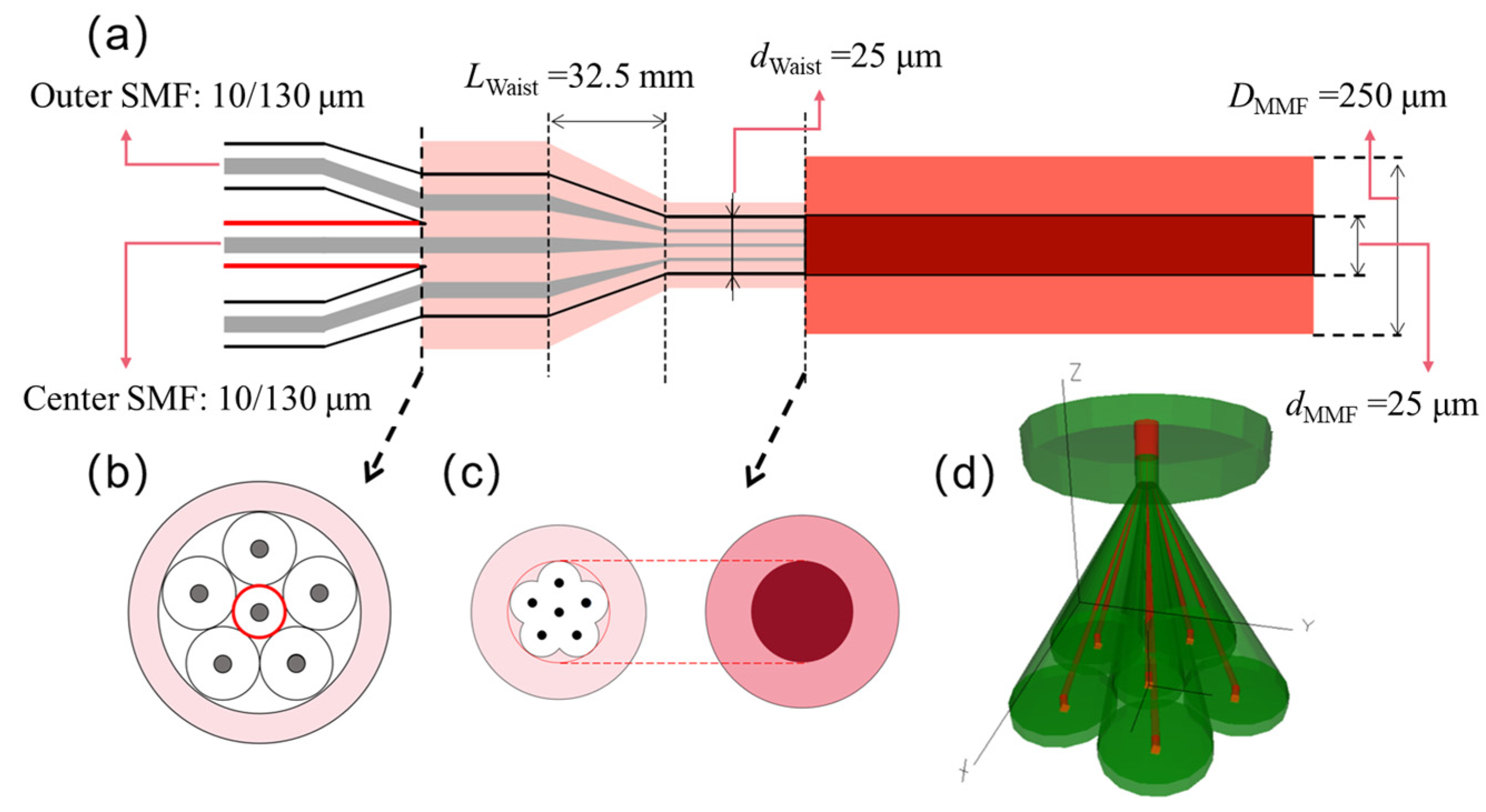
3.1. The 6 × 1 Photonic Lantern

The 6 × 1 PL used in our system satisfies the structure requirements: mode matching, adiabatic cone tapering and reasonable arrangement [1]. Following these rules, the propagation loss of multiple modes can be minimal in forward and backward directions.
The “mode matching” means that the number of supported modes in the MMF needs to match the number of SMFs in the input channel. Six 10/130 (NA = 0.08) SMFs are selected as the single-mode input, and a 25/250 (NA = 0.065) MMF is used as the multimode output, as shown in Figure 2. The approximate value of the number of modes supported in a multimode fiber Nm can be derived from the following expressions:
N m π d N A 2 λ 2
where d is the diameter of the fiber core, λ is the laser wavelength of 1064 nm, and NA is the numerical aperture of the output fiber. Nm is calculated to be 6.024, which means the MMF supports 6 LP modes. Therefore, 6 × 1 PL in this paper satisfies the mode matching condition. To meet the reasonable arrangement of the 6 × 1 PL, the outer five fibers are arranged following a pentagon and the other fiber is in the geometric center. However, if all six fibers are of the same size, there will be more gaps between the outer fibers. To fill the gap, we can experimentally erode the cladding of the center fiber from 130 μm to 91 μm. After this treatment, the SMFs fit closely to each other and are not easily slipped during the tapering process. We accordingly change the diameter of the fiber cladding in the simulation. The last requirement is the “adiabatic taper tapering”. In the taper pulling process, the taper angle Ω < 0.01 rad in the taper region [19]. This means that for every 10 μm decrease in the fiber bundle, the taper length increases by at least 1 mm. After the taper pulling, the diameter of the 6 × 1 PL decreases from 280 μm to 25 μm. The minimum length of the tapered region can be calculated to be 32.5 mm. The PL is then integrated into a fiber laser system, the details of which can be found in ref. [18].

3.2. Random Amplitude

To set the initial values of the SMF amplitudes, one common strategy is to use the random number first before SPGD algorithm comes into play. We thus simulate 6 × 1 PL using first six modes (LP01, LP11e, LP11o, LP21e, LP21o and LP02). Following the initial amplitude setting, SPGD algorithm updates the values according to the evaluation function. Initially, there is a transition period when multiple modes couple to each other. Then, the desired mode content starts to rise rapidly and stabilize. However, the mode content cannot rise to unity as other modes co-exist. This cannot improve much as the system has fallen into a local optimal solution, so extending the time window does not help. As a result, the mode content for these modes are 78.9% (LP01), 30.4% (LP11e), 44.4% (LP11o), 67.7% (LP21e), 42.7% (LP21o) and 22.9% (LP02), respectively. The highest mode content is only near 80%. As LP01 and LP02 are so close in amplitude distribution, SPGD algorithm cannot separate them well. For example, in Figure 3f, we find that controlling LP02 is rather difficult, reaching around 20% compared to 55% of LP01 mode.

3.3. Preset the Equal Amplitude

Another usually adopted strategy to initialize the amplitude input is to have the equal amplitude. From the control effect shown in Figure 4, the final beam shape is more symmetrical than the previous ones. Additionally, the time period to stabilize is shorter. The final mode content is also higher. Especially in controlling LP01 mode, the percentage is as high as 99.1%. However, in controlling LP11e (70.0%), LP11o (78.7%), LP21e (65.0%) and LP21o (59.5%) modes, the stabilized percentage is still not significantly improved. In controlling LP02 mode, the LP01 mode still has the largest percentage (30% for LP02 and 69.3% for LP01).

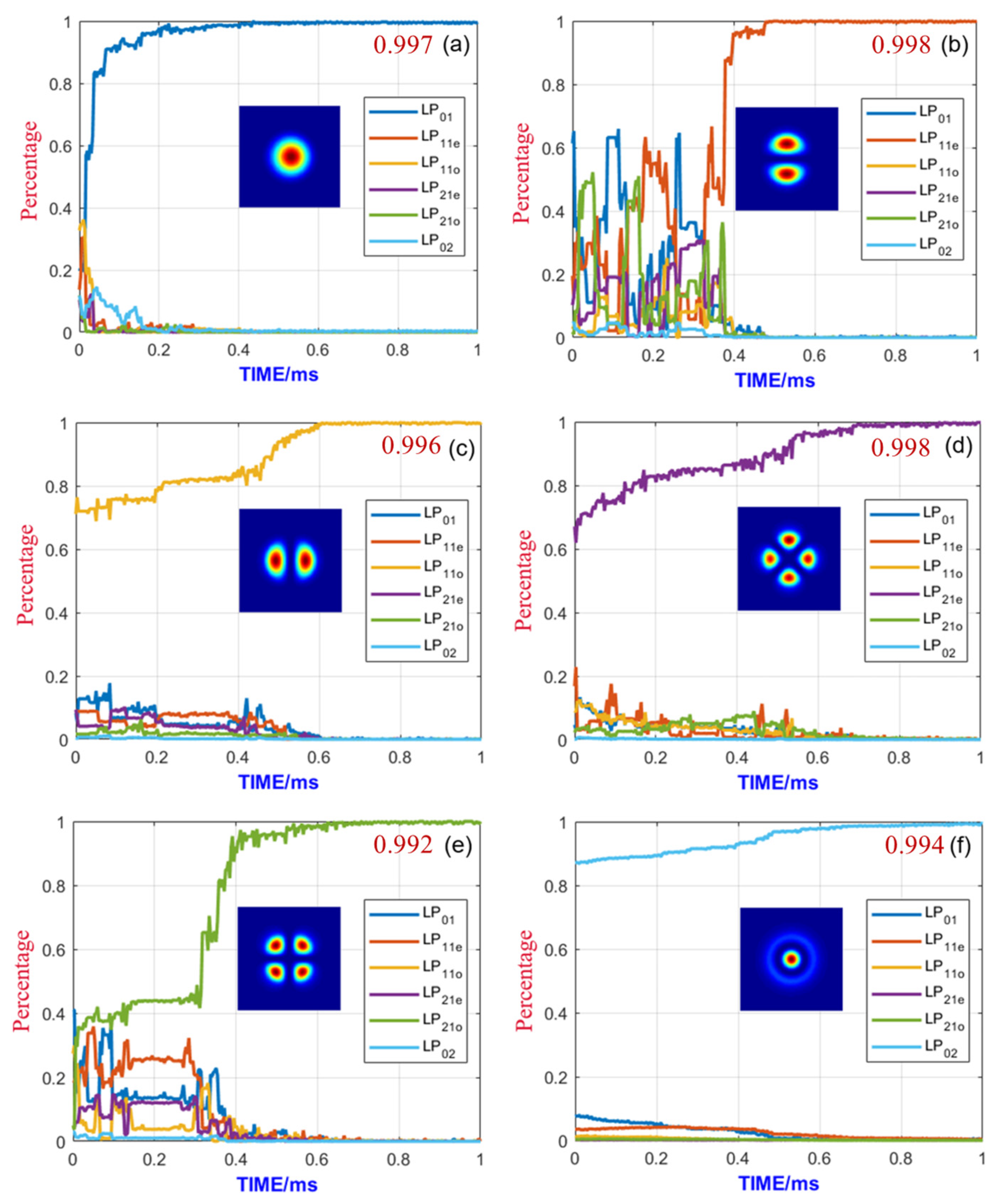
3.4. Preset Amplitude Based on Transmission Matrix

We propose a novel method to initialize the amplitude inputs using the TM of the PL. If the PL is well-fabricated, the optimal solution should be quite close to the values calculated from TM. The simulation results are shown in Figure 5. For all six modes, we find that the final mode content is more than 99% within 1 ms. The beam shape is almost identical to the control target. For LP02 mode, the control effect is much better than the other methods.
We summarize our simulation results in Table 1. Although the equal amplitude control has advantages in LP01 control, both schemes of random amplitude control and equal amplitude control have defects in mode control. The reason is that the optimization pathway of the 6 × 1 PL has many local optimal solutions, and the SPGD algorithm may fall into these local optimal solutions. Using the TM of the PL itself, we are able to achieve a much better control result compared with two other methods of setting amplitude, either random or equal.

4. Conclusions

We compare three methods to set the initial amplitude in SPGD algorithm for optimizing mode control in a 6 × 1 PL based fiber laser. The methods using random and equal amplitudes can achieve moderate beam contents, but cannot control LP02 mode, as a result of falling into local optimum solutions. Inspired from the physical character of the PL, we can calculate the out amplitude input requirement for controlling certain modes. Using these PL-related initial amplitudes, the fiber laser system can achieve almost perfect mode content for all six modes within 1 ms. Our work demonstrates that knowing the physical properties of the optical system (such as TM of the PL) can significantly improve the optimization results, and should be applicable to other optimization problems in optical and photonic fields.

Author Contributions

Conceptualization, W.L.; methodology, W.L.; software, Y.L.; validation, C.L., Y.L. and J.C.; formal analysis, C.L. and Y.L.; investigation, C.L. and Y.L.; resources, W.L. and D.Z.; data curation, C.L.; writing—original draft preparation, C.L.; writing—review and editing, Y.L. and J.Z.; visualization, C.L. and J.Z.; supervision, W.L., P.L., J.Z. and Q.Z.; project administration, W.L. and Z.J.; funding acquisition, W.L. All authors have read and agreed to the published version of the manuscript.

Funding

This research was funded by National Natural Science Foundation of China, grant number 12074432.

Institutional Review Board Statement

Not applicable.

Informed Consent Statement

Not applicable.

Acknowledgments

We are grateful for the lab support offered by Qi Xiang and Na Zhao.

Conflicts of Interest

The authors declare no conflict of interest.

References

  1. Leon-Saval, S.G.; Argyros, A.; Bland-Hawthorn, J. Photonic lanterns: A study of light propagation in multimode to single-mode converters. Opt. Express 2010, 18, 8430–8439. [Google Scholar] [CrossRef] [PubMed] [Green Version]
  2. Leon-Saval, S.G.; Argyros, A.; Bland-Hawthorn, J. Photonic lanterns. Nanophotonics 2013, 2, 429–440. [Google Scholar] [CrossRef] [Green Version]
  3. Birks, T.A.; Gris-Sanchez, I.; Yerolatsitis, S.; Leon-Saval, S.G.; Thomson, R.R. The photonic lantern. Adv. Opt. Photonics 2015, 7, 107–167. [Google Scholar] [CrossRef] [Green Version]
  4. Noordegraaf, D.; Skovgaard, P.M.W.; Maack, M.D.; Bland-Hawthorn, J.; Haynes, R.; Laegsgaard, J. Multi-mode to single-mode conversion in a 61 port Photonic Lantern. Opt. Express 2010, 18, 4673–4678. [Google Scholar] [CrossRef] [PubMed] [Green Version]
  5. Leon-Saval, S.G.; Birks, T.A.; Bland-Hawthorn, J.; Englund, M. Multimode fiber devices with single-mode performance. Opt. Lett. 2005, 30, 2545–2547. [Google Scholar] [CrossRef] [PubMed]
  6. Bland-Hawthorn, J.; Ellis, S.C.; Leon-Saval, S.G.; Haynes, R.; Roth, M.M.; Lohmannsroben, H.G.; Horton, A.J.; Cuby, J.G.; Birks, T.A.; Lawrence, J.S.; et al. A complex multi-notch astronomical filter to suppress the bright infrared sky. Nat. Commun. 2011, 2, 581. [Google Scholar] [CrossRef] [Green Version]
  7. Leon-Saval, S.G.; Fontaine, N.K.; Salazar-Gil, J.R.; Ercan, B.; Ryf, R.; Bland-Hawthorn, J. Mode-selective photonic lanterns for spacedivision multiplexing. Opt. Express 2014, 22, 1036–1044. [Google Scholar] [CrossRef]
  8. Fontaine, N.K.; Leon-Saval, S.G.; Ryf, R.; Gil, J.R.S.; Ercan, B.; Bland-Hawthorn, J. Mode-selective dissimilar fiber photonic-lantern spatial multiplexers for few-mode fiber. In Proceedings of the 39th European Conference and Exhibition on Optical Communication (ECOC 2013), London, UK, 22–26 September 2013; pp. 1–3. [Google Scholar]
  9. Huang, B.; Fontaine, N.K.; Ryf, R.; Guan, B.; Leon-Saval, S.G.; Shubochkin, R.; Sun, Y.; Lingle, R.; Li, G.F. All-fiber mode-group-selective photonic lantern using graded-index multimode fibers. Opt. Express 2015, 23, 224–234. [Google Scholar] [CrossRef] [Green Version]
  10. Ryf, R.; Fontaine, N.K.; Montoliu, M.; Randel, S.; Ercan, B.; Chen, H.; Chandrasekhar, S.; Gnauck, A.H.; Leon-Saval, S.G.; Bland-Hawthorn, J.; et al. Photonic-Lantern-Based Mode Multiplexers for Few-Mode-Fiber Transmission. In Proceedings of the Optical Fiber Communications Conference and Exhibition (OFC), San Francisco, CA, USA, 9–13 March 2014. [Google Scholar]
  11. Lopez-Galmiche, G.; Eznaveh, Z.S.; Antonio-Lopez, J.E.; Benitez, A.M.V.; Asomoza, J.R.; Mondragon, J.J.S.; Gonnet, C.; Sillard, P.; Li, G.; Schulzgen, A.; et al. Few-mode erbium-doped fiber amplifier with photonic lantern for pump spatial mode control. Opt. Lett. 2016, 41, 2588–2591. [Google Scholar] [CrossRef]
  12. Arrizón, V.; Ruiz, U.; Carrada, R.; González, L.A. Pixelated phase computer holograms for the accurate encoding of scalar complex fields. J. Opt. Soc. Am. A 2007, 24, 3500–3507. [Google Scholar] [CrossRef]
  13. Goorden, S.A.; Bertolotti, J.; Mosk, A.P. Superpixel-based spatial amplitude and phase modulation using a digital micromirror device. Opt. Express 2014, 22, 17999–18009. [Google Scholar] [CrossRef] [PubMed] [Green Version]
  14. Forbes, A.; Dudley, A.; McLaren, M. Creation and detection of optical modes with spatial light modulators. Adv. Opt. Photonics 2016, 8, 200–227. [Google Scholar] [CrossRef]
  15. Rothe, S.; Daferner, P.; Heide, S.; Krause, D.; Schmieder, F.; Koukourakis, N.; Czarske, J.W. Benchmarking analysis of computer generated holograms for complex wavefront shaping using pixelated phase modulators. Opt. Express 2021, 29, 37602–37616. [Google Scholar] [CrossRef] [PubMed]
  16. Labroille, G.; Denolle, B.; Jian, P.; Genevaux, P.; Treps, N.; Morizur, J.-F. Efficient and mode selective spatial mode multiplexer based on multi-plane light conversion. Opt. Express 2014, 22, 15599–15607. [Google Scholar] [CrossRef] [PubMed]
  17. Fontaine, N.K.; Ryf, R.; Chen, H.; Neilson, D.; Carpenter, J. Design of High Order Mode-Multiplexers using Multiplane Light Conversion. In Proceedings of the 2017 European Conference on Optical Communication (ECOC), Gothenburg, Sweden, 17–21 September 2017; pp. 1–3. [Google Scholar]
  18. Montoya, J.; Aleshire, C.; Hwang, C.; Fontaine, N.K.; Velazquez-Benitez, A.; Martz, D.H.; Fan, T.Y.; Ripin, D. Photonic lantern adaptive spatial mode control in LMA fiber amplifiers. Opt. Express 2016, 24, 3405–3413. [Google Scholar] [CrossRef] [Green Version]
  19. Montoya, J.; Hwang, C.; Martz, D.; Aleshire, C.; Fan, T.Y.; Ripin, D.J. Photonic lantern kW-class fiber amplifier. Opt. Express 2017, 25, 27543–27550. [Google Scholar] [CrossRef]
  20. Taverner, D.; Galvanauskas, A.; Harter, D.; Richardson, D.; Dong, L. Generation of high-energy pulses using a large-mode-area erbium-doped fiber amplifier. In Proceedings of the Summaries of Papers Presented at the Conference on Lasers and Electro-Optics, Anaheim, CA, USA, 2–7 June 1996; pp. 496–497. [Google Scholar]
  21. Paschotta, R.; Nilsson, J.; Tropper, A.C.; Hanna, D.C. Ytterbium-doped fiber amplifiers. IEEE J. Quantum Electron. 1997, 33, 1049–1056. [Google Scholar] [CrossRef]
  22. Carter, C.; Samson, B.; Tankala, K.; Machewirth, D.P.; Khitrov, V.; Manyam, U.H.; Gonthier, F.; Seguin, F. Damage mechanisms in components for fibre lasers and amplifiers. In Proceedings of the 36th Annual Boulder Damage Symposium on Optical Materials for High Power Lasers, NIST, Boulder, CO, USA, 20–22 September 2004; pp. 561–571. [Google Scholar]
  23. Naderi, S.; Dajani, I.; Madden, T.; Robin, C. Investigations of modal instabilities in fiber amplifiers through detailed numerical simulations. Opt. Express 2013, 21, 16111–16129. [Google Scholar] [CrossRef]
  24. Gaida, C.; Gebhardt, M.; Heuermann, T.; Wang, Z.; Jauregui, C.; Limpert, J. Transverse mode instability and thermal effects in thulium-doped fiber amplifiers under high thermal loads. Opt. Express 2021, 29, 14963–14973. [Google Scholar] [CrossRef]
  25. Marcuse, D. Curvature loss formula for optical fibers. J. Opt. Soc. Am. 1976, 66, 216–220. [Google Scholar] [CrossRef]
  26. Tao, R.M.; Su, R.T.; Ma, P.F.; Wang, X.L.; Zhou, P. Suppressing mode instabilities by optimizing the fiber coiling methods. Laser Phys. Lett. 2017, 14, 025101. [Google Scholar] [CrossRef] [Green Version]
  27. Ward, B.; Robin, C.; Dajani, I. Origin of thermal modal instabilities in large mode area fiber amplifiers. Opt. Express 2012, 20, 11407–11422. [Google Scholar] [CrossRef] [PubMed]
  28. Smith, A.V.; Smith, J.J. Overview of a Steady-Periodic Model of Modal Instability in Fiber Amplifiers. IEEE J. Sel. Top. Quantum Electron. 2014, 20, 14054984. [Google Scholar] [CrossRef]
  29. Su, R.T.; Yang, B.L.; Xi, X.M.; Zhou, P.; Wang, X.L.; Ma, Y.X.; Xu, X.J.; Chen, J.B. 500 W level MOPA laser with switchable output modes based on active control. Opt. Express 2017, 25, 23275–23281. [Google Scholar] [CrossRef] [PubMed]
  30. Wang, T.; Shi, F.; Huang, Y.P.; Wen, J.X.; Luo, Z.Q.; Pang, F.F.; Wang, T.Y.; Zeng, X.L. High-order mode direct oscillation of few-mode fiber laser for high-quality cylindrical vector beams. Opt. Express 2018, 26, 11850–11858. [Google Scholar] [CrossRef] [PubMed]
  31. Otto, H.-J.; Jauregui, C.; Stutzki, F.; Jansen, F.; Limpert, J.; Tünnermann, A. Controlling mode instabilities by dynamic mode excitation with an acousto-optic deflector. Opt. Express 2013, 21, 17285–17298. [Google Scholar] [CrossRef]
  32. Yerolatsitis, S.; Gris-Sánchez, I.; Birks, T.A. Adiabatically-tapered fiber mode multiplexers. Opt. Express 2015, 22, 608–617. [Google Scholar] [CrossRef]
  33. Popoff, S.M.; Lerosey, G.; Carminati, R.; Fink, M.; Boccara, A.C.; Gigan, S. Measuring the Transmission Matrix in Optics: An Approach to the Study and Control of Light Propagation in Disordered Media. Phys. Rev. Lett. 2010, 104, 100601. [Google Scholar] [CrossRef]
  34. Li, S.; Horsley, S.A.R.; Tyc, T.; Čižmár, T.; Phillips, D.B.J.N.C. Memory effect assisted imaging through multimode optical fibres. Nat. Commun. 2020, 12, 3751. [Google Scholar] [CrossRef]
  35. Mounaix, M.; Carpenter, J.J.N.C. Control of the temporal and polarization response of a multimode fiber. Nat. Commun. 2019, 10, 5085. [Google Scholar] [CrossRef] [Green Version]
  36. Turtaev, S.; Leite, I.T.; Altwegg-Boussac, T.; Pakan, J.M.P.; Rochefort, N.L.; Čižmár, T. High-fidelity multimode fibre-based endoscopy for deep brain in vivo imaging. Light Sci. Appl. 2018, 7, 92. [Google Scholar] [CrossRef] [PubMed]
  37. Tzang, O.; Caravaca-Aguirre, A.M.; Wagner, K.; Piestun, R. Adaptive Wave-front shaping in Linear and Nonlinear Complex Media. In Proceedings of the Conference on Lasers and Electro-Optics, San Jose, CA, USA, 13 May 2018; p. FF3H.5. [Google Scholar]
  38. Kunimasa Saitoh, K.S.; Masanori Koshiba, M.K. Beam Propagation Method for Three-Dimensional Surface Acoustic Waveguides. Jpn. J. Appl. Phys. 2000, 39, 2999. [Google Scholar] [CrossRef]
  39. Liu, G.J.; Liang, B.M.; Li, Q.; Jin, G.L. Beam propagation in nonlinear multimode interference waveguide. J. Opt. A Pure Appl. Opt. 2005, 7, 457. [Google Scholar] [CrossRef]
  40. Lateef, Z.A. Design and Simulation of the Fourier Transform Beam Propagation Method in Different Optical Waveguides. IOP Conf. Ser. Mater. Sci. Eng. 2019, 518, 052019. [Google Scholar] [CrossRef]
  41. Aleshire, C.; Montoya, J.; Hwang, C.; Fontaine, N.K.; Martz, D.H.; Fan, T.Y.; Ripin, D.; Ieee. Photonic Lantern Mode Control in Few-Moded Fiber Amplifiers Using SPGD. In Proceedings of the Conference on Lasers and Electro-Optics (CLEO), San Jose, CA, USA, 5–10 June 2016. [Google Scholar]
  42. Zhou, P.; Liu, Z.; Wang, X.; Ma, Y.; Xu, X. Theoretical and Experimental Investigation on Coherent Beam Combining of Fiber Lasers Using SPGD Algorithm. Acta Opt. Sin. 2009, 29, 2232–2237. [Google Scholar] [CrossRef]
  43. Wang, X.; Zhou, P.; Ma, Y.; Leng, J.; Xu, X.; Liu, Z. Active phasing a nine-element 1.14 kW all-fiber two-tone MOPA array using SPGD algorithm. Opt. Lett. 2011, 36, 3121–3123. [Google Scholar] [CrossRef]
  44. Montoya, J.; Augst, S.J.; Creedon, K.; Kansky, J.; Fan, T.Y.; Sanchez-Rubio, A. External cavity beam combining of 21 semiconductor lasers using SPGD. Appl. Opt. 2012, 51, 1724–1728. [Google Scholar] [CrossRef]
  45. Geng, C.; Luo, W.; Tan, Y.; Liu, H.M.; Mu, J.B.; Li, X.Y. Experimental demonstration of using divergence cost-function in SPGD algorithm for coherent beam combining with tip/tilt control. Opt. Express 2013, 21, 25045–25055. [Google Scholar] [CrossRef] [PubMed]
Figure 1. Control loop of SPGD algorithm.
Photonics 10 00390 g001
Figure 2. Geometrical structure of a 6 × 1 photonic lantern. (a) Sectional view of the 6 × 1 photonic lantern; (b) sectional view of the photonic lantern without the pulling cone; (c) sectional view of the fusion plane between the photonic lantern and the connecting multimode fiber; and (d) 3D modeling of the 6 × 1 photonic lantern where the red region is the fiber core and the green region is the cladding area.
Photonics 10 00390 g002
Figure 3. Mode content evolution of 6 × 1 photonic lantern initialized by the random amplitudes, where the desired mode is chosen as the evaluation function. (a) LP01, (b) LP11e, (c) LP11o, (d) LP21e, (e) LP21o, and (f) LP02. The time window is set to 1 ms as the curves mostly stabilize.
Photonics 10 00390 g003
Figure 4. Mode content evolution of 6 × 1 photonic lantern initialized by the equal amplitudes, where the desired mode is chosen as the evaluation function. (a) LP01, (b) LP11e, (c) LP11o, (d) LP21e, (e) LP21o, and (f) LP02. The time window is set to 1 ms as the curves mostly stabilize.
Photonics 10 00390 g004
Figure 5. Mode content evolution of 6 × 1 photonic lantern initialized by the reverse of the transmission matrix, where the desired mode is chosen as the evaluation function. (a) LP01, (b) LP11e, (c) LP11o, (d) LP21e, (e) LP21o, and (f) LP02. The time window is set to 1 ms as the curves mostly stabilize.
Photonics 10 00390 g005
Table 1. The stabilized mode content using different methods for initializing amplitudes.
Mode ContentRandomEqualTransmission Matrix-Inspired
LP0178.9%99.1%99.7%
LP11e30.4%70.0%99.8%
LP11o44.4%78.7%99.6%
LP21e67.7%65.0%99.8%
LP21o42.7%59.5%99.2%
LP0222.9%30.0%99.4%
Disclaimer/Publisher’s Note: The statements, opinions and data contained in all publications are solely those of the individual author(s) and contributor(s) and not of MDPI and/or the editor(s). MDPI and/or the editor(s) disclaim responsibility for any injury to people or property resulting from any ideas, methods, instructions or products referred to in the content.

