1. Introduction
Single-longitudinal mode (SLM) fiber lasers have unique characteristics such as narrow linewidth and low noise, making them highly valuable in communication sensing, nonlinear frequency conversion, beam synthesis, and lidar [
1,
2,
3,
4]. Currently, there are three main categories of cavity structures used to achieve SLM fiber lasers: linear cavity, ring cavity, and composite cavity [
5,
6,
7]. The linear cavity structure mainly consists of two single-frequency short cavity structures, distributed Bragg reflection (DBR), and distributed feedback (DFB) [
8,
9]. Linear cavities are favored for their structural stability, high resistance to external interference, and low tendency to mode hopping. However, their use of a short resonant cavity structure limits energy storage in the cavity, resulting in difficulties in increasing the cavity’s Q value, which usually leads to output laser linewidths above kHz. The ring cavity single-frequency fiber laser is more flexible and convenient in inserting filter elements into the resonator to realize SLM oscillation. Moreover, the longer cavity can improve the Q value of the fiber laser resonator to obtain single-frequency laser output with a narrower linewidth [
10]. However, due to the relatively complex structure of the ring cavity, too many devices will introduce additional insertion loss and reduce the output efficiency of the laser. In addition, the long cavity length of a ring cavity is easily disturbed by the temperature, vibration, and sound of the external environment, making the modes in the cavity unstable and inevitably producing multiple longitudinal modes (MLM) oscillations or mode jumps. It is not easy to obtain SLM lasers with excellent performance. To achieve a stable output of narrow linewidth SLM lasers in ring-cavity lasers, researchers have used a large number of expensive and complex filter devices as frequency selection tools in the cavity, such as unpumped doped fibers, nonlinear two-dimensional materials, and phase-shifted fiber Bragg gratings (FBG) [
11,
12,
13]. The ring composite cavity structure based on the Vernier effect principle is a relatively simple, low-cost, and efficient method to implement SLM, which can save the cost of using expensive devices such as ultra-narrow band optical filters. A ring composite cavity usually consists of a main ring cavity and one or more secondary ring subcavities. Subcavities can be obtained by cascading one or more optical couplers (OCs), which inhibits MLM and mode hopping caused by too small longitudinal mode spacing. In 2018, Yung Hsu et al. introduced a stable wavelength switchable erbium-doped fiber (EDF) laser using a silicon micro-ring resonator (SMRR) and multi-fiber ring (MFR) scheme. By properly adjusting the PC, the output wavelength can be tuned in the wavelength range of 1544.35 to 1564.10 nm with a 2.0 nm tuning step, and the characteristics of 35 kHz output linewidth and optical signal-to-noise ratio >54.9 dB are realized [
14]; in 2020, Zhengkang Wang et al. used a three-ring passive subring resonator (TR-PSR) as a high-quality mode filter to obtain ultra-narrow linewidth and extremely high stability, the output power and wavelength variation are less than 0.01 dB and 0.008 nm, respectively, and an ultra-narrow linewidth of 690 Hz and a high OSNR of 64 dB is obtained [
15]; in 2021, Lu Zhang et al. proposed an efficient high-power single-frequency thulium-doped fiber ring laser with an operating wavelength of 1720 nm by inserting three cascaded subrings into the main cavity. At 3.75 W starting pump power, the maximum single-frequency output power reaches 1.11 W, and the slope efficiency relative to the absorbed pump power is 46.4%, the measured laser linewidth is 1.9 kHz [
16].
However, for SLM YDFL with a high optical signal-to-noise ratio (OSNR) and narrow linewidth at 1 μm band, most studies have focused on single-frequency oscillation output at a variety of wavelengths such as 976 nm, 1064 nm, and 1080 nm. The ring cavity single-frequency fiber laser at 1030 nm wavelength is rarely reported. Lasers with a wavelength of 1030 nm can be used in the field of spectral synthesis to broaden the spectral range of spectral synthesis. In the area of lidar, due to its higher response coefficient compared with the traditional band, it is more suitable as a radar light source [
17,
18]. Therefore, realizing a single-frequency fiber laser with high OSNR, ultra-narrow linewidth, and stable output at this wavelength is of great practical significance.
In this paper, we propose and demonstrate a double-ring passive subcavity (DR-PS) composed of two OCs, which can effectively suppress dense MLM as a high-precision mode filter. The simulation model of DR-PS is analyzed theoretically, and the experimental parameters are obtained. Through experimental research, the center wavelength of the YDFL is measured to be 1030.052 nm, the OSNR is about 73 dB, and the wavelength and power jitter within 120 min is less than 0.008 nm and 0.19 dB, respectively. The linewidth of the output laser measured by the delayed self-heterodyne system is 355 Hz, and it runs stably in the single-longitudinal mode state. The laser has excellent performance of high OSNR, ultra-narrow linewidth, and stable output.
2. Experimental Setup and Principles
The experimental device of the YDFL is shown in
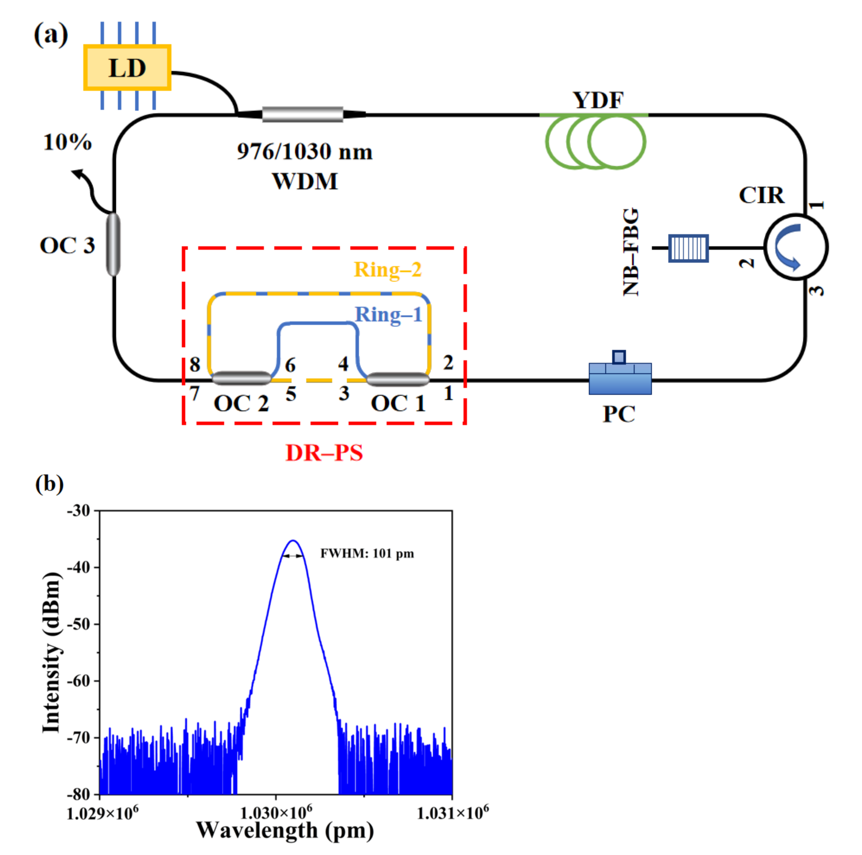
Figure 1a. The device is mainly composed of high Yb-doped fiber, circulator (CIR), high reflectivity Narrow Band-Fiber Bragg Grating (NB-FBG), and two 2 × 2 optical couplers (OC1 and OC2, coupling ratios of 90:10) to form DR-PS. A 976 nm semiconductor laser (LD) is used to couple the pump light into the resonant cavity through a 976/1030 nm wavelength division multiplexer to pump a 1 m long high Yb-doped fiber (YDF, LIEKKIYb1200-4/125, with an absorption coefficient of 516.15 dB/m at 976 nm). The maximum output power of the pump source is 550 mW. The active fiber is connected to the 1 port of the circulator, and the circulator can ensure that the signal light can only be transmitted in one direction. The NB-FBG (central wavelength is 1030.09 nm, 3-dB bandwidth is 101 pm, reflectivity >96%) is placed at port 2 of the ring cavity to roughly select the longitudinal mode of the laser and determine the central wavelength, as shown in
Figure 1b. The high reflectivity of NB-FBG can effectively reduce the transmission loss in the cavity. DR-PS is used for fine mode selection, and then DR-PS is connected with a 1 × 2 coupler (OC3). The 90% port of the coupler OC3 is connected to one end of the WDM to form a single-frequency fiber laser ring cavity structure, and the 10% port of the coupler is used to detect the output single-frequency laser. The polarization state of the signal light in the cavity is adjusted by properly adjusting the Polarization Controller (PC) placed between the CIR and the passive subcavity to achieve the best SLM operation.
In order to obtain Single Frequency (SF) operation, NB-FBG and DR-PS are needed to form a high-precision mode filter for mode selection. As shown in the red dotted line frame, OC1 and OC2 form two double-coupler fiber rings (Ring-1 and Ring-2) nested with each other to form a passive composite double-ring cavity (DR-PS). DR-PS is inserted between PC and OC3. The input beam is injected from port 1 of OC1, and 90% of the output beam through port 3 of OC1 enters port 5 of OC2, while 10% of the output beam through port 4 directly enters port 6 of OC2. For beams passing through OC2, 90% of the output beam from port 8 of OC2 is fed back to port 2 of OC1. A 10% beam through port 7 of OC2 is then used as the output of the DR-PS. The length of the main cavity of the laser is about 9.5 m, and the corresponding longitudinal mode frequency interval is about 21.8 MHz.
The reflection bandwidth of the NB-FBG used in the resonator is about 28.27 GHz at the wavelength of 1030 nm, which allows approximately ~1296 longitudinal modes to oscillate in the resonant cavity, which is not sufficient to suppress multiple longitudinal mode oscillations in the cavity. Therefore, we use NB-FBG as the initial longitudinal mode selection device, DR-PS as the longitudinal mode fine selection device, Ring-1 (blue line in
Figure 1) and Ring-2 (yellow dotted line in
Figure 1) in DR-PS correspond to two subring cavities with different cavity lengths, respectively. The different cavity lengths correspond to different free spectral ranges (FSR). The FSR of Ring-1 with a length of 1.47 m is about 138 MHz, and the FSR of Ring-2 with a length of 0.49 m is about 416 MHz, which can be calculated from the following equation:
where
is the speed of light in vacuum,
is the effective refractive index of the Yb-doped fiber, and
L is the length of the cavity corresponding to the cavity length of the subring cavity. According to the Vernier effect principle [
19], the effective FSR of the composite double-ring cavity is the least common multiple of the FSR of the two subring cavities, which can be calculated by the following equation:
where
and
are mutually exclusive positive integers. In order for the DR-PS to select one longitudinal mode out of about 1296 to form a stable single-longitudinal mode oscillation, the effective free spectral range of the composite subring cavity formed by the DR-PS must be larger than the reflection bandwidth of the NB-FBG. It is calculated that the
of the composite double-ring subcavity is greater than 28.27 GHz. This requires the long subcavity (Ring-1) of the composite subcavity to act as a high-precision mode filter to ensure that there is only one longitudinal mode oscillation in the 3-dB passband bandwidth of the transmission peak. Thus, the laser can only produce single-longitudinal mode oscillations in the resonant cavity if the passband conditions of the main cavity, the double-ring passive subcavity and the NB-FBG are met simultaneously. At this point, all longitudinal modes are suppressed except for the output signal. The mode selection schematic is shown in
Figure 2.
Next, we simplified the model of the DR-PS, which can be reduced to a double-OC nested fiber ring model, as shown in
Figure 3. We derive the transfer function of the fiber ring model and simulate its filtering characteristics in detail.
The Jones matrix theory of the coupler is used to derive the transfer function of the transmittance curve of its dual-OC fiber ring model as [
20]:
where
is the coupling ratio of the coupler,
is the transmission loss of the coupler,
is the time delay corresponding to the red line in the figure,
is the time delay corresponding to the blue line in the figure, and the total time delay is
, where
is the angular frequency of the light, so
, where
is the frequency of the light in the fiber,
is the cavity length of the subring cavity. The 3-dB bandwidth of the transmission peak is:
where
and
are the maximum and minimum values of the transmittance curve in one cycle, respectively. Bringing
and
into Equation (3), the 3-dB bandwidth of the transmittance peak can be obtained as:
where
and
are the frequency values corresponding to
and
of the fiber ring transfer function for one cycle, respectively. The DR-PS is simulated under different simulation conditions, and the results are shown in
Figure 4. Firstly, the transmittance curves corresponding to the length of the subring cavity under the conditions of 0.5 m, 1 m, 1.5 m, and 2 m are simulated in detail. It can be seen that the FSR gradually decreases with the increase of the length, and the 3 dB bandwidth corresponding to the transmittance curve is further narrowed. The length required for the experiment is obtained by fine adjustment of the parameters, as shown in
Figure 4a. Through parameter simulation, we determined that Ring-1 (blue line) corresponds to the transmittance curve formed by a 1.47 m long subring cavity to form a narrow passband bandwidth for filtering. Ring-2 (red line) corresponds to the transmittance curve formed by the 0.49 m short subring cavity, which can significantly expand the FSR, as shown in
Figure 4b. Next, the length of the subring cavity is kept constant. By changing the coupling ratio of the OC, it can be seen that the transmission peak is continuously narrowed when the coupling ratio increases and the linewidth of the laser can be further narrowed, as shown in
Figure 4c. Therefore, we chose a 90:10 fiber coupler in the experiment to obtain a narrower 3 dB bandwidth, so that 90% of the light returns to the subring cavity, forming a narrow-band interference and suppressing the MLM oscillation in the cavity. Through the above length and output coupling, it can be calculated that the Ring-1 subcavity in DR-PS has an ultra-narrow 3 dB bandwidth, which satisfies the longitudinal mode spacing of the main cavity between 1 and 2 times to ensure SLM operation. If the transmission bandwidth is too narrow or too wide, the laser will be susceptible to environmental changes, resulting in instability, such as MLM and mode hopping.
3. Experimental Results and Discussion
In the experiments, all experimental operations were carried out at constant laboratory temperature during which no temperature compensation devices or vibration isolation techniques were used. The proposed YDFL outputs a laser with high OSNR, ultra-narrow linewidth, and high stability as shown below.
The SLM output of YDFL is detected by using a scanning Fabry–Pérot Interferometer (FPI, Thorlabs-SA200-8B) to detect the output longitudinal mode characteristics. The free spectral range and resolution of this scanning F-P interferometer were 1.5 GHz and 7.5 MHz, respectively. The laser reached the threshold power at a pump power of 80 mW, at which point a laser output was detected and the pump power was continuously increased. The output longitudinal model of the laser was detected when the pump power was 200 mW, as shown in
Figure 5. It can be seen in
Figure 5a that in the removal of the DR-PS state, only the NB-FBG is filtered in the whole cavity, and the NB-FBG is not sufficient to suppress the multi-longitudinal mode oscillation, so the laser output is multi-longitudinal mode state. When the DR-PS is added to the cavity, the gain and loss in the cavity are balanced through continuous fine tuning of the PC, resulting in a stable single-longitudinal mode oscillation output in the resonant cavity of the fiber laser, as shown in
Figure 5b. Thus, we can maintain a stable single-longitudinal mode output as observed by long time operation, and the proposed DR-PS plays a key role in the suppression of MLM.
For the output spectrum and short-term stability of the laser, we measured it with an Optical Spectrum Analyzer (OSA, AQ6370C), as shown in
Figure 6. When the resolution is 0.02 nm (the real resolution is 0.034 nm) and the pump power is 240 mW, the single-frequency laser output spectrum is measured.
Figure 6a shows that the central wavelength of the output spectrum is 1030.052 nm, and the optical signal-to-noise ratio is 73 dB. In order to prove the short-term stability of the laser, we keep the other parts of the laser unchanged and repeat the OSA scanning spectrum 30 times at 1 min intervals. It can be seen from
Figure 6b that the center wavelength and power of the output laser have no obvious fluctuation, indicating that the laser is in a stable SLM operation state at room temperature.
Figure 7a shows the variation of OSNR measured by OSA with increasing pump power. We gradually increase the pump power for observation. It can be seen that the signal-to-noise ratio of YDFL always maintains an upward trend. In the pump range of 0~240 mW, OSNR increases rapidly with the increase of pump power. When the pump power continues to increase, it reaches about 74 dB at 300 mW. OSNR gradually reaches a saturated state. When the pump power continues to increase, OSNR rises very slowly and does not change significantly. The proposed YDFL has excellent OSNR performance, which is mainly due to the excellent mode selection ability of the designed DR-PS.
Next, we measured the output power of a single-frequency laser at 10% of the OC3 output port.
Figure 7b shows the relationship between the pump power and output power of a single-frequency fiber laser. The threshold power of the laser is 80 mW and its slope efficiency is 1.38%. The main reason for the low slope efficiency is that the double-ring passive subcavity retains only 10% of the light in the main cavity. In the experimental setup structure, the intracavity devices introduce too much insertion loss, and solder joints have mode field mismatch loss, which will also lead to a low slope efficiency of the laser.
In addition, we tested the long-term stability of the laser output through the OSA, and monitored the output center wavelength and power stability of the single-frequency laser while keeping the pump power constant at 250 mW. As shown in
Figure 8, the data acquisition is performed every 2 min over a time range of 120 min. The fluctuation range of the output wavelength and power of the laser is in the range of 0.008 nm and 0.19 dB within 120 min, indicating that the built laser has good long-term stability. This fluctuation is mainly due to small fluctuations caused by the experimental environmental conditions.
Finally, the linewidth of the single-frequency laser output is measured by a self-built linewidth measurement device based on the delayed self-heterodyne method [
21]. The length of the delay fiber in the delay self-heterodyne method device is 30 km. The beat frequency signal is shifted to 150 MHz by using the acousto-optic frequency shifter (Gooch S-M150-0.4C2G-3-F2S), and the beat frequency signal detected by the photodiode detector (DET08CFC/M) is collected by the spectrum analyzer (KEYSIGHT N9000B).
Figure 9 shows the linewidth of the single-frequency laser output when the pump power is 250 mW. The center frequency is set to 150 MHz, the span is 260 kHz, and the resolution is 36 Hz. The laser measures the original spectral data points (black points) by a delayed self-heterodyne device and then fits the curve (red line) by Lorentz fitting. It can be seen from
Figure 9 that the linewidth at 20 dB below the peak of the beat signal is 7.11 kHz, and the corresponding spectral FWHM is 355 Hz, which belongs to the ultra-narrow linewidth laser of the hundred Hz level. However, considering that the 1/f noise generated by the 30 km delay fiber at the center frequency will inevitably lead to the broadening effect of the fitting curve, the actual linewidth may even be smaller than the measured linewidth [
22].


