Abstract
A wavelength-tunable single-longitudinal-mode (SLM) narrow-linewidth thulium/holmium co-doped fiber laser (THDFL) was developed in this study. The lasing wavelength was determined by combining a phase-shifted fiber Bragg grating (PS-FBG) and a uniform FBG (UFBG). SLM oscillation was achieved by incorporating a dual-coupler ring filter with the PS-FBG. At a pump power of 2.0 W, the THDFL exhibited excellent SLM lasing performance with a stable optical spectrum. It operated at an output wavelength of ~2050 nm with an optical signal-to-noise ratio of >81 dB, an output power fluctuation of 0.15 dB, a linewidth of 8.468 kHz, a relative intensity noise of ≤−140.32 dB/Hz@≥5 MHz, a slope efficiency of 2.15%, and a threshold power of 436 mW. The lasing wavelength tunability was validated experimentally by stretching the PS-FBG and UFBG simultaneously. The proposed THDFL had significant potential for application in many fields, including free-space optical communication, LiDAR, and high-precision spectral measurement.
1. Introduction
The 2 μm band laser exhibits both a high absorption window and a high transmission window in atmospheric transmission. The spectral region near 2050 nm contains many absorption lines of important atmospheric gases such as H2O and CO2 [1]. The atmospheric transmissivity of lasers near 2040 nm reaches as high as 80% [2]. Eye-safe fiber lasers operating near 2 μm, with strong absorption in animal/human tissues and minimal damage to the retina, are extensively used in medical fields [3,4,5], generating significant research interest. The single-longitudinal-mode (SLM) thulium/holmium co-doped fiber laser (THDFL), which is characterized by low noise, narrow linewidth, high coherence, electromagnetic immunity, and an all-optical fiber structure, shows tremendous potential in various fields including high-resolution spectroscopy, coherent optical communication, LiDAR, and materials processing [6,7,8,9,10].
Several configurations of THDFLs enable SLM operation, such as distributed feedback (DFB) [11] and distributed Bragg reflector (DBR) [12,13] structures with ultrashort cavities, as well as conventional linear or ring compound cavities with ultra-narrow-band filters. The amplified spontaneous emission (ASE) of thulium-doped fiber (TDF) or THDF falls within the range of 1.7–2.1 μm, with a center wavelength near 1900 nm [14,15,16]. DFB or DBR lasers require heavily rare-earth-doped fiber to achieve SLM oscillation near 2050 nm but suffer high relaxation oscillation noise, wide linewidth, and low Q-values. In contrast, ring-compound-cavity lasers, employing various functional devices to mitigate the spatial-hole-burning effect, can achieve narrow-linewidth SLM operation with a high stability and a high optical signal-to-noise ratio (OSNR). Commonly used optical filters include the Mach–Zehnder interferometer [17,18,19], Fabry–Pérot (F-P) filter [20,21], superimposed fiber Bragg grating (FBG) [22], chirped Moiré FBG [23,24], sampled FBG [25,26], multimode FBG [27], phase-shifted FBG (PS-FBG) [11,28,29], a ring cavity filter (RCF) [30,31,32,33], and a dynamic narrow-band filter based on an unpumped rare-earth-doped fiber saturable absorber (SA) [34,35,36]. The combination of a uniform FBG (UFBG) and a PS-FBG enabled narrow-band filtering with a stable performance, exhibiting a full-width at half-maximum (FWHM) of the transmission channel much narrower than that of the UFBG [28,29]. The RCF, functioning as a comb filter, offers advantages of high stability and low cost, with flexible control over its free spectrum range (FSR) and FWHM. Judiciously designing the RCF and integrating it with the PS-FBG may yield a high-performance SLM THDFL.
This paper presents a wavelength-tunable narrow-linewidth THDFL based on a PS-FBG and a dual-coupler ring (DCR) filter. The combination of the PS-FBG and a UFBG enables precise determination of the lasing wavelength and achieves narrow-band filtering. The DCR is introduced into the THDFL to increase the longitudinal-mode spacing and achieve SLM oscillation. The experimental results demonstrate the SLM lasing operation at a center wavelength of 2049.795 nm, an OSNR of 81.34 dB, and an output power of 30.7 mW when the pump power is 2.0 W. Detailed investigations on the stability of the optical spectrum and output power, SLM operation, linewidth, relative intensity noise (RIN), slope efficiency, and wavelength tunability are presented as well.
2. Experimental Setup and Principle
The configuration of the SLM THDFL, as shown in Figure 1, consisted of a 1567 nm pump laser with a maximum output power of 5 W, a 1550/2050 nm wavelength division multiplexer (WDM), a 1.6 m long THDF, a UFBG, a PS-FBG, a DCR (formed by two optical couplers, OC2 and OC3, both with a coupling ratio of 30:70) with a ring length of 0.6 m, a circulator, and a 20:80 optical coupler OC1. The THDFL output was extracted from the 20% port of the OC1. The PS-FBG and UFBG were used in combination to achieve narrow-band filtering based on the transmission channel of the PS-FBG. The UFBG, with a matched center wavelength, was introduced by the circulator to ensure unidirectional light oscillation in the THDFL. The lasing wavelength could be tuned by simultaneously stretching the PS-FBG and UFBG with a micro-displacement platform. The SLM lasing operation was achieved by combining the DCR and PS-FBG. The total cavity length of the THDFL was approximately 4.95 m, corresponding to a longitudinal-mode spacing of approximately 41.65 MHz. The OCs and WDM used in the setup were all fabricated by our research team.
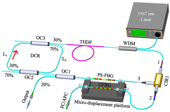
Figure 1.
SLM THDFL diagram. WDM: Wavelength division multiplexer; THDF: Tm-Ho co-doped fiber; DCR: Dual-coupler ring; CIR: Circulator; UFBG: Uniform fiber Bragg grating; PS-FBG: Phase-shifted FBG; OC: Optical coupler.
According to the coupled-mode theory, as a narrow-band reflecting filter, the reflectivity of the UFBG can be expressed as [37]:
where is the UFBG’s length, and is the mutual-coupling coefficient, which is calculated by:
where is the fringe visibility of the index change, is the wavelength, is the modulation depth, and is the auto-coupling coefficient, given by:
where denotes the phase chirp, is the transmission constant, is the center wavelength, is the nominal period, and is the effective refractive index of the single-mode fiber (SMF). The refractive index modulation of the UFBG is uniformly distributed along the z- axis; thus, .
The length of the phase mask was set to 20 mm in the experiment. The parameters mm, nm, and were used in the calculations. The reflection spectrum of the UFBG is marked with a blue curve in Figure 2a. The center wavelength is 2049.801 nm, the reflectivity is 99.05%, and the FWHM is 12.52 GHz.
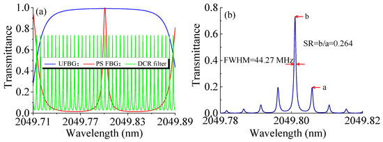
Figure 2.
(a) Simulated spectra of UFBG, PS-FBG, and DCR; (b) Spectrum obtained by multiplying three spectra in (a).
The PS-FBG, serving as a narrow-band filter, was fabricated using the occlusion method based on the phase mask technique. During the inscription process of a UFBG using ultraviolet light, a small occlusion segment was introduced in the exposure area of the phase mask. The absence of ultraviolet light radiation in the occlusion area led to a sudden change in the refractive index, forming the PS-FBG. Consequently, the PS-FBG could be considered as an F-P cavity composed of two UFBGs with the same center wavelength. The transmissivity could be calculated as follows [38]:
where , , and are the reflectivities of the UFBG1 and UFBG2; and is the effective length of the F-P cavity:
where is the length of the occlusion area, , and is the center wavelength.
In the calculation process, mm and other parameters were consistent with the UFBG simulation. The transmission spectrum of the PS-FBG was marked with a red curve in Figure 2a. The narrow-band transmission channel of the PS-FBG was located in the reflection envelop of the UFBG. The PS-FBG’s center wavelength was 2049.800 nm, the transmissivity was as high as 99.99%, and the FWHM was 406.26 MHz. The DCR filter’s transmission could be expressed as [39]:
where denotes electric field amplitudes; and dB are the coupling ratio and insertion loss of the OC2 and OC3, respectively; dB is the fusion splicing loss; dB/km is the fiber loss coefficient; and is the wave number in a vacuum. Prior to substituting the parameters expressed in decibel units into Equation (8), please note that they are initially converted into dimensionless values.
To achieve SLM lasing, it is necessary for the FSR of the DCR filter to be smaller than the FWHM of the PS-FBG. Additionally, the transmission FWHM of the DCR filter should ideally be less than twice the longitudinal-mode spacing of the oscillating cavity. In theory, the transmission spectrum of the DCR filter can be tailored using Equation (8) through careful adjustment of the DCR cavity length ( + ) and the cross-coupling ratios of OC2 and OC3. When the DCR’s length is 0.6 m ( m), the transmission spectrum is as marked with a green curve in Figure 2a. The FSR and FWHM are 344.15 MHz and 44.27 MHz, respectively. Figure 2b shows the composite filtering characteristics of the UFBG, PS-FBG, and DCR. The center wavelength is 2049.801 nm, the FWHM is 44.27 MHz, and the suppression ratio (SR) is 0.264. Therefore, considering the mode spacing of ~41.65 MHz of the main cavity, the proposed THDFL can (theoretically) achieve SLM operation.
Both the UFBG and PS-FBG utilized in this study were custom-made commercially. To characterize their filtering properties, a broadband light source (NKT, Photonics A/S, SUPERK EVO, Copenhagen, Denmark) and an optical spectrum analyzer (OSA, Yokogawa AQ6375B, Tokyo, Japan) with a resolution of 0.05 nm and a data sampling interval of 0.003 nm were employed, as shown in Figure 3. The measurements revealed that the UFBG had a center wavelength and a FWHM of 2049.793 nm and 18.85 GHz, respectively. The PS-FBG exhibited a narrow-band transmission channel centered at 2049.816 nm. The experimental results were consistent with the simulation results for both devices. However, due to the limited resolution of the OSA, accurate measurement of the narrow-band transmission channel’s FWHM of the PS-FBG was not possible. As shown in Figure 3b, the UFBG achieved a transmission depth of 15.56 dB, corresponding to a reflectivity of 97.79%. The high reflectivity of the UFBG contributed to minimizing cavity losses and facilitated the construction of an SLM fiber laser with a high Q value, as well as the generation of laser output with a high OSNR.
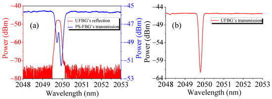
Figure 3.
(a) Measured reflection spectrum of UFBG and transmission spectrum of PS-FBG; (b) Measured transmission spectrum of UFBG.
3. Experimental Results and Discussion
The proposed THDFL system was constructed on a metal optical table and operated at room temperature. Stable lasing oscillation was achieved with a pump power of 2.0 W. The optical spectrum of the THDFL was captured by the OSA, as shown in Figure 4a. The lasing wavelength was 2049.795 nm with an OSNR exceeding 81.34 dB. No evident amplified spontaneous emission (ASE) was observed in the range as wide as 1950–2150 nm (Figure 4b), indicating the effective reflection filtering property of the UFBG. This characteristic contributed to the construction of fiber lasers with high OSNR and low noise.
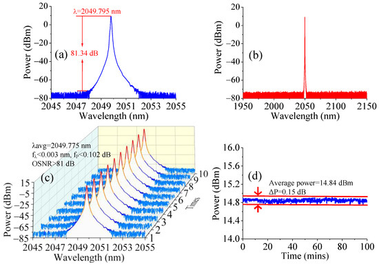
Figure 4.
(a) Output spectrum of THDFL in 2045–2055 nm range; (b) Spectrum measured in 1950–2150 nm range; (c) 10 repeated lasing spectrum scans; (d) Output power stability measured with power meter at data sampling rate of 1 Hz.
To investigate the lasing stability of the THDFL, the output spectrum was monitored using the OSA, and the output power was measured with a power meter (Thorlabs, S405C, Newtown, NJ, USA) for approximately 100 min. The resulting spectra are shown in Figure 4c, where the lasing wavelength was centered at 2049.775 nm (λavg), the wavelength fluctuation (fλ) was less than 0.003 nm, the power fluctuation (fp) was less than 0.102 dB, and the OSNR was consistently higher than 81 dB. The output power stability was analyzed using a power meter with a data sampling rate of 1 Hz, as shown in Figure 4d. The average power was measured to be 14.84 dBm, with power fluctuation as low as 0.15 dB. The THDFL thus showed excellent output stability in terms of both the laser spectrum and output power.
The longitudinal-mode characteristic of the THDFL was investigated using a scanning F-P interferometer (Thorlabs, SA200-18C, Newtown, NJ, USA) with an FSR of 1.5 GHz and a resolution of 7.5 MHz, as shown in Figure 5; the red sawtooth wave was the driving voltage signal of the interferometer, and the blue curve was the lasing mode signal. Within a voltage scanning period, in which the F-P interferometer could scan more than one FSR, there were only two lasing modes captured, indicating stable SLM operation of the THDFL.
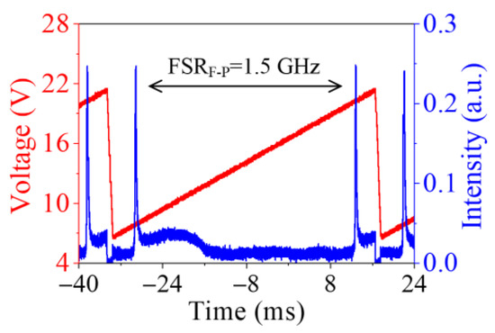
Figure 5.
Longitudinal-mode characteristic measured by scanning F-P interferometer.
The SLM operation of the THDFL was further verified using the self-homodyne method. The radio frequency (RF) beating spectrum was measured using a 1 GHz photodetector (PD) and an RF electrical spectrum analyzer (ESA, Keysight N9010A, Santa Rosa, CA, USA), as shown in Figure 6a. No distinct beating signal was captured in an approximately 10 min observation period using the maximum-hold (MH) mode of the ESA, indicating that the THDFL maintained stable SLM operation.
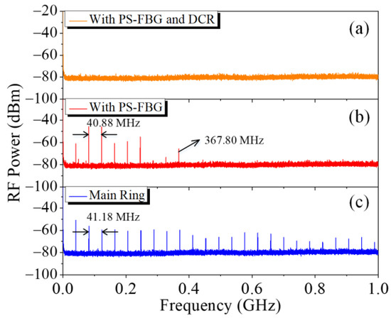
Figure 6.
RF spectra of THDFL measured by ESA with maximum-hold mode: (a) PS-FBG and DCR; (b) DCR replaced with SMF; (c) DCR and PS-FBG both replaced by SMFs with self-homodyne method.
The SLM selection capability of the DCR filter was also confirmed by replacing it with an identically sized SMF in the laser cavity. The beating spectrum is shown in Figure 6b. Multiple beating signals were clearly observed, indicating that the THDFL was operating in a multi-longitudinal-mode (MLM) state. The spacing between adjacent peaks was approximately 40.88 MHz, corresponding to a longitudinal-mode spacing of 40.88 MHz. Notably, the maximum beating signal frequency was 367.80 MHz, suggesting that the FWHM of the PS-FBG should have been ~367.80 MHz.
Finally, when both the PS-FBG and the DCR filter were removed from the laser cavity, the beating spectra of the laser output were measured as shown in Figure 6c. The longitudinal-mode spacing was ~41.18 MHz. Many clearly observable beating signals remained when the frequency was higher than 367.8 MHz. These results altogether suggested that the DCR and PS-FBG had excellent filtering characteristics, contributing to stable SLM operation of the THDFL.
Due to the high transmission loss of SMF in the long-wavelength region (2050 nm) of nearly 20 dB/km, the commonly used delayed self-heterodyne measurement system with an ultra-long SMF delay line was not suitable for analyzing the linewidth characteristics of the THDFL [35]. The double-beam heterodyne method for linewidth measurement required an ultra-narrow linewidth reference laser [40]. The Brillouin fiber laser had a linewidth narrowing effect to its pump laser [41,42]. There was a Brillouin frequency shift between the Brillouin laser and its pump laser. Therefore, the double-beam heterodyne method could be used to measure the linewidth of the THDFL by utilizing a reference Brillouin laser pumped by the amplified THDFL.
The SLM THDFL output was amplified with a self-built Thulium doped fiber amplifier (TDFA) system to achieve a high-power output, as shown in Figure 7. A 10% output was extracted through a fiber coupler, OC4 (10:90), to monitor the performance of the SLM THDFL, whereas the remaining 90% laser was amplified by the TDFA system after passing through an isolator. The primary amplifying stage consisted of a 793 nm laser diode (LD1) with a maximum output power of 12 W, a (2 + 1) × 1 fiber combiner (FC1), a 2.6 m Thulium-doped fiber (TDF1, Nufern, SM-TDF-10P/130-M, East Windsor, CT, USA), and a self-made cladding power stripper (CPS1). The secondary amplifying stage included a 793 nm LD2 with a maximum output power of 30 W, a (2 + 1) × 1 FC2, a 3.0 m TDF2, and a CPS2. An additional isolator was introduced between the two stages to ensure unidirectional laser transmission.
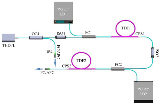
Figure 7.
Self-built TDFA system. LD: Laser diode; ISO: Isolator; TDF: Tm-doped fiber; CPS: Cladding power stripper.
The evolution of the TDFA system’s output power as a function of the LD2’s pump power was measured using a power meter with LD1 pump power of 5.0 W, as shown in Figure 8. At a LD2 pump power of 20.0 W, the output power reached 4.7 W; the power meter’s damage threshold was 5.0 W. The spectrum of the amplified laser was measured using the OSA, as shown in Figure 8b, where the power was attenuated before the OSA. The OSNR was 43.75 dB in this case, and there was no self-excited oscillation at the maximum gain near 1970 nm, indicating satisfactory performance of the TDFA system.
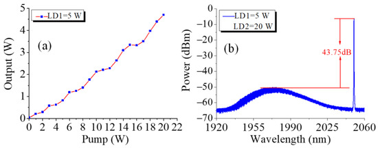
Figure 8.
(a) Output power of TDFA system as a function of pump power from LD2; (b) Output spectrum of TDFA system at pump power of 20 W from LD2.
The amplified laser from the TDFA system served as the pump source for the Brillouin laser. The setup of the Brillouin-laser-based laser linewidth measurement system is shown in Figure 9. The output of the TDFA system was directed into Brillouin laser cavity through a circulator (CIR2). A 15 m long SMF was used as the Brillion gain fiber, and the Brillouin laser was extracted from the 30% port of a coupler OC5 (30:70). A drop-in polarization controller was used to control the polarization state for stable lasing. The length of the Brillouin laser cavity was ~16.5 m, corresponding to a longitudinal-mode spacing of approximately 12.5 MHz. In the 2 μm wavelength band, the Brillouin gain envelop of the commonly used SMF was ~15.00 MHz [41], which theoretically allowed for SLM operation of the Brillouin laser.
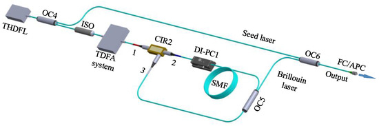
Figure 9.
Brillouin-laser-based laser linewidth measurement system. DI-PC: Drop-in polarization controller.
By setting the pump power of the LD1 and LD2 to 5.0 W and 9.0 W, respectively, resulting in an amplified laser power of 1.76 W, the Brillouin output was achieved with a lasing wavelength of 2050.011 nm and an OSNR of 63.78 dB (Figure 10a). The RF beating spectrum of the Brillouin laser was measured using the self-homodyne method with a 1 GHz PD and an electrical spectrum analyzer (ESA), as shown in Figure 10b. No beating signal was captured over a ~10 min measurement duration, indicating stable SLM oscillation of the Brillouin laser.
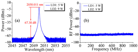
Figure 10.
(a) Brillouin laser output spectrum; (b) Longitudinal-mode characteristic of Brillouin laser.
The linewidth of the Brillouin laser was narrower than that of the pump laser [41,42], and a linewidth compression factor of 1/18 could be achieved according to the theory described in [43]. Thus, it was possible to determine the linewidth of the THDFL by analyzing the RF signal obtained from beating the Brillouin laser and its pump laser. As a lasing linewidth broadening effect could be caused by phase noise and self-phase modulation in the TDFA system [44] the 10% output laser of the THDFL from OC4 was combined with the Brillouin laser at OC6 to obtain the RF beating signal in our measurement setup, which was then measured using a 12.5 GHz PD and an ESA. Figure 11 displays the measurement data and corresponding Lorentz fitting curve. The 20 dB bandwidth of the spectrum was 168.36 kHz. Accordingly, by applying a calculation factor of 1/20, the linewidth of the THDFL was calculated to be 8.468 kHz.
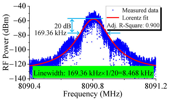
Figure 11.
Linewidth measurement result of THDFL with beating output and Brillouin laser.
The RIN spectrum could characterize instantaneous power fluctuations of the THDFL. This spectrum was measured using a 400 MHz PD, an oscilloscope (Tektronix, TDS2024C, Beaverton, OR, USA), and an ESA. The oscilloscope captured the direct voltage of the PD’s output. The results are shown in Figure 12, where a frequency over 5 MHz yielded an RIN of the THDFL of ≤−140.32 dB/Hz. The relaxation oscillation peak was close to 108.19 kHz, as shown in the inset. The small noise signal near 320.89 kHz was mainly caused by the measurement system.
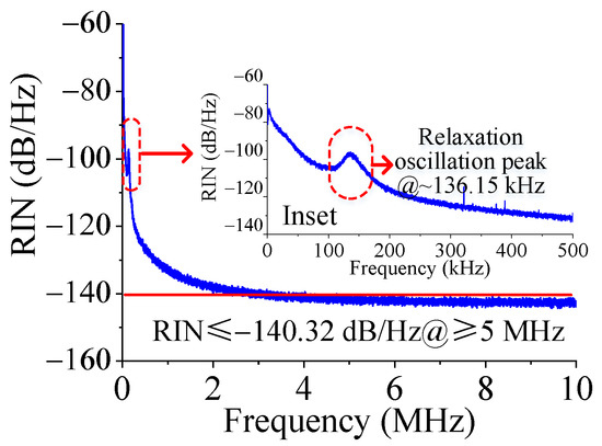
Figure 12.
RIN spectrum measured in 0–10 MHz range; RIN spectrum measured in 0–500 kHz range (inset).
The spectra and longitudinal-mode characteristics of the THDFL under various pump power levels were examined to further investigate its performance. As shown in Figure 13a, the OSNR gradually increased as the pump power increased, whereas the center lasing wavelength of the THDFL showed a fluctuation (fλ) ≤0.021 nm due to the different thermal effects under different pump power levels. The SLM characteristics of the THDFL were further confirmed using the self-homodyne method while increasing the pump power, as shown in Figure 13b. There was no beating signal captured in an approximately 10 min measurement period, indicating that the THDFL maintained stable SLM operation under different pump power levels and further confirming the favorable characteristics of the PS-FBG and DCR filters.
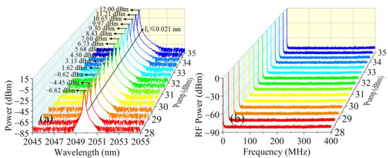
Figure 13.
Measured (a) laser output spectra and (b) SLM characteristics under different THDFL pump power levels.
The laser output power was analyzed at different pump power levels using a power meter. Figure 14a shows the measured data and linear fitted curve. The laser showed a slope efficiency of 2.15% and threshold power of 436 mW. The output power, reaching 55.1 mW at a pump power of 3.16 W, had not yet reached saturation. To prevent potential damage to the devices in the laser cavity due to high pump power, the maximum output power was not measured. When the pump power was 1.0 W and the direction of the signal light was opposite to the direction of the pump light, the ASE of the 1.6 m gain THDF at 2049.792 nm was 34.11 dB lower than that at the maximum gain wavelength (1850 nm) (Figure 14b). This indicated that the maximum gain wavelength differed significantly from the output wavelength of our THDFL. Additionally, the insertion loss of all devices used in the 2 μm band was considerable. These factors contributed to the low slope efficiency of the THDFL.
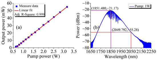
Figure 14.
(a) Output power of THDFL as a function of pump power; (b) ASE of THDF at pump power of 1.0 W.
The PS-FBG and UFBG were clamped onto the micro-displacement platform, as shown in Figure 1, then the wavelength-tunability of the THDFL was investigated by tuning the right knob of the micro-displacement platform to stretch the PS-FBG and UFBG horizontally. The operating wavelength of the THDFL was tuned from 2049.962 nm to 2050.397 nm with a tunable range of ~0.435 nm, as shown in Figure 15, which performed a groundbreaking demonstration of the feasibility of laser wavelength tuning in a fiber laser through the simultaneous stretching of both the PS-FBG and the UFBG, validating its potential for practical applications. The OSNR of the THDFL within the wavelength-tunable range was no less than 79.5 dB. A larger wavelength-tuning process was not performed, however, to avoid damaging the PS-FBG and UFBG. Achieving a large tunable range will be our focus in future work.
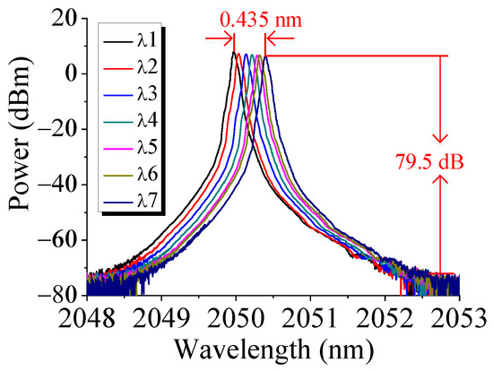
Figure 15.
Output spectra of THDFL with wavelength-tunable range of 0.435 nm.
4. Conclusions
A wavelength-tunable SLM narrow-linewidth THDFL was developed and demonstrated in this study. A combination of PS-FBG and UFBG was utilized to achieve narrow-band filtering, with an additional DCR that enabled SLM oscillation. SLM operation was achieved under a pump power of 2.0 W, then the output performance of the setup was investigated thoroughly. The THDFL exhibited an OSNR of >81 dB with a highly stable optical spectrum, an output power fluctuation of ≤0.15dB, a linewidth of <8.468 kHz, an RIN of ≤−140.32 dB/Hz@≥5 MHz, a slope efficiency of 2.15%, and a threshold power of 436 mW.
The THDFL’s output power was amplified to achieve a high-power output of 4.7 W, which was then used as a pump source for Brillouin SLM oscillation near 2050 nm. The THDFL achieved stable SLM operation at different pump power levels as well. By tuning the PS-FBG and FBG, the wavelength-tunable range was approximately 0.435 nm in the THDFL.
The proposed SLM narrow-linewidth THDFL featured a simple structure and excellent performance. With professional temperature compensation and vibration isolation packaging, it would exhibit even better output characteristics. This technology shows considerable potential for application in wavelength-division-multiplexing free-space optical communication, laser radar, atmospheric trace gas detection, and other fields.
Author Contributions
Conceptualization, T.F and F.Y.; methodology, T.F., Q.L., and X.S.Y.; writing—original draft preparation, D.L. and S.G.; writing—review and editing, T.F. and S.W. All authors have read and agreed to the published version of the manuscript.
Funding
This work was supported by the National Natural Science Foundation of China (Grant Nos. 61975049, 61827818), the Hebei “333 talent project” (A202101010), the Science and Technology Research Project in Colleges and Universities of Hebei Province (ZD2022138), the Hebei Provincial Innovation Ability Promotion Project (20542201D), and the Interdisciplinary Research Program of Natural Science of Hebei University (DXK202201).
Institutional Review Board Statement
Not applicable.
Informed Consent Statement
Not applicable.
Data Availability Statement
The data presented in this study is available from the corresponding author upon reasonable request.
Conflicts of Interest
The authors declare no conflict of interest.
References
- Taczak, T.M.; Killinger, D.K. Development of a tunable, narrow-linewidth, cw 2.066-μm Ho: YLF laser for remote sensing of atmospheric CO2 and H2O. Appl. Opt. 1998, 37, 8460–8476. [Google Scholar] [CrossRef]
- McComb, T.S.; Sims, R.A.; Willis, C.C.C.; Kadwani, P.; Sudesh, V.; Shah, L.; Richardson, M. High-power widely tunable thulium fiber lasers. Appl. Opt. 2010, 49, 6236–6242. [Google Scholar] [CrossRef]
- Jihong, G.; Qing, W.; Yinwen, L.; Shibin, J. Development of eye-safe fiber lasers near 2 μm. IEEE J. Sel. Top. Quantum Electron. 2014, 20, 150–160. [Google Scholar] [CrossRef]
- Tendean, M.; Mambu, T.D.B.; Tjandra, F.; Panelewen, J. The use of thulium-doped fiber laser (TDFL) 1940 nm as an energy device in liver parenchyma resection, a-pilot-study in Indonesia. Ann. Med. Surg. 2020, 60, 491–497. [Google Scholar] [CrossRef]
- Janeczek, M.; Rybak, Z.; Lipińska, A.; Bujok, J.; Czerski, A.; Szymonowicz, M.; Dobrzyński, M.; Swiderski, J.; Żywicka, B. Local effects of a 1940 nm thulium-doped fiber laser and a 1470 nm diode laser on the pulmonary parenchyma: An experimental study in a pig model. Materials 2021, 14, 5457. [Google Scholar] [CrossRef]
- Fried, N.M. Thulium fiber laser lithotripsy: An in vitro analysis of stone fragmentation using a modulated 110-watt thulium fiber laser at 1.94 μm. Lasers Surg. Med. 2005, 37, 53–58. [Google Scholar] [CrossRef]
- Cariou, J.-P.; Augere, B.; Valla, M. Laser source requirements for coherent lidars based on fiber technology. Comptes Rendus Phys. 2006, 7, 213–223. [Google Scholar] [CrossRef]
- Koch, G.; Beyon, J.; Barnes, B.; Petros, M.; Yu, J.; Amzajerdian, F.; Kavaya, M.; Singh, U. High-energy 2 μm Doppler lidar for wind measurements. Opt. Eng. 2007, 46, 116201. [Google Scholar] [CrossRef]
- Tao, M.; Tao, B.; Hu, Z.; Feng, G.; Ye, X.; Zhao, J. Development of a 2 μm Tm-doped fiber laser for hyperspectral absorption spectroscopy applications. Opt. Express 2017, 25, 32386–32394. [Google Scholar] [CrossRef]
- Lahyani, J.; Le Gouet, J.; Gibert, F.; Cezard, N. 2.05-μm all-fiber laser source designed for CO2 and wind coherent lidar measurement. Appl. Opt. 2021, 60, C12–C19. [Google Scholar] [CrossRef]
- Walasik, W.; Traore, D.; Amavigan, A.; Tench, R.E.; Delavaux, J.-M.; Pinsard, E. 2-μm narrow linewidth all-fiber DFB fiber Bragg grating lasers for Ho- and Tm-doped fiber-amplifier applications. J. Light. Technol. 2021, 39, 5096–5102. [Google Scholar] [CrossRef]
- Guan, X.; Yang, C.; Gu, Q.; Wang, W.; Tan, T.; Zhao, Q.; Lin, W.; Wei, X.; Yang, Z.; Xu, S. 55 W kilohertz-linewidth core- and in-band-pumped linearly polarized single-frequency fiber laser at 1950 nm. Opt. Lett. 2020, 45, 2343–2346. [Google Scholar] [CrossRef] [PubMed]
- Fang, S.; Zhang, Z.; Yang, C.; Lin, W.; Cen, X.; Zhao, Q.; Feng, Z.; Yang, Z.; Xu, S. Gain-switched single-frequency DBR pulsed fiber laser at 2.0 μm. IEEE Photonics Technol. Lett. 2022, 34, 255–258. [Google Scholar] [CrossRef]
- Khamis, M.A.; Ennser, K. Enhancement on the generation of amplified spontaneous emission in thulium-doped silica fiber at 2 μm. Opt. Commun. 2017, 403, 127–132. [Google Scholar] [CrossRef]
- Miluski, P.; Kochanowicz, M.; Żmojda, J.; Dorosz, D.; Łodziński, M.; Baranowska, A.; Dorosz, J. Eye safe emission in Tm3+/Ho3+ and Yb3+/Tm3+ co-doped optical fibers fabricated using MCVD-CDS system. Opt. Mater. 2020, 101, 109711. [Google Scholar] [CrossRef]
- Zhou, D.; Bai, X.; Zhou, H. Preparation of Ho3+/Tm3+ co-doped lanthanum tungsten germanium tellurite glass fiber and its laser performance for 2.0 μm. Light-Sci. Appl. 2017, 7, 44747. [Google Scholar] [CrossRef]
- Shi, C.; Fu, S.; Shi, G.; Sun, S.; Sheng, Q.; Shi, W.; Yao, J. All-fiberized single-frequency silica fiber laser operating above 2 μm based on SMS fiber devices. Optik 2019, 187, 291–296. [Google Scholar] [CrossRef]
- Guo, Y.; Yan, F.; Feng, T.; Qin, Q.; Zhang, L.; Guan, B.; Han, W.; Bai, Z.; Zhou, H.; Suo, Y. Stable multi-wavelength thulium-doped fiber laser with two cascaded single-mode-four-mode-single-mode fiber interferometers. IEEE Access 2021, 9, 1197–1204. [Google Scholar] [CrossRef]
- Soltanian, M.R.; Ahmad, H.; Khodaie, A.; Amiri, I.S.; Ismail, M.F.; Harun, S.W. A stable dual-wavelength thulium-doped fiber laser at 1.9 μm using photonic crystal fiber. Light-Sci. Appl. 2015, 5, 14537. [Google Scholar] [CrossRef]
- Zhang, K.; Peter, Y.-A.; Rochette, M. Chalcogenide Fabry–Perot fiber tunable filter. IEEE Photonics Technol. Lett. 2018, 30, 2013–2016. [Google Scholar] [CrossRef]
- Camarillo-Aviles, A.; Jauregui-Vazquez, D.; Estudillo-Ayala, J.M.; Hernandez-Escobar, E.; Sierra-Hernandez, J.M.; Pottiez, O.; Duran-Sanchez, M.; Ibarra-Escamilla, B.; Bello-Jimenez, M. Stable multi-wavelength thulium-doped all-fiber laser incorporating a multi-cavity Fabry–Perot filter. IEEE Photonics J. 2019, 11, 7105307. [Google Scholar] [CrossRef]
- Guo, Y.; Yan, F.; Feng, T.; Qin, Q.; Han, W.; Cheng, D.; Yu, C.; Yang, D.; Zhou, H.; Suo, Y. Wavelength-switchable single-longitudinal-mode thulium-doped fiber laser at 2.05 µm using a superimposed fiber Bragg grating. Infrared Phys. Technol. 2022, 122, 104058. [Google Scholar] [CrossRef]
- Yan, F.; Peng, W.; Liu, S.; Feng, T.; Dong, Z.; Chang, G.-K. Dual-wavelength single-longitudinal-mode Tm-doped fiber laser using PM-CMFBG. IEEE Photonics Technol. Lett. 2015, 27, 951–954. [Google Scholar] [CrossRef]
- Wang, L.; Shen, Z.; Feng, X.; Li, F.; Cao, Y.; Wang, X.; Guan, B.-O. Tunable single-longitudinal-mode fiber laser based on a chirped fiber Bragg grating. Opt. Laser Technol. 2020, 121, 105775. [Google Scholar] [CrossRef]
- Zhang, L.; Yan, F.; Feng, T.; Guo, Y.; Qin, Q.; Zhou, H.; Suo, Y. Switchable multi-wavelength thulium-doped fiber laser employing a polarization-maintaining sampled fiber Bragg grating. IEEE Access 2019, 7, 155437–155445. [Google Scholar] [CrossRef]
- Zhang, L.; Yan, F.; Feng, T.; Han, W.; Guan, B.; Qin, Q.; Guo, Y.; Wang, W.; Bai, Z.; Zhou, H.; et al. Six-wavelength-switchable narrow-linewidth thulium-doped fiber laser with polarization-maintaining sampled fiber Bragg grating. Opt. Laser Technol. 2021, 136, 106788. [Google Scholar] [CrossRef]
- Qin, Q.; Yan, F.; Liu, Y.; Cui, Z.; Dan, C.; Yu, C.; Jiang, Y.; Suo, Y.; Zhou, H.; Feng, T. Twelve-wavelength-switchable thulium-doped fiber laser with a multimode fiber Bragg grating. IEEE Photonics J. 2021, 13, 7100710. [Google Scholar] [CrossRef]
- Li, Q.; Yan, F.P.; Peng, W.J.; Yin, G.L.; Feng, T.; Tan, S.Y.; Liu, S. A single frequency, linear cavity Tm-doped fiber laser based on phase-shifted FBG filter. Opt. Laser Technol. 2014, 56, 304–306. [Google Scholar] [CrossRef]
- Yang, D.; Yan, F.; Feng, T.; Qin, Q.; Li, T.; Yu, C.; Wang, X.; Jiang, Y.; Kumamoto, K.; Suo, Y. Stable narrow-linewidth single-longitudinal-mode thulium-doped fiber laser by exploiting double-coupler-based double-ring filter. Infrared Phys. Technol. 2023, 129, 104568. [Google Scholar] [CrossRef]
- Feng, T.; Wei, D.; Bi, W.; Sun, W.; Wu, S.; Jiang, M.; Yan, F.; Suo, Y.; Yao, X.S. Wavelength-switchable ultra-narrow linewidth fiber laser enabled by a figure-8 compound-ring-cavity filter and a polarization-managed four-channel filter. Opt. Express 2021, 29, 31179–31200. [Google Scholar] [CrossRef] [PubMed]
- Zhang, L.; Zhang, J.; Sheng, Q.; Shi, C.; Shi, W.; Yao, J. Watt-level 1.7-μm single-frequency thulium-doped fiber oscillator. Opt. Express 2021, 29, 27048–27056. [Google Scholar] [CrossRef] [PubMed]
- Cheng, D.; Yan, F.; Feng, T.; Han, W.; Zhang, L.; Qin, Q.; Li, T.; Bai, Z.; Yang, D.; Guo, Y.; et al. Five-wavelength-switchable single-longitudinal-mode thulium-doped fiber laser based on a passive cascaded triple-ring cavity filter. IEEE Photonics J. 2022, 14, 1503608. [Google Scholar] [CrossRef]
- Feng, T.; Su, J.; Wei, D.; Li, D.; Li, C.; Yan, F.; Steve Yao, X. Effective linewidth compression of a single-longitudinal-mode fiber laser with randomly distributed high scattering centers in the fiber induced by femtosecond laser pulses. Opt. Express 2023, 31, 4238–4252. [Google Scholar] [CrossRef]
- Zhang, J.; Sheng, Q.; Zhang, L.; Shi, C.; Sun, S.; Bai, X.; Shi, W.; Yao, J. Single-frequency 1.7-μm Tm-doped fiber laser with optical bistability of both power and longitudinal mode behavior. Opt. Express 2021, 29, 21409–21417. [Google Scholar] [CrossRef]
- Jiang, K.; Yang, C.; Zhao, Q.; Gu, Q.; Li, J.; Jiang, W.; Deng, C.; Peng, Y.; Zhou, K.; Feng, Z.; et al. Widely tunable sub-kHz linewidth Tm3+-doped single-frequency fiber laser. Appl. Phys. Express 2022, 15, 112001. [Google Scholar] [CrossRef]
- Zhang, L.; Sheng, Q.; Chen, L.; Zhang, J.; Fu, S.; Fang, Q.; Wang, Y.; Shi, W.; Yao, J. Single-frequency Tm-doped fiber laser with 215 mW at 2.05 μm based on a Tm/Ho-codoped fiber saturable absorber. Opt. Lett. 2022, 47, 3964–3967. [Google Scholar] [CrossRef]
- Erdogan, T. Fiber grating spectra. J. Light. Technol. 1997, 15, 1277–1294. [Google Scholar] [CrossRef]
- Lv, B.; Zhang, W.; Huang, W.; Li, F. Low frequency-noise ring random fiber laser with a dual-cavity FBG Fabry-Perot filter. J. Light. Technol. 2022, 40, 5286–5293. [Google Scholar] [CrossRef]
- Wei, D.; Feng, T.; Sun, W.; Yan, F.; Yao, X.S. Widely wavelength-swept single-longitudinal-mode fiber laser with ultra-narrow linewidth in C+L-band. IEEE Photonics J. 2022, 14, 7134810. [Google Scholar] [CrossRef]
- Bai, Z.; Zhao, Z.; Qi, Y.; Ding, J.; Li, S.; Yan, X.; Wang, Y.; Lu, Z. Narrow-linewidth laser linewidth measurement technology. Front. Phys. 2021, 9, 768165. [Google Scholar] [CrossRef]
- Luo, Y.; Tang, Y.; Yang, J.; Wang, Y.; Wang, S.; Tao, K.; Zhan, L.; Xu, J. High signal-to-noise ratio, single-frequency 2 μm Brillouin fiber laser. Opt. Lett. 2014, 39, 2626–2628. [Google Scholar] [CrossRef] [PubMed]
- Yin, T.; Mao, B.M.; Wei, Y.; Chen, D. Widely wavelength-tunable 2 μm Brillouin fiber laser incorporating a highly germania-doped fiber. Appl. Opt. 2018, 57, 6831–6834. [Google Scholar] [CrossRef] [PubMed]
- Debut, A.; Zemmouri, J.; Randoux, S. Linewidth narrowing in Brillouin lasers: Theoretical analysis. Phys. Rev. A 2000, 62, 023803. [Google Scholar] [CrossRef]
- Cowle, G.J.; Morkel, P.R.; Laming, R.I.; Payne, D.N. Spectral broadening due to fibre amplifier phase noise. Electron. Lett. 1990, 26, 424–425. [Google Scholar] [CrossRef]


Disclaimer/Publisher’s Note: The statements, opinions and data contained in all publications are solely those of the individual author(s) and contributor(s) and not of MDPI and/or the editor(s). MDPI and/or the editor(s) disclaim responsibility for any injury to people or property resulting from any ideas, methods, instructions or products referred to in the content. |
© 2023 by the authors. Licensee MDPI, Basel, Switzerland. This article is an open access article distributed under the terms and conditions of the Creative Commons Attribution (CC BY) license (https://creativecommons.org/licenses/by/4.0/).