Abstract
An exceptionally high-performance, high-birefringent photonic crystal fiber (PCF) is meticulously designed. The core design features a unique arrangement in which the central row of circular air holes is substituted by three rows of smaller circular holes. Subsequently, the middle row is adjusted to achieve various rectangular mode field configurations. With the optimized structure parameters, the birefringence of the PCF can reach 3.57 × 10 at a wavelength of 1.55 m. The confinement loss is as low as 8.4 × 10 dB/m. The nonlinear coefficient is up to 41 W·km. The dispersion is relatively flat within the range from 1.3 m to 1.9 m. These remarkable characteristics render the proposed PCF a strong candidate for applications in polarization preservation, dispersion compensation, wideband supercontinuum generation, and other related fields.
1. Introduction
Photonic crystal fiber is composed of two-dimensional photonic crystal, introducing defects in the center of the structure. The periodic structure of two-dimensional photonic crystal forms the cladding of photonic crystal fiber, while the periodic defect structure is introduced in the center to form the core of the photonic crystal fiber. In 1996, Jonathan C. Knight et al. produced the first photonic crystal fiber [1]. Compared with traditional fiber, photonic crystal fiber is composed of pure quartz. The fiber core is of solid structure, and the existence of periodic air holes makes the equivalent refractive index of the cladding structure lower than that of the fiber core. Due to the difference in refractive index between the fiber core and cladding, that of the fiber core is larger than the cladding. When the light is shot into the fiber at a certain angle, total reflection will occur at the interface between the cladding and the fiber core. For incident light larger than the critical angle, it will be limited to spreading in the fiber core. The principle of light conduction is the same as that of traditional optical fibers.
For total internal reflection photonic crystal fiber, due to the insertion of hollow pores in the cladding, the effective refractive index of the cladding becomes controllable. Compared with traditional quartz fiber, which slightly increases the core refractive index through material doping, photonic crystal fiber is usually built on one kind of substrate and can greatly reduce the equivalent refractive index of the cladding by increasing the structural duty ratio of the air holes. A larger refractive index difference between the core and cladding is obtained, thus achieving a stronger light constraint. With further studies, many PCFs with different structures such as circular [2], honeycomb [3], octagonal [4], and spiral [5] have been designed. Furthermore, small air holes have been introduced into the fiber core. The diversity of photonic crystal fiber structures is determined by the shape, size, and arrangement of the cladding and air holes in the core.
The performance of PCF is mainly determined by the core shape; however, there is a lack of literature on the core shape classification. This paper makes up for this gap; we classify PCFs by air hole defects in the fiber core and list the advantages and disadvantages. PCF is divided into two categories, rectangular core and elliptical core, according to the defect shape of the central air holes. The fiber core is like a rectangle, and its performance can be adjusted by changing the length and width of the core. This type is called a rectangular fiber core [6,7,8,9,10]. The rectangular fiber core is generally composed of multiple elliptical or circular holes to extend the mode field in the x direction, while a few elliptical or circular holes are adopted to limit the mode field in the y direction. This arrangement can create a rectangular mode field where the energy is bound. The performance of this kind of fiber is mainly affected by three factors: the difference in the number of circular or elliptical holes, the change in the radius of the circle or the length of the axis of the ellipse, and the distance between the air holes. The different lengths of the fiber core in the x and y directions destroy the symmetry of the structure. As the circular air holes are arranged into a rectangular core, the distance between circular holes and shortage of rectangular longitudinal air holes will lead to light leakage and relatively high loss. Thus, there are some designs [8] using elliptical air holes instead of circles. Since the short axis of the ellipse is equal to the diameter of the circle, and the long axis of the ellipse is longer than the diameter of the circle, the adoption of an ellipse can increase the proportion of air filling in some areas. Adjusting the proportion and direction of the ellipse’s axes can flexibly design the air proportion of the length or width and more effectively alleviate the loss problem.
Instead of adjusting the length and width of the fiber core by increasing or decreasing the number of air holes, the structure designed by the arrangement and combination of air holes, which restricts the energy in the center and forms an elliptical mode field, belongs to the elliptical fiber core [9,11,12,13,14,15,16,17,18,19,20]. Elliptical fiber cores are generally composed of all-circular air hole arrangements [15], all-elliptical air hole arrangements [17], or a combination of circular and elliptical air holes [18] to limit energy in the fiber core. The difference between the long axis and the short axis of the final elliptical mode field destroys the structural symmetry. Due to the arrangement of air holes in an elliptical-core PCF usually being compact, low confinement loss, small effective mode area, and a large nonlinear coefficient can be achieved. However, the cladding of elliptical-core PCFs is tight to the shape of the fiber core, which makes the cladding and core a unit; thus, the overall influence should be considered when adjusting the arrangement of the fiber core. In contrast, the rectangular core is more flexible to adjust. The length-to-width ratio of the rectangular core can be controlled to modify the core area to achieve a smaller mode field area, higher birefringence, and lower loss. This fiber possesses low loss and high birefringence, which makes it suitable for a wide range of important applications in the fields of optical communications, optical sensing, optical measurements, and laser processing [21,22,23,24].
The birefringence of photonic crystal fiber made of pure quartz material operating at a 1.55 m wavelength is typically between 1 × 10 to 5 × 10. While there are many designs for highly birefringent photonic crystal fibers, most of them have issues such as difficult manufacturing processes due to various shapes, complicated layouts, and multiple size requirements. In this study, a PCF design using a fully circular tube structure is proposed to avoid the higher manufacturing difficulty introduced by the commonly used elliptical tubes. Additionally, only two sizes of circular tubes are used, avoiding the high accuracy requirements associated with multisize circular tubes. This study also analyzes the manufacturing errors of the proposed structure and demonstrates its high tolerance for manufacturing errors. The structure layout in this study is kept simple, utilizing a hexagonal structure that is easy to stack and prepare. Compared with models that rely on various arrangements to achieve high performance, this study has a higher possibility for practical manufacturing. Through a large number of high-birefringent PCF structures and their properties, this study’s pioneering discovery can be divided into two categories according to the adjustable design. This is also the first time in this field that a complete definition of a rectangular fiber core and elliptical fiber core is given, as well as an analysis of the performance advantages and disadvantages of the two types of fiber cores as well as their causes. This provides a new idea for future work in the field of high-birefringent PCF design; that is, designers first choose different categories before designing according to different performance requirements. This paper also provides a new path for the design and optimization of rectangular fiber cores in the future.
2. Basic Theory
The finite element method is used to calculate the solution based on Maxwell equation shown as follows:
where H is the strength of the magnetic field, and and are the relative dielectric constant and permeability of the medium, respectively. and c are the angular frequency of the light wave and the speed of light in a vacuum, respectively. In a traditional symmetric fiber, the fundamental mode consists of two degenerate orthogonal polarization modes. These two orthogonal polarization modes have very close refractive indices. Tiny external perturbations may cause the field in the fiber to be coupled from one polarized mode to the other. For many polarizations dependent fiber systems, such as some high-speed communication systems, coherent sensing systems, and fiber lasers, the random perturbations of the polarization state often lead to the instability of the system and seriously affect the performance of the system. To greatly reduce the coupling, an effective way is to increase the mode refractive index difference between the two polarization modes by changing the fiber structure. This kind of fiber is known as polarization-maintaining fiber (PMF). Currently, the common PMFs include elliptic cladding [25], PANDA [26], and bow-tie types [27]. Since the symmetry of refractive index distribution on the cross-section of photonic crystal fiber is directly determined by the size and arrangement of air holes, the symmetry can be destroyed by adjusting the size and arrangement of the air holes properly, thereby artificially introducing birefringence. The birefringence formula is as follows:
where and are the effective refractive indices of the modes in the x- and y-polarization directions, respectively. The nonlinear coefficient is also important for the performance of PCFs [28]. PCFs with a high nonlinear coefficient can be used to generate supercontinuum spectra, which have brought important breakthroughs in the phase stabilization of femtosecond laser pulses [29], optical frequency measurement [30,31], optical coherence tomography [32,33,34], etc. The formula for calculating the nonlinear coefficient is
where is the nonlinear refractive index coefficient of quartz, which is 3.2 × 10 m/W in this paper, and is the wavelength of the light wave. The effective mode field area formula is as follows:
where is the cross-section of the optical fiber, and E is the electric field distribution on this cross-section. Dispersion is a phenomenon caused by input light with different frequencies transmitting in the fiber with different speeds. It leads to the output end pulse widening and distorting, which results in further distortion. In current high-speed optical transmission systems, pulse broadening is a very important factor leading to bit error. If the dispersion is not processed properly, the signal will be distorted. Fortunately, dispersion is a linear property, which can be accumulated to a certain extent and offset in the opposite direction, namely dispersion compensation. The two most commonly used and relatively simple methods are the chirped fiber grating compensation method [35] and dispersion compensation fiber compensation method [36]. The dispersion formula is as follows, where is the real part of the effective refractive index of the mode:
The loss of optical fiber is a very important transmission characteristic which determines the transmission distance of the optical fiber and system stability. If the loss is too large, more amplifiers need to be built, which also means the loss determines the cost of the transmission system. In practical application, the loss is inevitable but can be minimized. The loss of photonic crystal fiber is mainly divided into four categories, namely confinement loss, scattering loss, absorption loss, and bending loss. Among them, confinement loss is usually the main factor. It is caused by the limited number of air holes and layers in the PCF cladding, thereby allowing the light to leak out from the air holes. The confinement loss formula is as follows:
where is the imaginary part of the effective refractive index.
3. Numerical Simulation and Result Analysis
Figure 1 shows the geometric structure diagram of the proposed PCF. It is composed of circular air holes and the cladding is hexagonal with four layers of air holes. The central row of circular air holes is replaced by three rows of smaller circular air holes. By removing a certain number of small circular air holes in the center, the symmetry of the structure is broken to obtain high birefringence. The designed PCF is built on silica, whose refractive index can be obtained with the Sellmeier formula. The cladding is a four-layer circular air hole, and the lattice constant is . The diameter of the circular air hole in the cladding is D, the diameter of the central circular air hole is d, and the number of air holes (the blue circles) on the long side of the rectangle is m. In order to minimize the loss, a large diameter of the cladding air holes is adopted. In this article, the optimization process of the best parameters was first considered by examining the influence of different on the performance. After fixing the optimal value of at 1.4 m, the performance of the fiber for different m over different wavelengths was studied to determine the optimal value of m, which was found to be 7. Further diameter scaling was then conducted by moving the positions of the upper and lower circles to determine the optimal diameter and distance. Figure 2 shows the electric field intensity distribution of the x- and y-polarization states of the fundamental mode at = 1.55 m when the designed PCF has the optimal structural parameters N = 4, = 1.4 m, = 0.45, d = 0.9, and d = 0.4. The number of N directly affects fiber loss. After testing, the fiber loss was at the level of 10 × 10 when N = 3 at the optimal parameters, while the loss was reduced to the level of 10 × 10 when N = 4. Although increasing N can further reduce the loss, and increasing the number of layers does not significantly increase the manufacturing difficulty, considering the processing cost and practical applications, the N = 4 structure is already sufficient for most applications.Figure 3 shows the cross-sectional view of the PCF core when m is 5, 7, 9, and 11. Under the optimal parameters, the percentages of light power for x- and y-polarization directions are 84.8% and 71.5%, respectively.
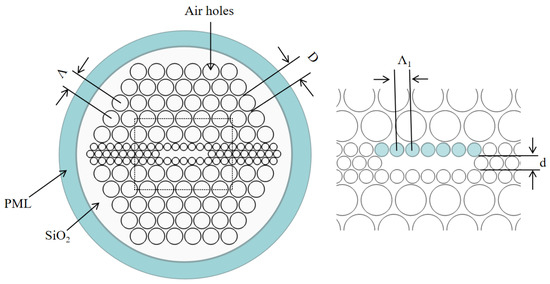
Figure 1.
Cross-sectional view of the proposed PCF.
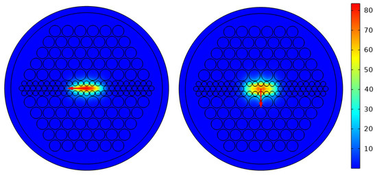
Figure 2.
The electric field distribution of the x- and y-polarized modes.
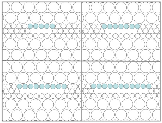
Figure 3.
Cross-sectional view of the proposed PCF in different m.
3.1. Birefringence
When the lattice constant = 1.4 m, the birefringence at different wavelengths is shown in Figure 4a. The confinement loss at a wavelength of 1.55 m and the birefringence curve at different lattice constants are shown in Figure 4b. For different m, the birefringence increases first and then decreases with the wavelength. When the length of the rectangular mode field increases and the width keeps stable, i.e., the ratio of length to width increases, the energy can be distributed more laterally. Thus, the asymmetry increases, leading to the increase in birefringence. The birefringence reaches 3.57 × 10 at 1.55 m and 3.57 × 10 over 1.55 m to 1.65 m. The birefringence can maintain the order of 3 × 10 over a wavelength range from 1.2 m to 2.0 m and above 2 × 10 over a wavelength range from 1.0 m to 2.0 m. As observed in Figure 4b, the decrease in lattice constant can increase the confinement loss. In order to obtain the maximum value of birefringence in the communication band of 1.55 m while maintaining a low confinement loss, m = 7 and lattice constant = 1.4 m are adopted as the optimal configuration in this paper.
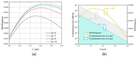
Figure 4.
Modal birefringence and confinement loss of the proposed PCF versus (a) and (b) .
3.2. Nonlinear Coefficient
Figure 5a,b exhibits the relation between nonlinear coefficient and wavelength for different m. With the optimal parameters N = 4, = 1.4 m, = 0.45, D = 0.9, and d = 0.4, high nonlinear coefficients of 41 W·km and 26 W·km for x- and y-polarizations can be achieved at a wavelength of 1.55 m while maintaining high birefringence. It can be seen from Figure 5 that the nonlinear coefficients decrease with the increase in m and decrease with the increase in wavelength. The former phenomenon is caused by the increase in the effective mode area of the rectangular mode field when m increases, while the latter phenomenon is related to the nonlinear coefficient calculation formula, which shows the nonlinear coefficient is inversely proportional to the area and wavelength of the effective mode field.
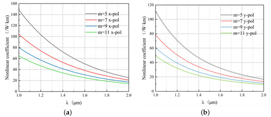
Figure 5.
Nonlinear coefficient of the proposed PCF versus : (a) x-polarization and (b) y-polarization.
3.3. Dispersion
Figure 6a,b, respectively, shows the dispersion curves of x- and y-polarization directions for different m and wavelengths. With the optimal parameters N = 4, = 1.4 m, = 0.45, D = 0.9, and d = 0.4, a flat dispersion interval is obtained in the x-polarization direction ranging from 1.3 m to 1.9 m. It has the potential to be used as the dispersion-compensating fiber element in high-speed and long-distance transmission system. Additionally, the dispersion performance of the PCF may make contributions to the generation of supercontinuum.
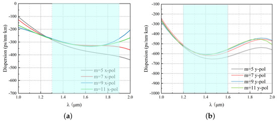
Figure 6.
Dispersion of the proposed PCF versus : (a) x-polarization and (b) y-polarization.
3.4. Confinement Loss
In Figure 7a,b, the confinement loss curves of x- and y-polarization directions for different m wavelengths are presented. The confinement losses for x- and y-polarization directions can be as low as 8.4 × 10 dB/m and 4.4 × 10 dB/m, respectively, at a wavelength of 1.55 m when N = 4, = 1.4 m, D = 0.9, = 0.45, and d = 0.4. It can be seen from the figure that the confinement loss increases with the increase in m and wavelength. The reason is that the length of the rectangular fiber core increases m, while the width remains the same, which elongates the mode field laterally and increases the area of the fiber core. The boundary condition is not fit to well confine the mode field in the core area. Moreover, there is a distance between small circular holes. When the transverse number of small circular holes, m, increases, the number of distances between holes also increases, which leads to a decrease in the light-limiting ability of small circular holes and an increase in leakage.
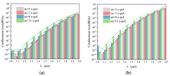
Figure 7.
Confinement loss of the proposed PCF versus : (a) x-polarization and (b) y-polarization.
3.5. Exploring Model Limits
The number of m is the main factor affecting all performance. In this part, we further analyze the impact of m on PCF performance as m varies from 3 to 23. The nonlinear coefficient, birefringence, and confinement loss curves with different m are shown in Figure 8a,b when N = 4, = 1.4 m, D = 0.9, = 0.45, d = 0.2, and = 1.55 m. Birefringence increases rapidly and then become stable with the increase in m. When the rectangle length-to-width ratio is below 9, the energy in the x-polarization direction is mainly limited by the air holes along the x-axis. The mode field of the x-pol mode is enlarged as m increase, and thus, the birefringence can be enhanced. However, when the ratio is above 9, the extending speed of the mode field of the x-pol mode becomes slow and finally close to zero. That means most of the energy is confined in a certain area of the fiber core, rather than spreading out endlessly. So, the birefringence becomes stable. As the spreading of the mode field is becoming slow, the nonlinear coefficients of the two polarizations decrease fast and then become relatively stable with the increase in m. The confinement loss decreases first and then increases as m increases. When m < 7, the length and area of the rectangular core increases with m, resulting in the matching between core area and mode field distribution; thus, the loss decreases. When m > 7, the core area keeps increasing and the confinement ability of the mode field degenerates, leading to an increase in confinement loss.
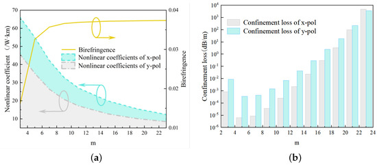
Figure 8.
Nonlinear coefficient, birefringence, and confinement loss of the proposed PCF versus m.
The width of the rectangular shape also affects various properties of the PCF. Figure 9 shows the electric field distribution at m = 5 and m = 11. In this study, the above and below parts of the structure, excluding the small circular holes in the central row, are moved upward and downward by a distance h to investigate the effects of different rectangular widths on fiber properties. As shown in Figure 10, when h is negative, meaning that the air holes are closer to the fiber core, the decrease in the gap increases the local air-filling ratio. Although the decrease in the width of the rectangular mode field increases asymmetry, the stronger compression of the fiber core leads to energy escaping and an increase in loss, while the birefringence decreases. On the other hand, when h increases, the gap increases, resulting in a decrease in loss and a decrease in birefringence. As seen in Figure 10b, there is only a slight variation in the mode field area and nonlinear coefficient, which further indicates the strong stability of the structure proposed in this paper.

Figure 9.
The electric field distribution of the x- and y-polarized modes at m = 5 (a,b) and m = 11 (c,d).
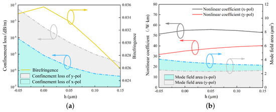
Figure 10.
Modal birefringence and confinement loss (a); nonlinear coefficient and mode field area (b) of the proposed PCF versus h.
The diameter of the small circle undoubtedly affects the performance of the fiber; when keeping other parameters constant, the position of the large air hole in the cladding limits the size of the inner small circle. Increasing the diameter of the small circle reduces the gap between the small circles and between the small circle and the large circle, which increases birefringence and reduces loss, but also weakens the mechanical strength during processing. Therefore, this paper analyzes the performance changes within a ±5% range of the small circle diameter variation shown as Table 1. In the manufacturing process, the position and diameter of the small circle may cause changes in fiber performance due to the failure to reach the standard size. Regarding the influence of the small circle position on performance, as analyzed earlier, the effect of the small circle diameter within the +5% range on various properties is further analyzed as an indication of the error tolerance of this structure. Increasing the small circle diameter further compresses the rectangular mode field, which increases its asymmetry and also reduces the gap between the circles, which is the fundamental reason for subsequent performance changes. When the central small circle hole diameter fluctuates within +5%, the birefringence change is within +1% and the nonlinear coefficient change is within +0.1%; when the central small circle hole diameter fluctuates within −5%, the birefringence change is within −2%, and the nonlinear coefficient change is within −3%. Although the limiting loss increases, it is still within an acceptable range. Therefore, this structure is proven to have good error tolerance in manufacturing.

Table 1.
The influence of the diameter on each performance.
3.6. Manufacturing Feasibility
The development level of fiber preparation technology directly affects the progress of our practical fiber design. Generally, the construction of preform is a key step in the preparation of optical fibers. The diameters are usually on the order of centimeters. The cross-sections’ arrangement of the preform determines the final geometry structure of the desired optical fiber. According to the different construction methods of fiber preform, the common preparation processes of photonic crystal fiber include the stacking and drawing method [37,38], mechanical drilling method [39], die extrusion method [40], internal casting method [12], etc. In addition, there is a recently developed 3D printing fiber preform method. As the process has improved, more readily available round capillary glass tubes have been used to replace regular hexagonal ones. The gaps between the structures can be eliminated simply through air pressure control during the drawing process.
The process of producing a photonic crystal fiber preform using the capillary stacking method involves pulling thin glass tubes and thin rods for stacking, arranging them in a designed structure, and then bundling them together before placing them inside a quartz tube to form the preform rod. Due to the fact that fused silica is a typically viscous and incompressible fluid, during the process of drawing a photonic crystal fiber, the preform rod located in the heating zone of the graphite furnace is heated to a molten and softened state and continuously pulled by a traction device to form the fiber.
When the ratio of d/ increases, the proportion of light in the fiber increases. This is because the mutual compression force between the air holes is stronger, which makes it easier to maintain the prearranged structure of the drawn fiber, and the reduced gap between the air holes makes the energy less likely to escape, resulting in reduced losses. However, this sacrifices mechanical strength. Existing research has shown that larger air-filling ratios are achievable [41,42,43,44], and various two-sized circular designs have been proven feasible [45,46,47]. Several structures that are structurally similar to the proposed PCF have been successfully fabricated [48,49,50]. In summary, the production process of the PCF in this article can refer to many experiences, and the PCF can be made through the stacking and drawing process with a high probability. Photonic crystal fibers have a large number of structural simulation designs and different properties. However, due to the limitation of the current manufacturing and processing level, most of the complex designs of photonic crystal fibers can hardly be realized at present. In this paper, an all-circular air hole design is designed and only two diameters of circular holes are used, which reduces the difficulty of manufacturing and increases the feasibility while maintaining excellent performance.
Table 2 is supplemented with some highly birefringent PCFs with ellipses or rectangular fiber core, classifying them based on the core shape. It can also be seen from the table that rectangular fiber cores generally have larger confinement loss, and elliptical fiber cores have a higher nonlinear coefficient. These characteristics are in accordance with the above description and explanation of these two types of fiber cores. While maintaining excellent birefringence, the proposed PCF avoids the common loss problem of rectangular fiber cores [12] and greatly improves the nonlinear coefficient, which can be better than a lot of elliptical fiber cores [18].
Table 2.
Comparison between the Properties of Proposed PCF and Other PCFs.
4. Conclusions
In this study, we presented the design of a rectangular fiber core photonic crystal fiber (PCF) where a single row of large circular holes at the center is replaced by three rows of smaller circular holes. The fiber core is constructed using the missing air hole in the center. The full-vector finite element method, combined with the perfect matching layer’s absorption boundary conditions, was employed to perform a comprehensive analysis and numerical optimization of the structure. This includes examining the modal field distribution, birefringence, nonlinear coefficient, and dispersion characteristics of the designed PCF. When the optimal parameters are finalized, namely = 1.4 m, = 0.45, D = 0.9, d = 0.4, and m = 7, the birefringence can reach 3.57 × 10 at a wavelength of 1.55 m. Furthermore, the confinement losses of the x- and y-polarization directions are 4.4 × 10 dB/m and 8.4 × 10 dB/m, respectively. The nonlinear coefficients are up to 41 W·km and 26 W·km. The flat dispersion interval can be obtained at a wavelength ranging from 1.3 m to 1.9 m. The proposed PCF can maintain a birefringence of 10 orders of magnitude in a wide-spectrum range from 1 m to 2 m. The special structure in this paper only employs two sizes of circular holes and avoids complex designs. With these characteristics, the proposed PCF has high potential to be used for fiber communication, dispersion compensation and preparation of polarization-maintaining fiber, polarization-controllable precision optical fiber sensors, and supercontinuum generation.
Author Contributions
Conceptualization, Z.L.; methodology, Z.L.; software, J.W.; validation, Z.L., T.Y. and Z.Z.; formal analysis, Z.L.; investigation, Z.L.; resources, Z.L.; data curation, Z.L.; writing—original draft preparation, Z.L.; writing—review and editing, Z.L. and T.Y.; visualization, Z.L.; supervision, T.Y.; project administration, T.Y. and Y.D.; funding acquisition, T.Y. and Y.D. All authors have read and agreed to the published version of the manuscript.
Funding
This work was supported in part by the National Natural Science Foundation of China under Grant 62205364, in part by the China Postdoctoral Science Foundation under Grant 2022M713291, in part by the Shenzhen Research Foundation under Grant JSGG20201103091401005, in part by the Shenzhen Research Foundation under Grant JCYJ20220818101206015, and in part by the Shenzhen Research Foundation under Grant JSGG20220831103402004.
Institutional Review Board Statement
Not applicable.
Informed Consent Statement
Not applicable.
Data Availability Statement
Not applicable.
Conflicts of Interest
The authors declare no conflict of interest.
References
- Knight, J.; Birks, T.; Russell, P.S.J.; Atkin, D. All-silica single-mode optical fiber with photonic crystal cladding. Opt. Lett. 1996, 21, 1547–1549. [Google Scholar] [CrossRef] [PubMed]
- Paul, B.K.; Ahmed, K.; Asaduzzaman, S.; Islam, M.S. Folded cladding porous shaped photonic crystal fiber with high sensitivity in optical sensing applications: Design and analysis. Sens. Bio-Sens. Res. 2017, 12, 36–42. [Google Scholar] [CrossRef]
- Mortensen, N.A.; Nielsen, M.D.; Folkenberg, J.R.; Jakobsen, C.; Simonsen, H.R. Photonic crystal fiber with a hybrid honeycomb cladding. Opt. Express 2004, 12, 468–472. [Google Scholar] [CrossRef] [PubMed]
- Ahmed, K.; Morshed, M. Design and numerical analysis of microstructured-core octagonal photonic crystal fiber for sensing applications. Sens. Bio-Sens. Res. 2016, 7, 1–6. [Google Scholar] [CrossRef]
- Agrawal, A.; Kejalakshmy, N.; Rahman, B.A.; Grattan, K.T. Soft glass equiangular spiral photonic crystal fiber for supercontinuum generation. IEEE Photonics Technol. Lett. 2009, 21, 1722–1724. [Google Scholar] [CrossRef]
- Bala, A.; Chowdhury, K.R.; Mia, M.B.; Faisal, M. Highly birefringent, highly negative dispersion compensating photonic crystal fiber. Appl. Opt. 2017, 56, 7256–7261. [Google Scholar] [CrossRef]
- Liang, S.; Yang, Y.; Kang, S.; Zhang, Y.; Sheng, X.; Lou, S.; Wang, X.; Zhang, W.; Zhao, T. Influences of asymmetrical geometric structures on the birefringence of index-guiding photonic crystal fiber. Optik 2019, 180, 973–983. [Google Scholar] [CrossRef]
- Sharma, M.; Dixit, V.; Konar, S.; Ahmed, K.; Dhasarathan, V. Endlessly single-mode photonic crystal fiber with high birefringence for sensing applications. Mod. Phys. Lett. B 2020, 34, 2050077. [Google Scholar] [CrossRef]
- Mondal, K. A comparative study of birefringence in photonic crystal fiber employing various lattice geometries with all-circular air holes. Optik 2020, 215, 164699. [Google Scholar] [CrossRef]
- Yang, T.; Zhang, L.; Shi, Y.; Liu, S.; Dong, Y. A highly birefringent photonic crystal fiber for terahertz spectroscopic chemical sensing. Sensors 2021, 21, 1799. [Google Scholar] [CrossRef] [PubMed]
- Saha, R.; Hossain, M.M.; Rahaman, M.E.; Mondal, H.S. Design and analysis of high birefringence and nonlinearity with small confinement loss photonic crystal fiber. Front. Optoelectron. 2019, 12, 165–173. [Google Scholar] [CrossRef]
- Faisal, M.; Bala, A.; Roy Chowdhury, K.; Mia, M.B. Highly birefringent large negative dispersion-flattened photonic crystal fibre for broadband residual dispersion compensation. J. Mod. Opt. 2018, 65, 1577–1583. [Google Scholar] [CrossRef]
- Mia, M.M.A.; Islam, M.A.; Miah, M.S.; Bhowmik, B.; Mahir, S.M.; Biswas, S.K. Highly Birefringent Dispersion Compensating Index Guiding Square Photonic Crystal Fiber with Large Nonlinearity for Fiber Optic Transmission System. In Proceedings of the 2020 International Conference on Computer, Electrical & Communication Engineering (ICCECE), Kolkata, India, 17–18 January 2020; IEEE: Piscataway, NJ, USA, 2020; pp. 1–5. [Google Scholar]
- Hossain, S.; Shah, S.; Faisal, M. Ultra-high birefringent, highly nonlinear Ge20Sb15Se65 chalcogenide glass photonic crystal fiber with zero dispersion wavelength for mid-infrared applications. Optik 2021, 225, 165753. [Google Scholar] [CrossRef]
- Alishacelestin, X.; Raja, A.S.; Muthu, K.E.; Selvendran, S. A novel ultra-high birefringent photonic crystal fiber for nonlinear applications. Braz. J. Phys. 2021, 51, 605–617. [Google Scholar] [CrossRef]
- Choyon, A.S.J.; Chowdhury, R. Multifunctional chalcogenide (As2S3, As2Se3) dual-core photonic crystal fiber with elliptical air-hole for mid-IR optical communications: Design and analysis. Optik 2022, 258, 168857. [Google Scholar] [CrossRef]
- Yang, T.-Y.; Jiang, H.-M.; Wang, E.-L.; Xie, K. Photonic crystal fibers with large birefringence and high nonlinearity in near-infrared band. J. Infrared Millim. Waves 2015, 35, 350–354. [Google Scholar]
- Dadkhahfard, S.; Mirsalehi, M.M. Highly birefringent photonic crystal fiber with flattened negative dispersion over the S+ C+ L+ U wavelength bands. In Proceedings of the 2017 Iranian Conference on Electrical Engineering (ICEE), Tehran, Iran, 2–4 May 2017; IEEE: Piscataway, NJ, USA, 2017; pp. 1655–1659. [Google Scholar]
- Liu, Q.; Ren, Z.; Liu, W.; Sun, Y.; Lv, T.; Liu, C.; Lu, W.; Li, B.; Jiang, Y.; Sun, T.; et al. A photonic quasi-crystal fiber composed of circular air holes with high birefringence and low confinement loss. Optik 2021, 231, 166497. [Google Scholar] [CrossRef]
- Alishacelestin, X.; Raja, A.S.; Selvendran, S. A highly birefringent photonic crystal fiber with compact cladding layers suitable for fiber optic gyroscope application. Laser Phys. 2021, 31, 065101. [Google Scholar] [CrossRef]
- Naeem, K.; Chung, Y.; Kim, B.H. Sagnac interferometer based on a highly-birefringent two-core PCF: Theory, experiment, and sensing characteristics. J. Light. Technol. 2020, 38, 5177–5190. [Google Scholar] [CrossRef]
- Hu, D.J.J.; Ho, H.P. Recent advances in plasmonic photonic crystal fibers: Design, fabrication and applications. Adv. Opt. Photonics 2017, 9, 257–314. [Google Scholar] [CrossRef]
- Kim, B.; Kim, T.H.; Cui, L.; Chung, Y. Twin core photonic crystal fiber for in-line Mach-Zehnder interferometric sensing applications. Opt. Express 2009, 17, 15502–15507. [Google Scholar] [CrossRef]
- Chen, H.; Wei, H.; Liu, T.; Zhou, X.; Yan, P.; Chen, Z.; Chen, S.; Li, J.; Hou, J.; Lu, Q. All-fiber-integrated high-power supercontinuum sources based on multi-core photonic crystal fibers. IEEE J. Sel. Top. Quantum Electron. 2014, 20, 64–71. [Google Scholar] [CrossRef]
- Katsuyama, T.; Matsumura, H.; Suganuma, T. Propagation characteristics of single polarization fibers. Appl. Opt. 1983, 22, 1748–1753. [Google Scholar] [CrossRef]
- Noda, J.; Okamoto, K.; Sasaki, Y. Polarization-maintaining fibers and their applications. J. Light. Technol. 1986, 4, 1071–1089. [Google Scholar] [CrossRef]
- Varnham, M.; Payne, D.; Birch, R.; Tarbox, E. Single-polarisation operation of highly birefringent bow-tie optical fibres. Electron. Lett. 1989, 25, S42–S44. [Google Scholar] [CrossRef]
- Ghanbari, A.; Olyaee, S. Highly Nonlinear Composite-Photonic Crystal Fibers with Simplified Manufacturing Process and Efficient Mid-IR Applications. Crystals 2023, 13, 226. [Google Scholar] [CrossRef]
- Jones, D.J.; Diddams, S.A.; Ranka, J.K.; Stentz, A.; Windeler, R.S.; Hall, J.L.; Cundiff, S.T. Carrier-envelope phase control of femtosecond mode-locked lasers and direct optical frequency synthesis. Science 2000, 288, 635–639. [Google Scholar] [CrossRef] [PubMed]
- Holzwarth, R.; Udem, T.; Hänsch, T.W.; Knight, J.; Wadsworth, W.; Russell, P.S.J. Optical frequency synthesizer for precision spectroscopy. Phys. Rev. Lett. 2000, 85, 2264. [Google Scholar] [CrossRef] [PubMed]
- Udem, T.; Holzwarth, R.; Hänsch, T.W. Optical frequency metrology. Nature 2002, 416, 233–237. [Google Scholar] [CrossRef] [PubMed]
- Wang, Y.; Zhao, Y.; Nelson, J.; Chen, Z.; Windeler, R.S. Ultrahigh-resolution optical coherence tomography by broadband continuum generation from a photonic crystal fiber. Opt. Lett. 2003, 28, 182–184. [Google Scholar] [CrossRef]
- Humbert, G.; Wadsworth, W.; Leon-Saval, S.; Knight, J.; Birks, T.; Russell, P.S.J.; Lederer, M.; Kopf, D.; Wiesauer, K.; Breuer, E.; et al. Supercontinuum generation system for optical coherence tomography based on tapered photonic crystal fibre. Opt. Express 2006, 14, 1596–1603. [Google Scholar] [CrossRef] [PubMed]
- Hartl, I.; Li, X.; Chudoba, C.; Ghanta, R.; Ko, T.; Fujimoto, J.; Ranka, J.; Windeler, R. Ultrahigh-resolution optical coherence tomography using continuum generation in an air–silica microstructure optical fiber. Opt. Lett. 2001, 26, 608–610. [Google Scholar] [CrossRef] [PubMed]
- Loh, W.; Laming, R.I.; Robinson, N.; Cavaciuti, A.; Vaninetti, F.; Anderson, C.; Zervas, M.; Cole, M. Dispersion compensation over distances in excess of 500 km for 10-Gb/s systems using chirped fiber gratings. IEEE Photonics Technol. Lett. 1996, 8, 944–946. [Google Scholar] [CrossRef]
- Gruner-Nielsen, L.; Wandel, M.; Kristensen, P.; Jorgensen, C.; Jorgensen, L.V.; Edvold, B.; Pálsdóttir, B.; Jakobsen, D. Dispersion-compensating fibers. J. Light. Technol. 2005, 23, 3566–3579. [Google Scholar] [CrossRef]
- Russell, P. Photonic crystal fibers. Science 2003, 299, 358–362. [Google Scholar] [CrossRef] [PubMed]
- Buczynski, R. Photonic crystal fibers. Acta Phys. Pol. A 2004, 106, 141–167. [Google Scholar] [CrossRef]
- Mori, A. 1.5 μm band zero-dispersion shifted tellurite photonic crystal fibre with a nonlinear coefficient γ of 675 W−1·km−1. ECOC2004 Stockh. 2004, 10025088940. [Google Scholar]
- Selleri, S.; Vincetti, L.; Cucinotta, A.; Zoboli, M. Complex FEM modal solver of optical waveguides with PML boundary conditions. Opt. Quantum Electron. 2001, 33, 359–371. [Google Scholar] [CrossRef]
- Kristensen, J.T.; Houmann, A.; Liu, X.; Turchinovich, D. Low-loss polarization-maintaining fusion splicing of single-mode fibers and hollow-core photonic crystal fibers, relevant for monolithic fiber laser pulse compression. Opt. Express 2008, 16, 9986–9995. [Google Scholar] [CrossRef]
- Benabid, F. Hollow-core photonic bandgap fibre: New light guidance for new science and technology. Philos. Trans. R. Soc. A Math. Phys. Eng. Sci. 2006, 364, 3439–3462. [Google Scholar] [CrossRef]
- Wadsworth, W.; Witkowska, A.; Leon-Saval, S.; Birks, T. Hole inflation and tapering of stock photonic crystal fibres. Opt. Express 2005, 13, 6541–6549. [Google Scholar] [CrossRef] [PubMed]
- Chaudhuri, P.R.; Roy, S. Determining properties of fabricated index-guiding photonic crystal fibers using SEM micrograph and mode convergence algorithm. J. Light. Technol. 2008, 26, 379–386. [Google Scholar] [CrossRef]
- Xiao, L.; Demokan, M.; Jin, W.; Wang, Y.; Zhao, C.L. Fusion splicing photonic crystal fibers and conventional single-mode fibers: Microhole collapse effect. J. Light. Technol. 2007, 25, 3563–3574. [Google Scholar] [CrossRef]
- Holdynski, Z.; Napierala, M.; Jozwik, M.; Szostkiwicz, L.; Mergo, P.; Nasilowski, T. Three fold symmetric microstructured fibers for customized sub-nanosecond supercontinuum generation. Opt. Commun. 2017, 393, 45–48. [Google Scholar] [CrossRef]
- Cho, T.Y.; Kim, G.H.; Lee, K.I.; Lee, S.B.; Jeong, J.M. Study on the fabrication process of polarization maintaining photonic crystal fibers and their optical properties. J. Opt. Soc. Korea 2008, 12, 19–24. [Google Scholar] [CrossRef]
- Martynkien, T.; Statkiewicz-Barabach, G.; Olszewski, J.; Wojcik, J.; Mergo, P.; Geernaert, T.; Sonnenfeld, C.; Anuszkiewicz, A.; Szczurowski, M.K.; Tarnowski, K.; et al. Highly birefringent microstructured fibers with enhanced sensitivity to hydrostatic pressure. Opt. Express 2010, 18, 15113–15121. [Google Scholar] [CrossRef]
- Geernaert, T.; Kalli, K.; Koutsides, C.; Komodromos, M.; Nasilowski, T.; Urbanczyk, W.; Wojcik, J.; Berghmans, F.; Thienpont, H. Point-by-point fiber Bragg grating inscription in free-standing step-index and photonic crystal fibers using near-IR femtosecond laser. Opt. Lett. 2010, 35, 1647–1649. [Google Scholar] [CrossRef]
- Martynkien, T.; Szpulak, M.; Statkiewicz, G.; Golojuch, G.; Olszewski, J.; Urbanczyk, W.; Wojcik, J.; Mergo, P.; Makara, M.; Nasilowski, T.; et al. Measurements of sensitivity to hydrostatic pressure and temperature in highly birefringent photonic crystal fibers. Opt. Quantum Electron. 2007, 39, 481–489. [Google Scholar] [CrossRef]
- Prabu, K.; Malavika, R. Highly birefringent photonic crystal fiber with hybrid cladding. Opt. Fiber Technol. 2019, 47, 21–26. [Google Scholar] [CrossRef]
- Hasan, M.R.; Islam, M.A.; Rifat, A.A.; Hasan, M.I. A single-mode highly birefringent dispersion-compensating photonic crystal fiber using hybrid cladding. J. Mod. Opt. 2017, 64, 218–225. [Google Scholar] [CrossRef]
- Halder, A.; Anower, M.S. Relative dispersion slope matched highly birefringent and highly nonlinear dispersion compensating hybrid photonic crystal fiber. Photonics Nanostruct.-Fundam. Appl. 2019, 35, 100704. [Google Scholar] [CrossRef]
- Yu, B.; Rui, H. A simple design of highly birefringent and nonlinear photonic crystal fiber with ultra-flattened dispersion. Opt. Quantum Electron. 2019, 51, 1–13. [Google Scholar] [CrossRef]
- Wang, E.; Cheng, P.; Zhao, W.; Li, J.; Han, Q.; Zhou, X. Photonic crystal fibers with high birefringence and multiple zero dispersion wavelengths. Opt. Fiber Technol. 2020, 58, 102309. [Google Scholar] [CrossRef]
- Hossain, M.M.; Ahsan, M.S.; Sikder, N.; Rahaman, M.E.; Al-Mamun Bulbul, A.; Mondal, H.S. High birefringence and broadband dispersion compensation photonic crystal fiber. J. Opt. Commun. 2021, 000010151520200140. [Google Scholar] [CrossRef]


Disclaimer/Publisher’s Note: The statements, opinions and data contained in all publications are solely those of the individual author(s) and contributor(s) and not of MDPI and/or the editor(s). MDPI and/or the editor(s) disclaim responsibility for any injury to people or property resulting from any ideas, methods, instructions or products referred to in the content. |
© 2023 by the authors. Licensee MDPI, Basel, Switzerland. This article is an open access article distributed under the terms and conditions of the Creative Commons Attribution (CC BY) license (https://creativecommons.org/licenses/by/4.0/).