1. Introduction
A supercontinuum (SC) refers to a laser source with a broad spectrum and has been widely studied [
1,
2,
3]. Typically, an SC is generated in fibers by non-linear effects, with the SC spectra relying on the pump wavelength, pulse width, pump power, and non-linear fiber. Many applications require a flat SC, which can be achieved through a suitable non-linear fiber [
4,
5]. However, the pump laser cannot be entirely converted into other wavelengths through non-linear frequency conversion, leading to a residual pump pulse that can be detrimental to the application of the SC. High residual pump pulses can cause damage to experimental devices and materials, particularly to human biological tissues, which limits the application of the SC in the biological field. Moreover, detectors with dynamic response ranges linked to laser intensity are often used for SC applications. Consequently, a detector with a high-power remaining pump will not respond to signals with weak intensities at other wavelengths. Therefore, reducing the remaining pump pulse of the SC is necessary.
To apply an SC, it is necessary to either select a specific band or reduce the intensity at the pump wavelength of the SC to protect the detection device. There are few research reports that focus on reducing a specific band compared with high-pass and low-pass filters. However, the demand for such research is not low; most research reports on band-stop filters have been circuit-based, and a limited number of research reports on SC shaping have utilized anti-resonant fibers. In SC-based LiDAR, several filter sets are used to select different bands [
6]. Researchers have previously applied a hot mirror to cut off surplus bands from the SC when using it for confocal interference–reflection microscopy [
7]. Interferometric filters, gratings, acousto-optic tunable filters, and other devices can be used to select the wavelength band, but these spatial structure methods are generally limited to a narrow wavelength range or require additional controllers. By contrast, the all-fiber structure has numerous advantages, including simplicity, convenience, small size, lightweight, easy maintenance, and good stability [
8,
9,
10]. Long-period fiber gratings have unique advantages in wide transmission bands, low back reflection, and an all-fiber structure [
8,
9,
10]. They are also useful in spectral shaping. However, the dispersion or nonlinearity of long-period fiber gratings may affect the pulse, which can cause a change in spectral shape. For spectral shaping, hollow-core anti-resonant fibers (HCARFs) are particularly useful. HCARFs have been shown to have a wide and tunable transmission band; low dispersion, as demonstrated in the study by Liu et al. (2009); and nonlinearity, providing superior spectral filtering capabilities in comparison with other methods [
11]. The all-fiber structure of HCARFs greatly improves the stability compared with the above-mentioned methods. Moreover, HCARFs can be applied in the mid-infrared band and can withstand higher power because the light is transmitted along the air core. Thus, utilizing HCARF reasonably can effectively mitigate some of the issues mentioned above.
HCARF was first theoretically demonstrated in 1995 [
12], and since then, it has attracted considerable attention from researchers [
13,
14,
15,
16,
17,
18]. Researchers are committed to reducing the loss of HCARF [
19,
20,
21]. Wu et al. investigated the effect of cladding materials on the loss of HCARF in 2019 and 2020 [
22,
23]. In addition, HCARFs exhibit excellent transmission performance in the mid-infrared band [
24]. Yu et al. described a silica HCARF for mid-infrared transmission with a minimum attenuation of 34 dB/km at a wavelength of 3050 nm in 2012 [
25]. Other studies based on anti-resonant fibers have also been reported. Sollapur investigated SC generation in a gas-filled HCARF in 2017 [
26]. Among various shapes of HCARFs, the fourfold semi-tube structure, as reported in [
27], has been found to exhibit high birefringence and low confinement loss. The recent study [
28] also introduced a 5-tube HCARF with ultralow loss and single-mode operation. The combined use of HCARFs and spectral shaping techniques through all-fiber structures has led to significant progress in SC performance and efficiency. In particular, the usage of hollow-core photonic bandgap fiber (HC-PBGF) proposed in [
29] has been useful in creating low confinement loss sensors for gases such as acetylene. By leveraging the properties of HC-CAPBG fibers, such as low attenuation, single-mode operation, and low bending sensitivity, the realization of low confinement loss sensing for trace gases can be achieved. Additionally, HCARFs can be spliced with other fibers [
30], which means all-fiber equipment using HCARFs can be achieved.
In this study, we proposed using HCARFs as a broadband filter to generate a flat SC. We found suitable parameters using simulation and manufactured effective HCARFs according to these parameters. Finally, the manufactured HCARF successfully reduced the intensity of the SC at the pump wavelength of 1064 nm in the experiment, achieving the objective of shaping the SC.
2. Methods
Resonance matching between the fiber and the pump wavelength is crucial for shaping an SC with HCARFs as a broadband filter. HCARFs have a unique spectral response due to their anti-resonance characteristic, which can be manipulated and optimized by adjusting their structure [
31]. However, achieving resonance between the pump wavelength and the anti-resonant wavelength is essential for effective filtering of the residual pump pulse and shaping the spectrum of SC. This resonance-matching is determined by the fiber’s structural parameters, such as the thickness of the capillary wall and the diameter of the hollow core. The proposed design used PCFs, which have a broader bandwidth and a higher nonlinear coefficient compared with standard single-mode fibers due to their unique periodic structure of tiny holes that create photonic bandgaps, increasing the effective mode area and reducing dispersion. [
32]. The anti-resonance mechanism of HCARFs suppresses the propagation of light in the cladding, making it possible for the fiber to guide light in the hollow core with low loss. HCARFs have been demonstrated to effectively guide light and control its spectral properties in various studies [
33]. The unique spectral response and transmission performance of HCARFs make them an excellent candidate for reducing the intensity of the residual pump pulse and shaping the SC into a flat spectrum.
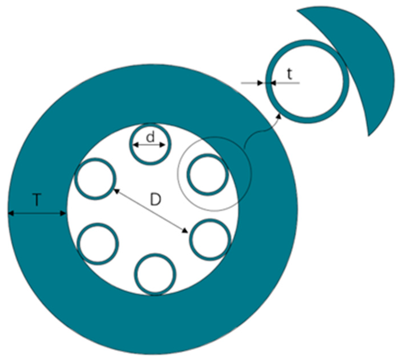
An HCARF consists of a hollow core region surrounded by one or multiple capillaries, forming a structure that guides light in the core, as illustrated in
Figure 1. D denotes the core diameter, d represents the inner diameter of the tube, and t is the thickness of the tube. The mechanism of HCARF guidance has been discussed in previous studies.
The loss of an HCARF is related to the wavelength of light. The principle of HCARFs can be explained by the principle of anti-resonance reflection in an optical waveguide (ARROW) [
34]. When light is coupled into the core and transmitted to the interface between the core and the cladding, light waves that match the resonance conditions will be coupled into the capillary and radiate out, and other light waves that do not match the resonance conditions will be reflected into the core area and continue to propagate in the core. The anti-resonance condition of the optical fiber is related to the t of the capillary. The relationship between the resonance wavelength and t is defined as [
35]:
where
is the m-order resonant wavelength, and
n1 and
n2 are the refractive indices of the core and the capillary, respectively. The resonant wavelength corresponds to the center wavelength of the high-loss region, and there is a low-loss transmission band in the adjacent anti-resonant wavelength.
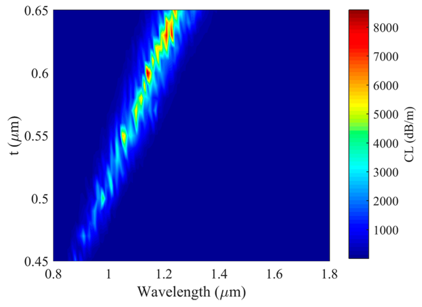
Before the experiment, we used commercial software to calculate the loss in the wavelength range of 0.8–1.8 μm with a variable t. The core diameter D was set to 20 μm and the tube’s inner diameter d was set to 5 μm. Note that the cladding-to-core diameter ratio (d/D) mainly affects the loss value, and hence, when considering only the material loss, there exists an optimal value for d/D [
23]. However, in this manuscript, we primarily focused on the thickness parameter t, given that it has a stronger impact on the transmission spectrum. Therefore, we did not explicitly discuss the influence of d/D on the transmission spectrum of the fiber and set it as a constant value throughout our simulations.
The confinement loss (CL) of the HCARF calculated for different values of t is shown in
Figure 2. The CL at the resonant wavelength was much higher than that at all other wavelengths.
We hoped to obtain an HCARF with a resonance wavelength of 1064 nm. As shown in
Figure 2, at a wavelength of 1064 nm, when the t of the HCARF was 0.553 μm, the effect was the best, and it can be seen that the loss between 0.54 and 0.56 was considerable. Although the accuracy requirement for t seems to be very high, with the increasingly mature manufacturing technology of optical fiber, the loss of anti-resonant optical fiber has been reduced to close to the theoretical limit in many studies. As shown in
Figure 2, even a slight error in t can lead to a significant loss in the 1064 nm band, thus achieving the goal of SC shaping.
As shown in
Figure 3a, there was a peak loss of more than 2000 dB/m at a wavelength of 1064 nm, and there was a second peak at 1100 nm with a loss of approximately 800 dB/m. We also analyzed the effective refraction index neff of the HCARF, and the results are shown in
Figure 3b. neff decreased with increasing wavelength for the low-loss bands, but there was a step in the range of the resonant band, which was caused by the mode field change of the resonant band.
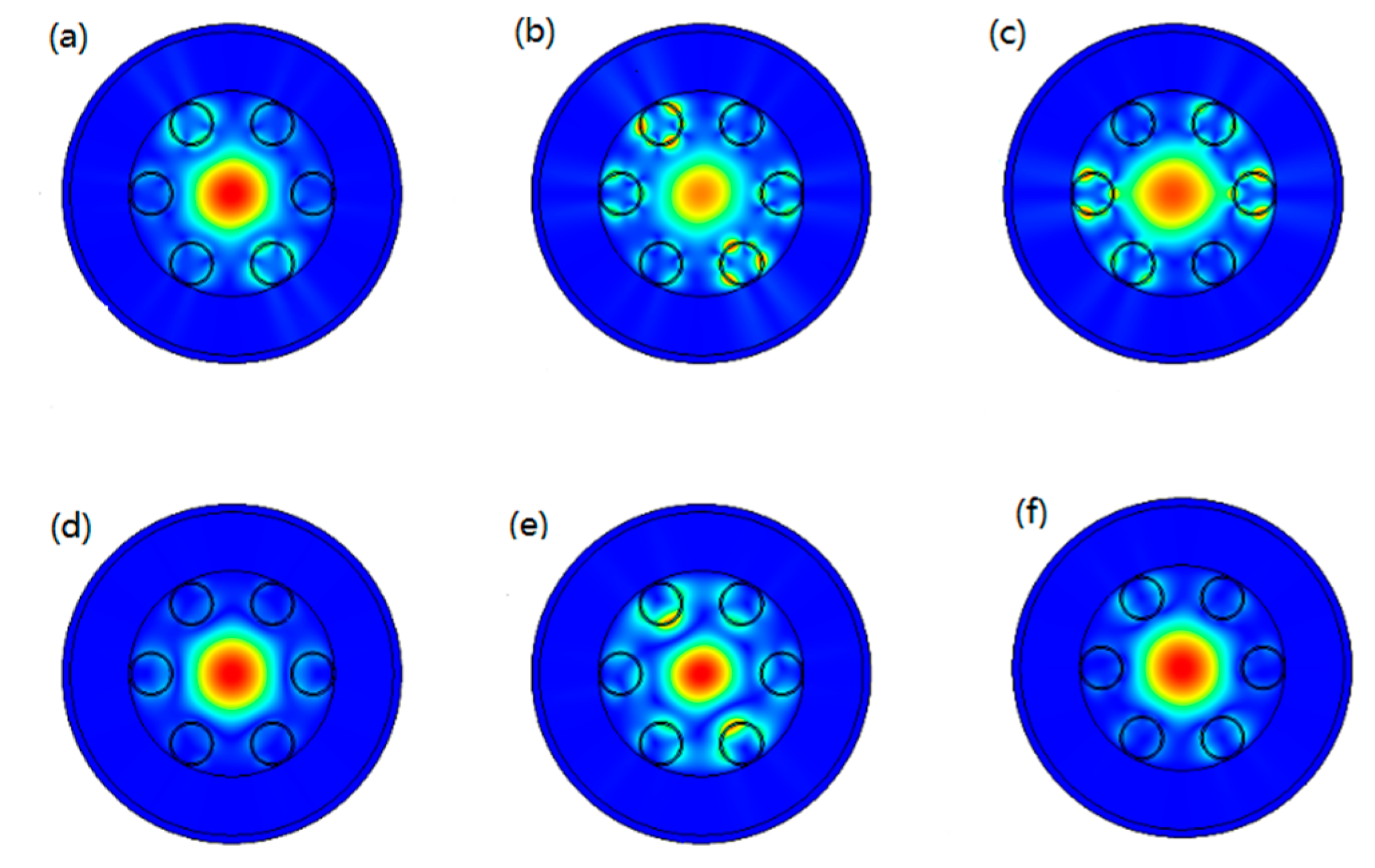
Loss and neff are related to the optical modes of the HCARF. To study the secondary peak at 1100 nm, we simulated the fundamental mode field distribution of different wavelengths in the anti-resonant fiber; the results are shown in
Figure 4. The optical modes were not completely confined to the core around the resonant wavelength, and high loss was caused by these leaked modes.
Figure 4e shows the primary cause of the secondary peak at 1100 nm.
3. Materials
In the last section, the loss spectrum of anti-resonant fiber was simulated by the finite element method with the ultimate goal of obtaining a suitable fiber structure for the spectrum shaping of the SC.
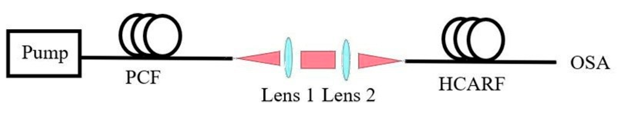
Figure 5 illustrates the experimental setup in which an SC was generated in a photonic crystal fiber (PCF) from a pump pulse laser, and surplus pump light was due to incomplete nonlinear conversion. From the SC spectrum, there was a strong peak at the pump wavelength. The anti-resonant fiber was used to reduce the intensity of this peak. The SC from the PCF passed through a telescope system consisting of a pair of lenses coupled with an HCARF. A telescope system was used because the light spot emitted from the PCF was small, with a mode field diameter of about 5 μm. However, the core size of the anti-resonant fibe is on the order of tens of microns, making a telescope system appropriate.
The experimental conditions were as follows: the PCF had a core diameter of 4.8 μm, the focal length of lens 1 was 5 mm, lens 2’s focal length was 20 mm, the core diameter of the anti-resonant fiber was 20 μm, and t was about 1 μm.
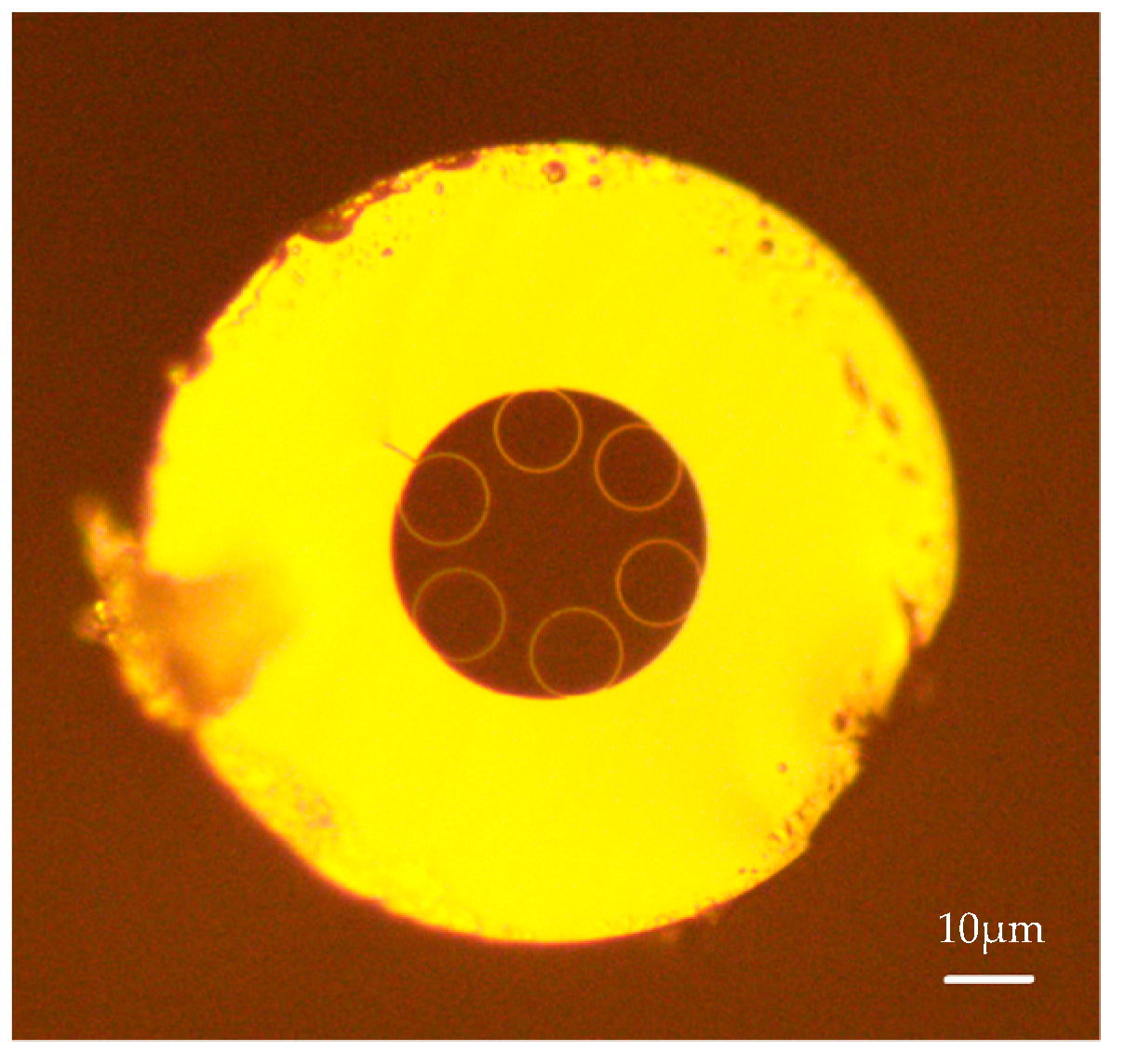
Figure 6 shows the cross-section of the HCARF used in the experiment.
According to the resonant wavelength formula, a certain t can correspond to multiple resonant wavelengths. Considering a pump wavelength of around 1 um, the fundamental resonant wavelength of a fiber with a t of around 0.55 μm corresponds to the pump wavelength, while the second-order resonant wavelength of a fiber with a t of around 1 μm corresponds to the pump wavelength. In the simulation, we mainly considered the fundamental resonant wavelength of the fiber, which is why a parameter of 0.553 μm was used. However, during the fabrication of the fiber, it was difficult to make the tube wall this thin, and we also lacked equipment with sub-nanometer precision. The second-order resonant wavelength of a fiber with a t of around 1 μm corresponds to the pump wavelength, so we made a fiber with a t of around 1 μm.
4. Results and Discussion
The results of this paper consist of two parts: simulation and experiment.
According to the ARROW theory, when the thickness t is 0.553 μm, high loss occurs at wavelengths of around 530 nm and shorter, other than the resonant wavelength of 1060 nm. Similarly, when the thickness is around 1 μm, the resonant wavelength becomes 2120 μm, and the second-order resonance wavelength is 1060 μm; other high-loss wavelengths are present at wavelengths of around 530 nm and shorter. The supercontinuum intensity at these wavelengths has been observed to be very low, rendering the impact on the results negligible.
4.1. Simulation
Figure 7a illustrates that the spectrum of the SC generated by the PCF fell in the 0.8–1.8 μm range. Except for a strong peak at 1064 nm, the spectra of other bands are relatively flat. The peak at 1064 nm was about 17 dB higher than that of other wavelength bands, which was mainly due to incomplete nonlinear conversion and more surplus pump light. To reduce the intensity of light around 1064 nm, we conducted simulations using a 5 mm long HCARF with the same parameters as those mentioned earlier in the paper, where D was 20 μm, d was 5 μm, and t was 0.553 μm. As shown in
Figure 7b, the intensity at 1064 nm decreased by about 17 dB, while the intensity of other bands of the SC did not change much. Before shaping the spectrum, the intensity of the SC in the range of 0.8–1.8 μm was extremely low, with the strongest component of the spectrum differing by 37 dB from the weakest component. After the spectrum shaping, the difference in spectral intensity in that frequency band has been reduced to 19 dB.
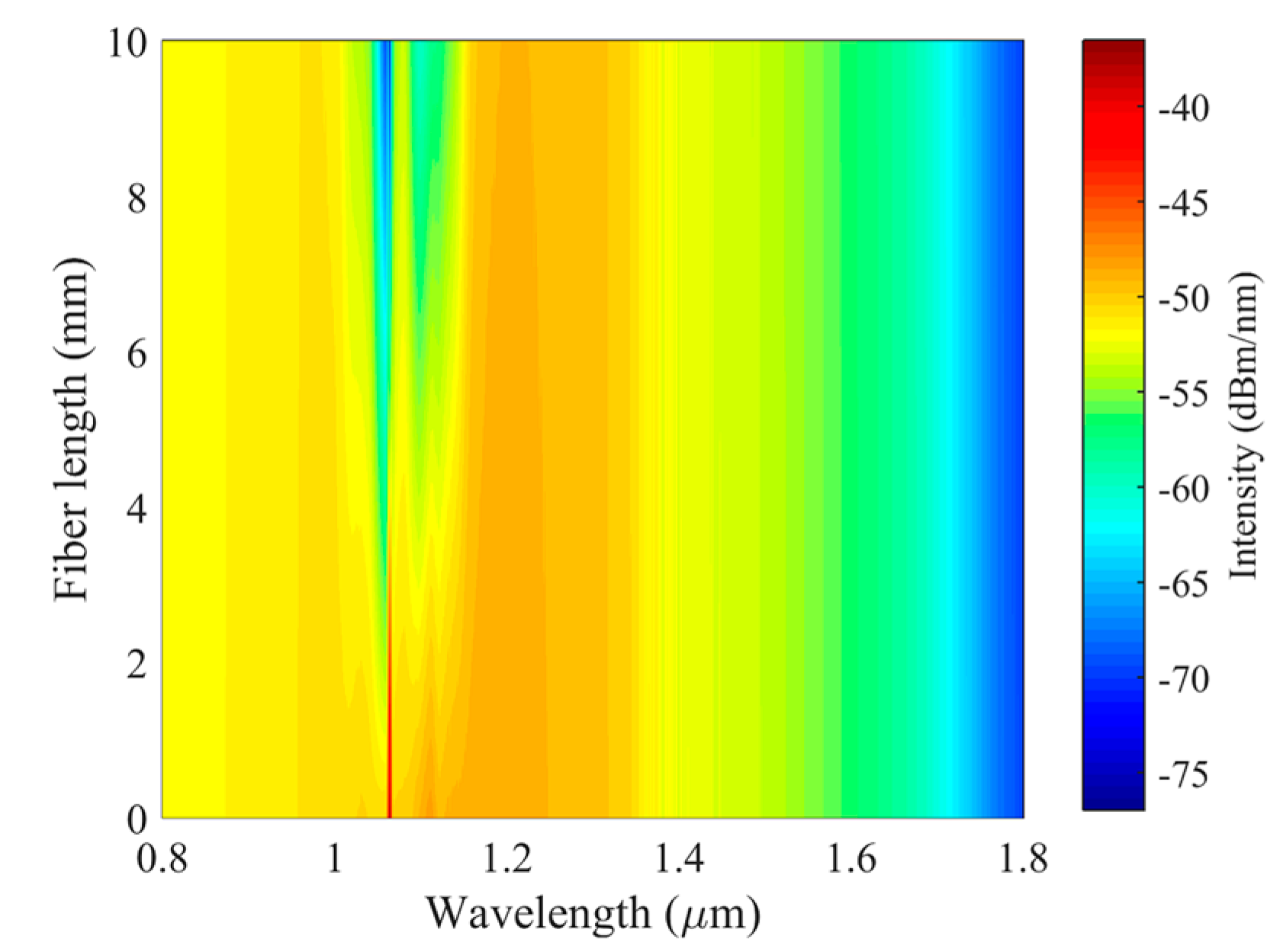
When shaping an SC using anti-resonant fiber, the structural parameters of the anti-resonant fiber must match the SC’s spectral shape. The length of the fiber utilized also impacts the shaping effect.
Figure 8 shows the spectral shaping results of the SC mentioned above at different lengths of anti-resonant fibers. It can be seen in the figure that when the anti-resonant fiber used was less than 2 mm, the intensity at the pump wavelength in the original SC was still very large, and the effect of spectrum shaping was not good. When the length of the anti-resonant fiber used exceeded 8 mm, the intensity at the pump wavelength of the SC spectrum was far lower than the surrounding intensity, which meant that the light in this wavelength band near the pump wavelength was almost completely consumed and could not be used later. Therefore, it is very important to choose an appropriate fiber length. According to the calculation results, when the length of the anti-resonant fiber is about 5 mm, the best spectral shaping effect can be achieved.
4.2. Experiment
On the basis of the previous simulation results, we conducted experimental research on the spectral shaping of the SC.
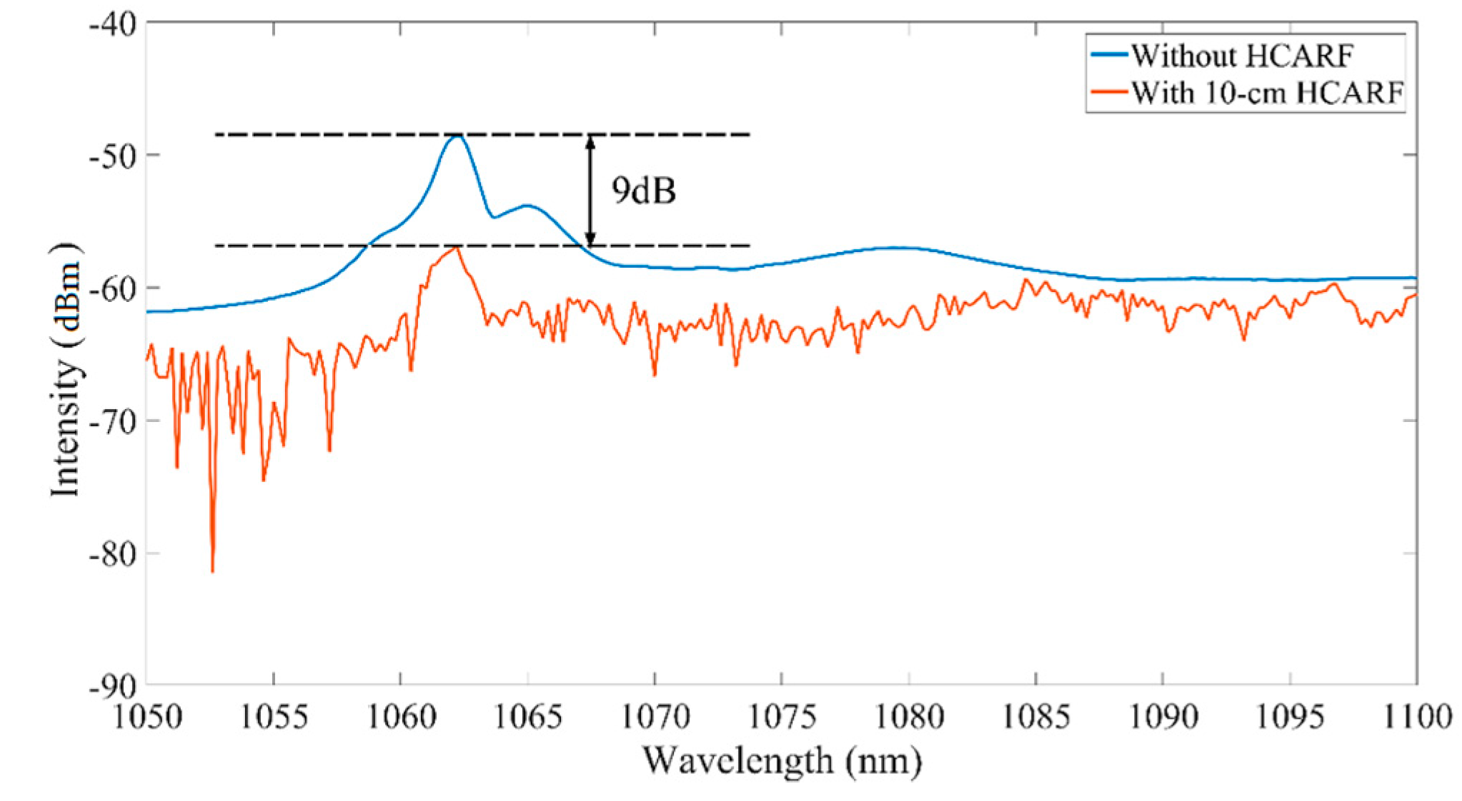
In the last section, we introduced the experimental equipment and specific conditions. With the same parameters, after numerous attempts, we achieved excellent outcomes using a 10 cm HCARF. The experimental results are presented in
Figure 9. We used a 10 cm HCARF to reduce the intensity of the pump wavelength of the SC by approximately 9 dB.
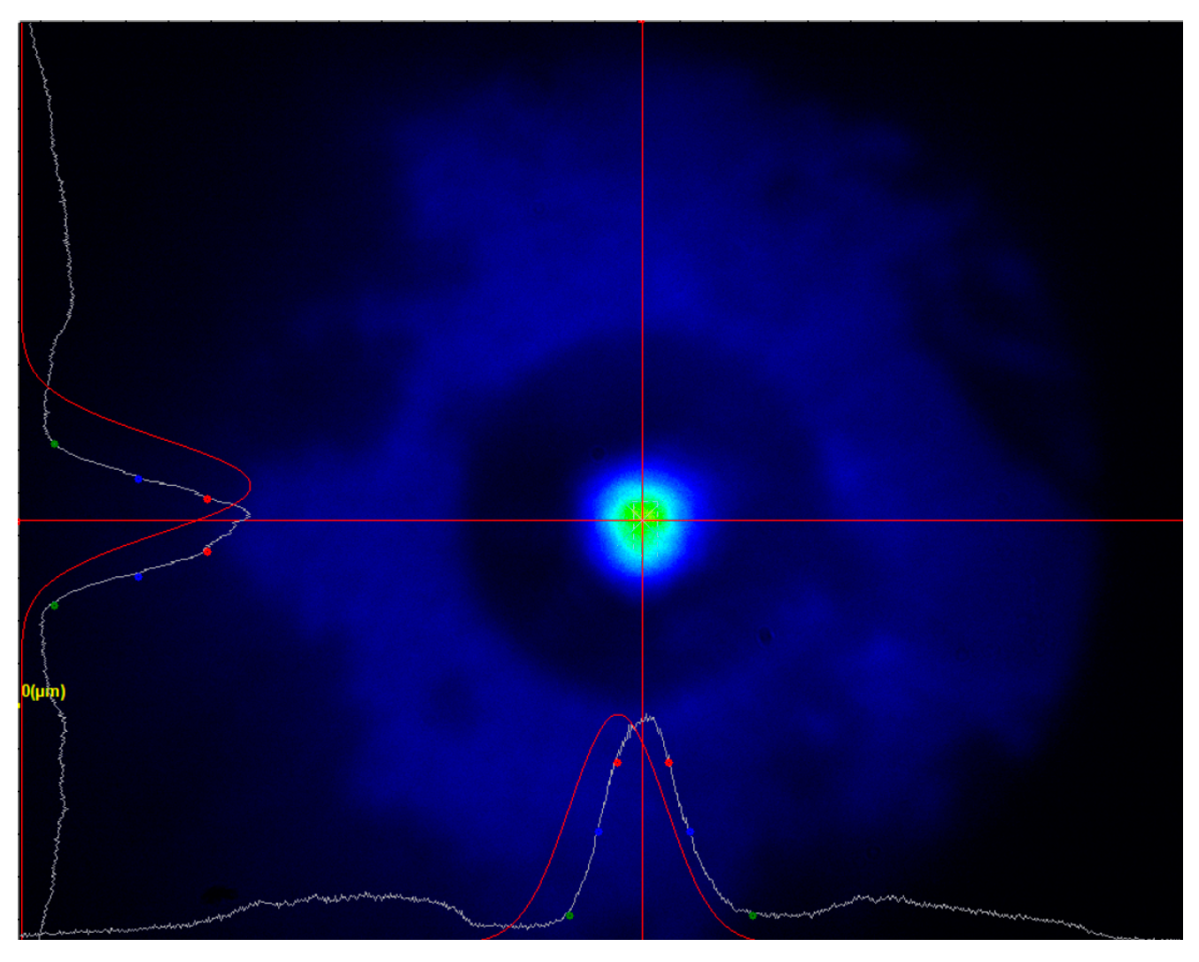
Comparing the experimental results with the simulation research, it was found that the length of the anti-resonant fiber used in the experiment was longer than the expected length of the fiber. This may be due to the fact that when two lenses are used for beam expansion coupling, the incident light does not completely enter the core of the anti-resonant fiber, and there may be some modes transmitted in the tube, as shown in
Figure 10, which reduces the mode selection ability of the anti-resonant fiber.
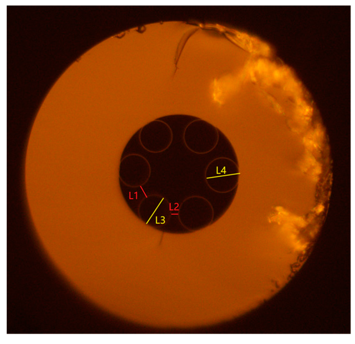
The transmission bandwidth of the anti-resonant fiber used in the experiment was also narrower than expected, and there were some minor fluctuations in the spectrum. This may have been due to the uneven distribution of air pressure in each capillary during the drawing process of the anti-resonant fiber, and the precise control of the drawing speed was not achieved. The cross-sectional view in
Figure 11, depicting the rear part of the optical fiber in
Figure 6, shows an uneven structure that contrasts the uniform six quartz tubes presented in
Figure 6. Four vertical lines labeled L1 (5.33 μm), L2 (2.88 μm), L3 (12.907 μm), and L4 (13.968 μm) were added to
Figure 11 to indicate the respective lengths of the uneven HCARF structure in millimeters.
Although t is difficult to measure because of its small value, it is not difficult to infer that process problems may make the t of several capillary walls of the fiber possibly inconsistent, and t may also change along the length of the fiber. As the resonance wavelength is sensitive to the influence of t, the transmission bandwidth became smaller, resulting in a decrease of the fiber t. In addition, the non-uniformity of the optical fiber leads to an increase in the loss band and a decrease in the peak value of the loss, which may be another reason why the length of the optical fiber used was longer than expected. In view of this situation, it is necessary to improve the manufacturing process in future optical fiber manufacturing processes and process higher quality anti-resonant optical fibers for experiments.
Low-loss fusion splicing between PCFs and HCARFs presents a slight challenge owing to the hollow core. HCARFs in particular are more prone to reaching their softening point. However, with a reasonably set overlap, fusion time, and fusion current, low-loss fusion splicing is achievable [
36]. Therefore, an all-fiber structure can be realized

 ,
, 