Article

High Efficient Random Laser with Cavity Based on the Erbium-Doped Germanophosphosilicate Artificial Rayleigh Fiber

1
Kotelnikov Institute of Radioengineering and Electronics (Fryazino Branch), Russian Academy of Sciences, Vvedensky Sq. 1, 141190 Fryazino, Moscow Region, Russia
2
Dianov Fiber Optics Research Center, Prokhorov General Physics Institute, Russian Academy of Sciences, St. Vavilova 38, 119333 Moscow, Russia
3
Kotelnikov Institute of Radioengineering and Electronics, Russian Academy of Sciences, St. Mokhovaya 11-7, 125009 Moscow, Russia
4
G. G. Devyatykh Institute of Chemistry of High-Purity Substances, Russian Academy of Sciences, St. Tropinina 49, 603951 Nizhny Novgorod, Russia
*
Author to whom correspondence should be addressed.
Photonics 2023, 10(7), 748; https://doi.org/10.3390/photonics10070748
Submission received: 31 May 2023 / Revised: 26 June 2023 / Accepted: 26 June 2023 / Published: 28 June 2023
(This article belongs to the Special Issue Fiber Laser and Their Applications)

Abstract

:
The Erbium “random” laser, based on the artificial Rayleigh fiber, has been comparatively studied in detail under two different pump conditions: 974.5 and 1485 nm pumping wavelengths. The artificial Rayleigh 7-m-long fiber was used as a laser cavity, it was formed by the ultraviolet (UV) inscription of the uniform array of the weakly reflective fiber Bragg grating (FBG) during the fiber drawing process. The UV photosensitivity of the Erbium-doped fiber originated from the specially developed (germanophosphosilicate) core glass composition. The emission spectrum of the fabricated “random” fiber laser had a single narrow peak at the 1548 nm wavelength. It was clearly revealed that the extension of the laser cavity by the separate wavelength-matched 90%-reflective FBG resulted in a significant laser efficiency growth. The highest laser slope efficiency of 33% and the laser output power of 80 mW were reached in the FBG-modified cavity at the 974.5-nm-wavelength pumping. The continuous-wave operation mode of this laser has been confirmed. The laser linewidth value measured by the delayed self-heterodyne technique was about 550 Hz.

1. Introduction

Optical fibers (OF) are currently used for telecommunications, sensor systems and lasers. Currently, a new direction that is known as “random” fiber lasers [1,2,3,4] is actively developing. This direction of photonics has become a subject of great interest for researchers around the world due to the fact that random fiber lasers are able to generate light with unique performance characteristics without imposing strict requirements on the optical cavity. In this case, amplification is achieved due to the Raman scattering effects [2] or stimulated Brillouin scattering (SBS) [3]. The feedback in optical fibers is achieved due to the weak stationary (“frozen into the glass grid”) scattering centers, uniformly distributed over a fiber length (Rayleigh scattering). This leads to the fact that the cavity of random lasers is constructed using long (1–100 km) OFs. The current trends in “random” fiber lasers are associated with the transition to lasers with cavities, based on an array of the weakly reflective, identical fiber Bragg gratings (FBGs) [5,6]. FBG arrays are also called “artificial Rayleigh fibers”, as they are mainly used to increase the intensity of the return optical signal and reduce the cavity length because the reflection signal from Rayleigh scattering is extremely small [4] (−82 dB for pulses with duration of 1 ns). For random laser development, it is important to explore and fabricate the artificial Rayleigh fibers with optimal characteristics.
The process of forming such structures by UV radiation is carried out in several iterations: first, a polymer coating is removed from the OF section with a length of ~10 mm, then an FBG is formed in it using laser UV radiation, after which the OF section with the inscribed FBG is overcoated by polymer, and the whole procedure is repeated in the next section of the OF. The usage of the described technique contributes to a significant increase in the return signal, but also causes a deterioration in the mechanical strength of the optical fiber in the places where the FBG is inscribed. This significantly narrows the possibilities and scope of the FBG arrays. Moreover, the number of FBGs in such an array is limited. This disadvantage is devoid of the method of femtosecond inscribing by laser radiation in the visible, or IR, range. In this case, the removal of the coating is not required, which is noted in [7,8]. However, both methods for manufacturing large FBG arrays require significant, often unjustified data, labor costs.
The solution to the problem was the development of special OFs with extended FBG arrays, which are inscribed directly during the process of extracting the OF with UV radiation [9,10,11,12,13,14,15]. FBGs are inscribed in such an optical fiber using pulsed radiation from an excimer UV laser and a phase mask. The number of FBGs per 100 m of such an OF can reach 10,000 pieces. In other words, such OFs can be totally inscribed by FBGs. The increase in the return signal, compared to the Rayleigh scattering level (contrast), reaches values of 50 dB at the Bragg wavelength of 1550 nm. The typical width of the reflection spectrum of the 100%-filling FBG array that is inscribed during the drawing process is 0.3 nm. Using a chirped phase mask to write an FBG array, it is possible to obtain a total reflectance spectrum width of an array of 4 nm. This is necessary for the application of FBG arrays in coherent reflectometry systems operating in wide temperature ranges [15,16]. However, in this case, the level of the reflected signal may decrease.
As compared with the Rayleigh backscattering in optical fibers, backscattering in an OF with an FBG array is characterized by a fairly narrow width of the reflection spectrum, which is determined by the width of the reflection spectrum of individual FBGs. However, within the reflection line itself, the reflection spectra of the OFs with an FBG array are similar to the Rayleigh scattering spectra. They are characterized by a random (Rayleigh) distribution of the amplitude reflection coefficient over the frequency and represent an alternation of maxima and minima on a typical scale, determined by the inverse time of light travel along the entire length of a fiber. Thus, provided that the operating frequency range is within the reflection spectrum of the gratings, OFs with an FBG array are a good alternative to traditional Rayleigh fibers and, therefore, called “artificial Rayleigh fibers”. In particular, they can be effectively used in such applications as coherent reflectometry [15,16] and random lasers [17,18,19,20,21,22,23,24,25,26].
The spectrum of the reflection of each FBG in array depends on the ambient temperature, tension and refraction coefficient (which is non-permanent in preform and can change a little bit in the OF drawing process). Such factors form a non-phase array with a typical width of 0.2–0.3 nm in opposition to the narrow-width phase grating using in DFB lasers.
Weakly reflective FBG arrays can be also inscribed in active OFs doped with rare-earth ions (erbium, ytterbium and bismuth). It makes it possible to create OFs that combine both an increased reflectivity and the possibility of forming dynamic gratings, which are important for the spectral selection of laser radiation [19,20,27,28]. Such OFs are a good fit for making the cavities for compact random lasers.
The main advantage of random lasers with a cavity, based on an array of FBGs, is the narrow band emission with continuous-wave operation at relatively small cavity lengths (less than 10 m). However, previously such lasers’ configurations have shown a relatively low efficiency of the laser’s radiation (less than 10%) [20,21,26].
This article is the evolution of our previous works, including an optimization of random laser cavities, based on artificial Rayleigh fibers, and adapted to the conventional telecom wavelength range (also known as “C-band” range). The main novelty is the development of an artificial Rayleigh fiber on the basis of a special photosensitive Er-doped OFs with a germanophosphosilicate core matrix.

2. Materials and Methods

The experimental setup developed “in-house” [26] was implemented to fabricate FBG arrays during the fiber drawing process. The source of UV radiation was an Optosystems CL-5100 pulsed KrF excimer laser [29] with the 248 nm illumination wavelength and a pulse duration of 10 ns. Each of the FBGs in the array was inscribed with a pulse fluence of 400 mJ/cm2.
In this work, we used a phase mask, manufactured by Ibsen Photonics with a working area of 10 × 10 mm and a period of 1070 nm. The OF drawing rate is about 10 m/min. The single FBG inscription in the array was performed in one pulse. The phase mask was installed in the immediate vicinity of the fiber being drawn. The typical length of a single FBG was 10 mm long, which has been determined by the width of the laser beam and the working length of the phase mask. The duty cycle of the FBG along the length of the fiber (inscribing density) was controlled by synchronizing the drawing speed and the repetition rate of the UV laser pulses. Thus, with a pulse repetition rate of 10 Hz and an extraction speed of 6 m/min, a fully filled (100%) array with separated FBGs has been achieved. It should be noted that a halving of the laser’s pulse repetition frequency (to 5 Hz) at the constant drawing speed indicates the 50% filling of FBG array. In this case, the distance between the individual FBGs is equal to their length, i.e., equal to 10 mm.
In this work, the artificial Rayleigh fiber samples were fabricated from the preform with an erbium-doped core. This preform was synthesized, utilizing the original MCVD method of the separate component deposition, which has been already described in detail in our previous work [26]. The core material was germanophosphosilicate glass doped by the erbium oxide as the activator (Er2O3-GeO2-P2O5-SiO2). According to the results of studying the elemental composition of the core glass using an X-ray analyzer (JEOL 5910LV), the average value of the P2O5 concentration was 12 mol.% and GeO2 was 1.5 mol.%. The erbium concentration turned out to be below the detection limit of the analyzer (less than 0.1 at .%). The preform was stretched and jacketed to the first mode cutoff wavelength of 0.94 μm. The difference between the refractive indices of the core and cladding in the jacketed preform, measured using a Photon Kinetics P2610 preform analyzer, was 0.015.
We used the method of optical frequency domain reflectometry (OFDR) [30] with a Luna 4400 device to characterize the fabricated FBG arrays. In addition, we used a Yokogawa AQ6370D optical spectrum analyzer (OSA) with a maximum optical resolution of 0.02 nm for the spectral measurements of the FBG array reflection. Additionally, this OSA was used for the measurements of the OF absorption spectra. The source of radiation for the spectral measurements was a superluminescent diode with a fiber output (for the FBG array samples) or a halogen lamp (for the conventional OF samples).
The single-mode OF with a standard outer diameter of 125 µm was drawn from the preform. The fiber had a core diameter of 4.8 μm and cutoff wavelength of 900 nm.
The level of background (or “gray”) optical losses was about 2 dB/km, which is a sign of the homogeneous structure of the core glass and the absence of the transition metal impurities in it. The intensities of the Er3+ ion absorption peaks at 980, 1490 and 1535 nm in the fiber were 3.3, 3.1 and 7 dB/m, respectively. The transmission spectrum of the fiber in the extended telecommunications wavelength range (1460–1620 nm) measured with an optical resolution of 1 nm is shown in Figure 1.
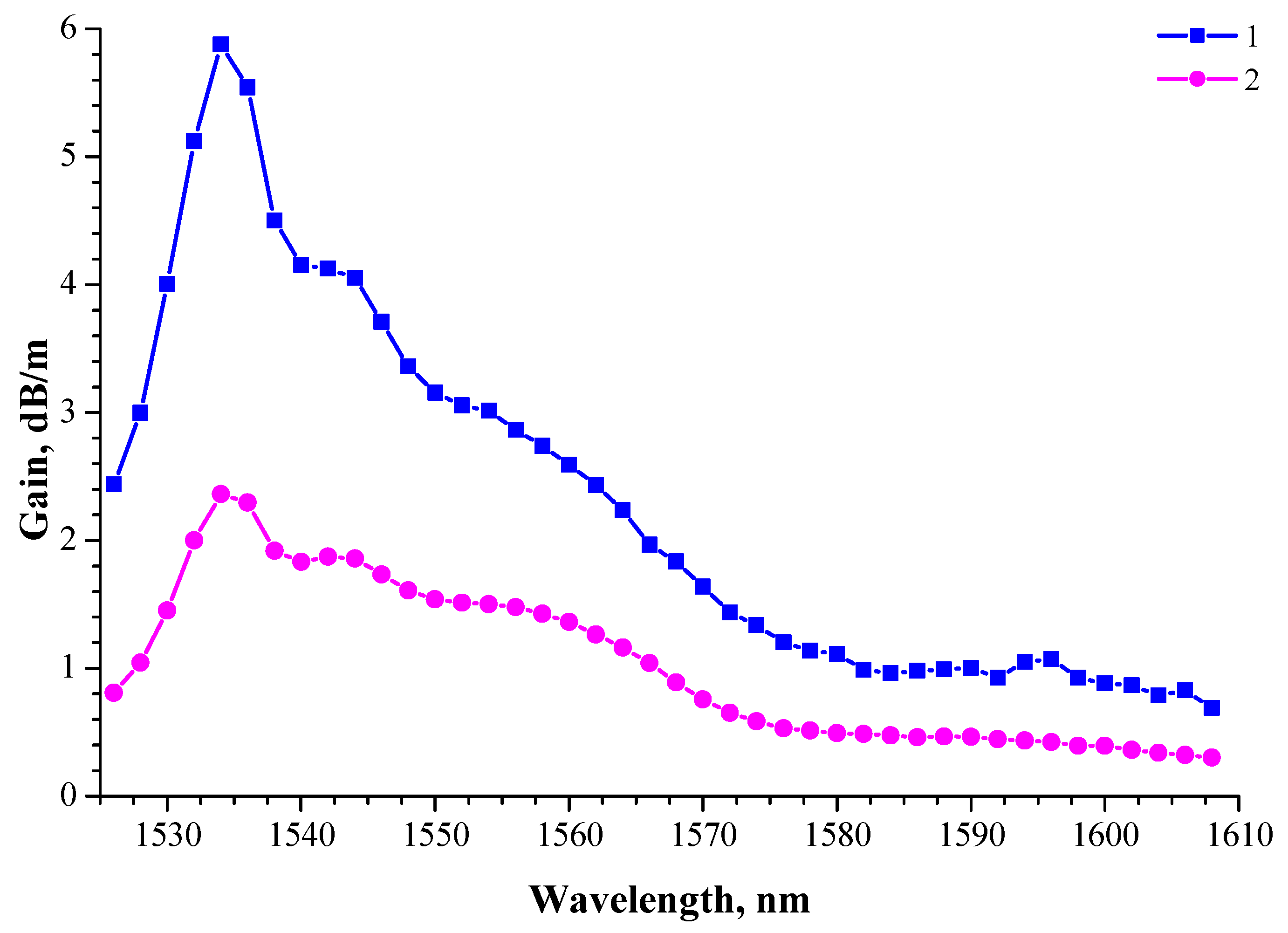
The small-signal gain of an active fiber is fundamentally important to find the optimal configuration of a fiber laser cavity and evaluate its generation characteristics. The small-signal gain in the fiber was measured in the wavelength range of 1525–1610 nm using two APEX AP1000-5 and AP1000-8 platforms equipped with AP3350A tunable semiconductor single-frequency lasers (operated in range of 1525–1610 nm) and AP3352A (operated in range of 1575–1610 nm). Both were used as weak signal sources. Two laser diodes radiated at a wavelength of 976 or 1485 nm were used as sources for the active fiber pumping. Using the technique described above, the spectral dependences of the gain in the telecommunications wavelength range (C- and L-range) were obtained for two pumping schemes: at a wavelength of 976 nm (Figure 2, curve “1”) and 1485 nm (Figure 2, curve “2”).
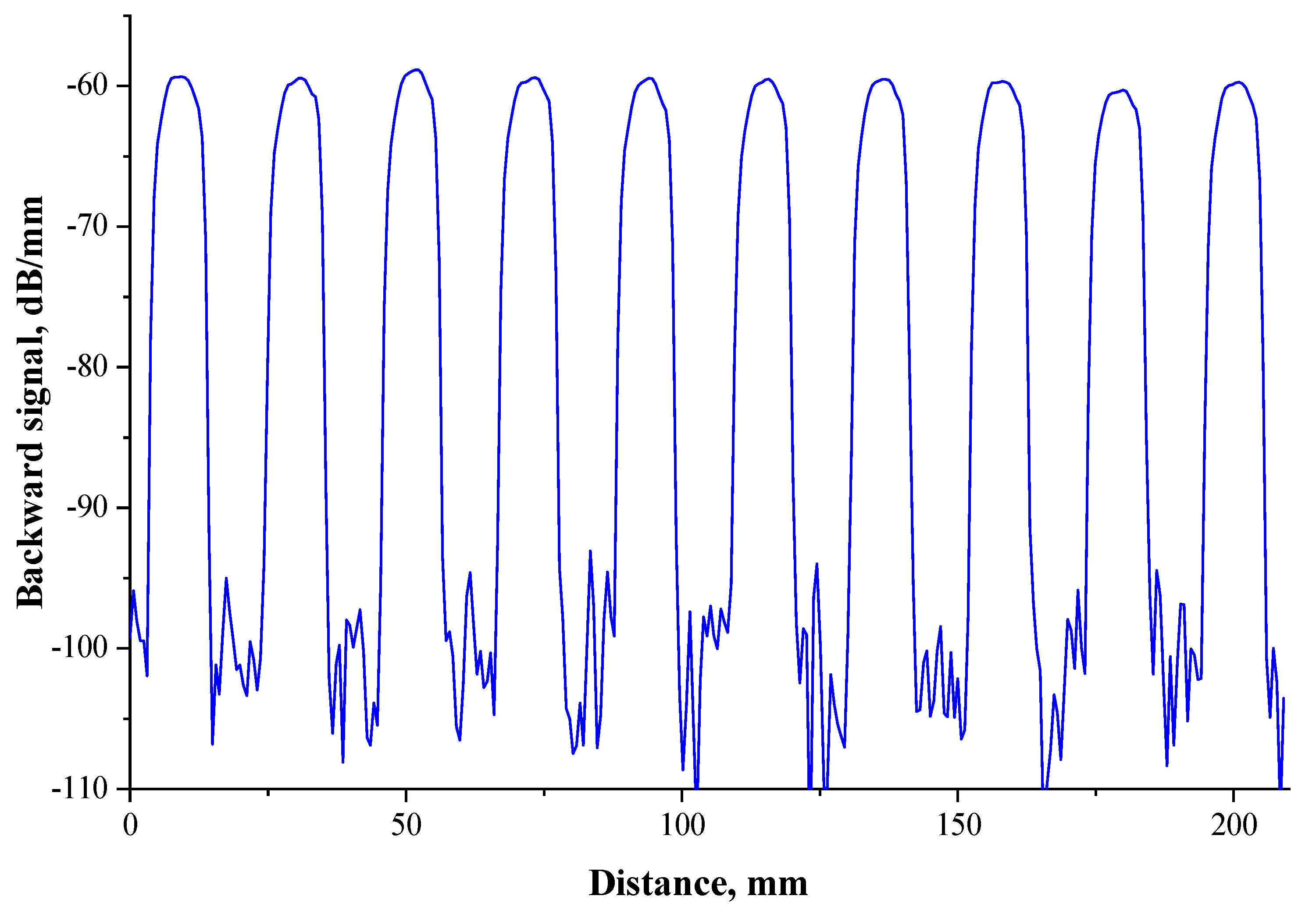
The main object of our research in this work was the artificial Rayleigh fiber: a 7-m-long array filled on the 100% uniformly by weakly reflective FBGs. Moreover, another similar fiber sample with a 50% FBG filling was fabricated for inscription contrast measurement (the excess of the return signal above the Rayleigh level). The FBG inscription contrast obtained by the OFDR technique was up to 45 dB (see Figure 3).
Figure 4 reveals the optical reflection spectrum of the 100%-filled 7-m-long weakly reflective FBG array, which has been obtained by OSA with an optical resolution of 0.1 nm. Next, this sample was used as the “random” laser cavity.
The basic scheme of the laser investigation experimental setup is depicted in Figure 5. The “random” laser cavity (1) was backward-pumped via a wavelength-division multiplexer (WDM) (2) by using one of the two laser diodes (3): Photonics 3S1999CHP (emission wavelength 974.5 nm) and Anritsu GF4B701 (emission wavelength 1485 nm). The optical power of the pumping radiation was controlled by a CNILaser LP100 powermeter. The laser output radiation passed through the optical isolator (4) to avoid the influence of back-reflection. The OSA Yokogawa AQ6370D (5) was used for the laser emission spectral measurements, and Grandway FHM2B01 or JDSU MP-60 powermeters (6) were used for the laser optical power measurements. Optionally, the highly reflective FBG (7) was used to extend the “random” laser cavity and its lasing properties have also been studied. In addition to the basic measurements, the laser operation mode has been investigated by Extech MS6060 oscilloscope and the special self-heterodyne radio-frequency (RF) setup.

3. Results

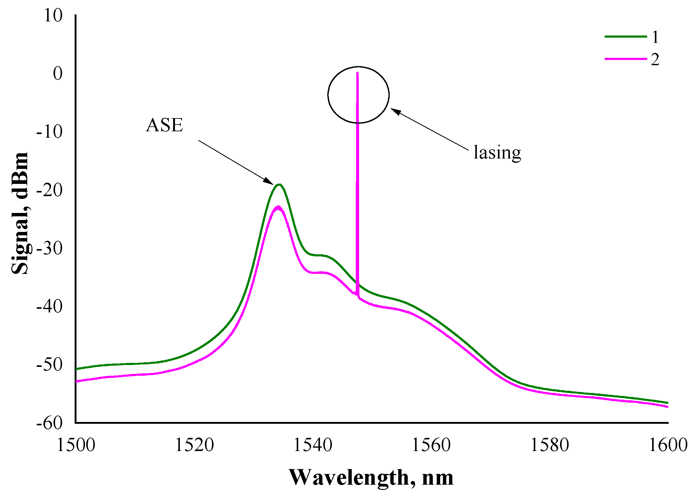
The cavity of the “random” laser studied in this work generated narrow-band radiation at a wavelength of 1548 nm. As can be seen from Figure 6, the “telecom wavelength-range” spectrum of the pumped 7-m-long artificial Rayleigh fiber has a single narrow peak, while only the erbium amplified luminescence (ASE) is visible in the spectrum of the same conventional (i.e., without weakly reflective FBGs) pumped fiber.
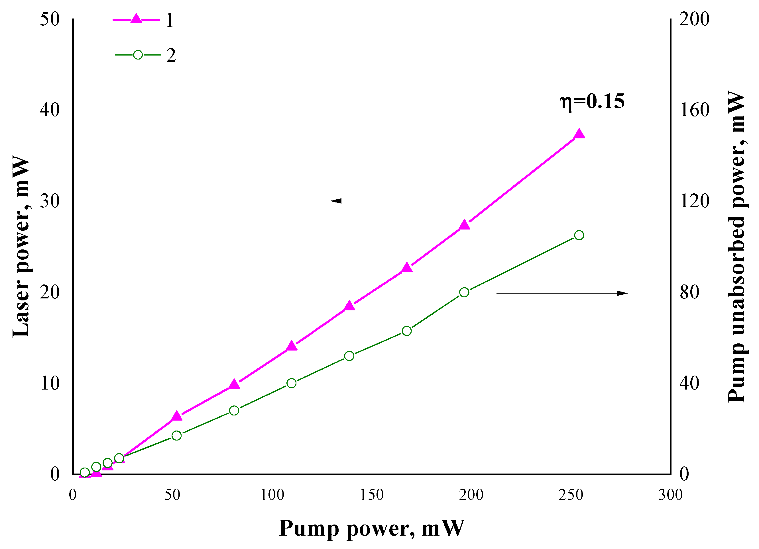
One of the most important characteristics of a fiber laser is the dependence of the output radiation power from the power of the pump radiation coupled into the cavity. Figure 7 shows the power dependencies for the 974.5 nm-wavelength pumping case. The graph “1” in Figure 7 attributes to the laser output power depending on the pump radiation coupled power. The second graph “2” reveals the unabsorbed pump power (i.e., pump radiation passed through the cavity) versus the coupled pump power.
The analysis of Figure 7 gives us a result of the differential power efficiency (or slope efficiency, η) of the “random” laser: 0.15. It should be noted that a rather significant part (~40%) of the pump radiation was not absorbed in the cavity and therefore the η value was not maximum.
A relatively simple and convenient way for increasing the slope efficiency of a “random” cavity without the risk of lasing instability escalation is the extension of this cavity by the single separate highly reflective FBG [25]. The reflection peak of such FBGs in this case must be wavelength matched exactly with the reflection maximum of the weakly reflective FBG array (i.e., lasing wavelength), which form a basic “random” cavity. The FBG used in the present work had a length of 10 mm and was inscribed in a photosensitive (germanosilicate) OF, with waveguide characteristics close to the parameters of the studied active OF: the cutoff wavelength was 910 nm, the refractive index difference was 0.014. This FBG with a 90% reflection on the wavelength of 1548 nm was spliced to the 7-m-long “random” cavity from the side opposite to the direction of launch the pump radiation. The optical loss at the splicing point did not exceed 0.1 dB.
As seen in the Figure 8 (curves “1” and “2”), the modification “random” cavity by the 90%-reflective FBG did not lead to any significant changes in the shape of the emission spectrum. The slight difference in the peak wavelength of the “1” and “2” spectra may be due to the temperature effects.
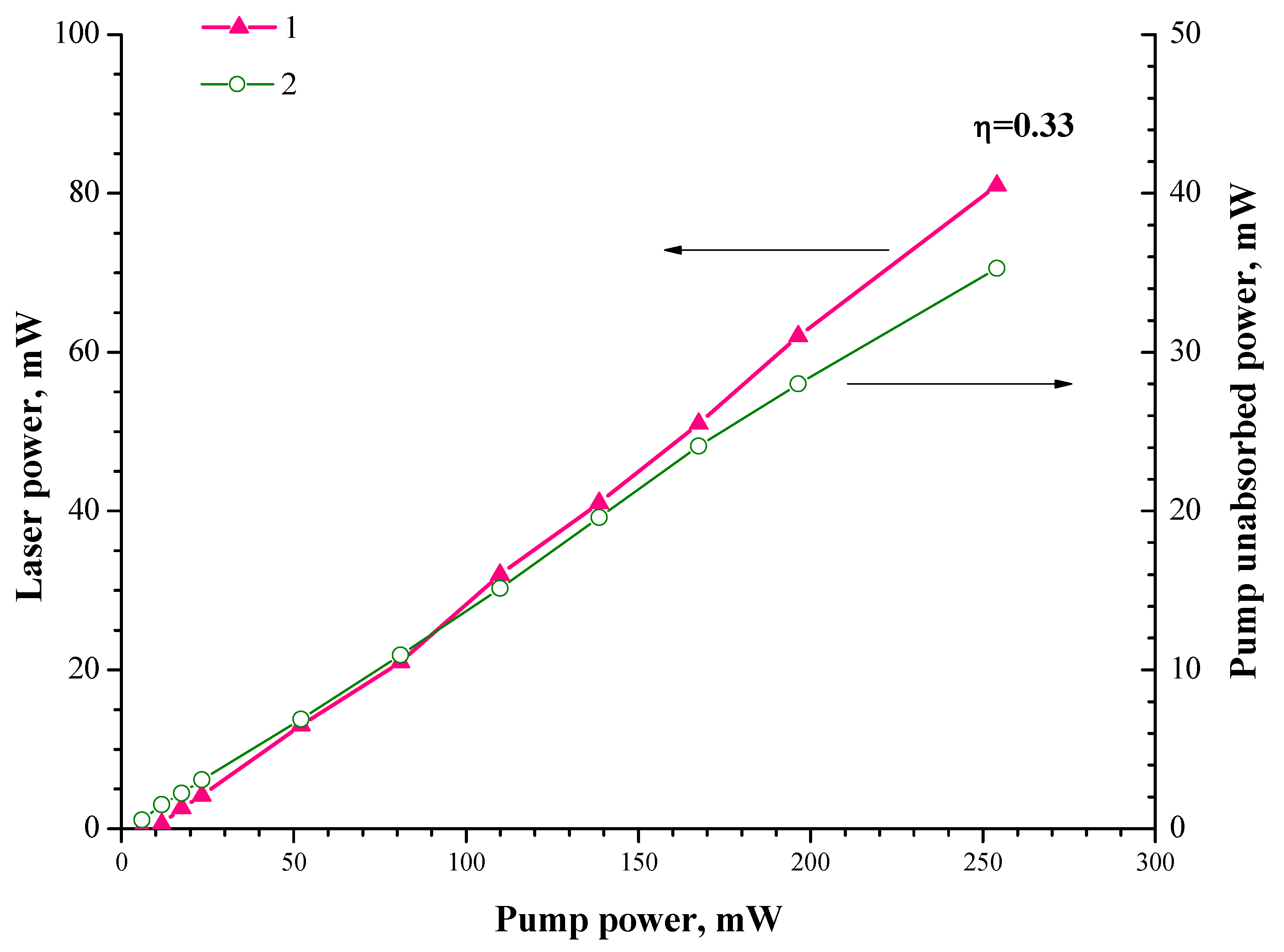
On the other hand, the “random” cavity modified with a 90%-reflective FBG demonstrated a twofold increase in the output power and slope efficiency (η = 0.33) at the same values of the pump power (see Figure 9, graph “1”). This can be explained by the more efficient absorption of the pump radiation in the cavity modified by the FBG (compare graphs “2” in the Figure 7 and Figure 9), despite the fact that its length (7 m) did not change much. It is extremely important to point out that lasing with a 90%-reflective FBG was unreachable in configuration with a conventional 7-m-long active OF. The lasing was possible only when this FBG was attached to the array of weakly reflective FBGs, i.e., segment of the artificial Rayleigh fiber.
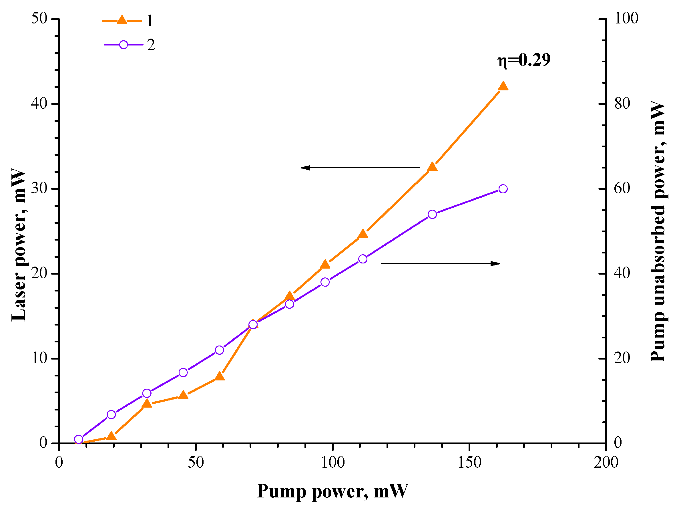
In the case of 1485 nm wavelength pumping, the influence of the cavity extension by the 90%-reflective FBG was much more significant. Importantly, the lasing threshold in the “pristine” 7-m-long cavity (without the 90%-reflective FBG) was not achieved at any pumping power level. On the contrary, as shown in the Figure 10, the same laser cavity modified by the 90%-reflective FBG demonstrated a good lasing threshold (~10 mW of pumping power) and slope efficiency (η = 0.29), which was comparable in value to the slope efficiency at the 974.5 nm wavelength pumping (η = 0.33).
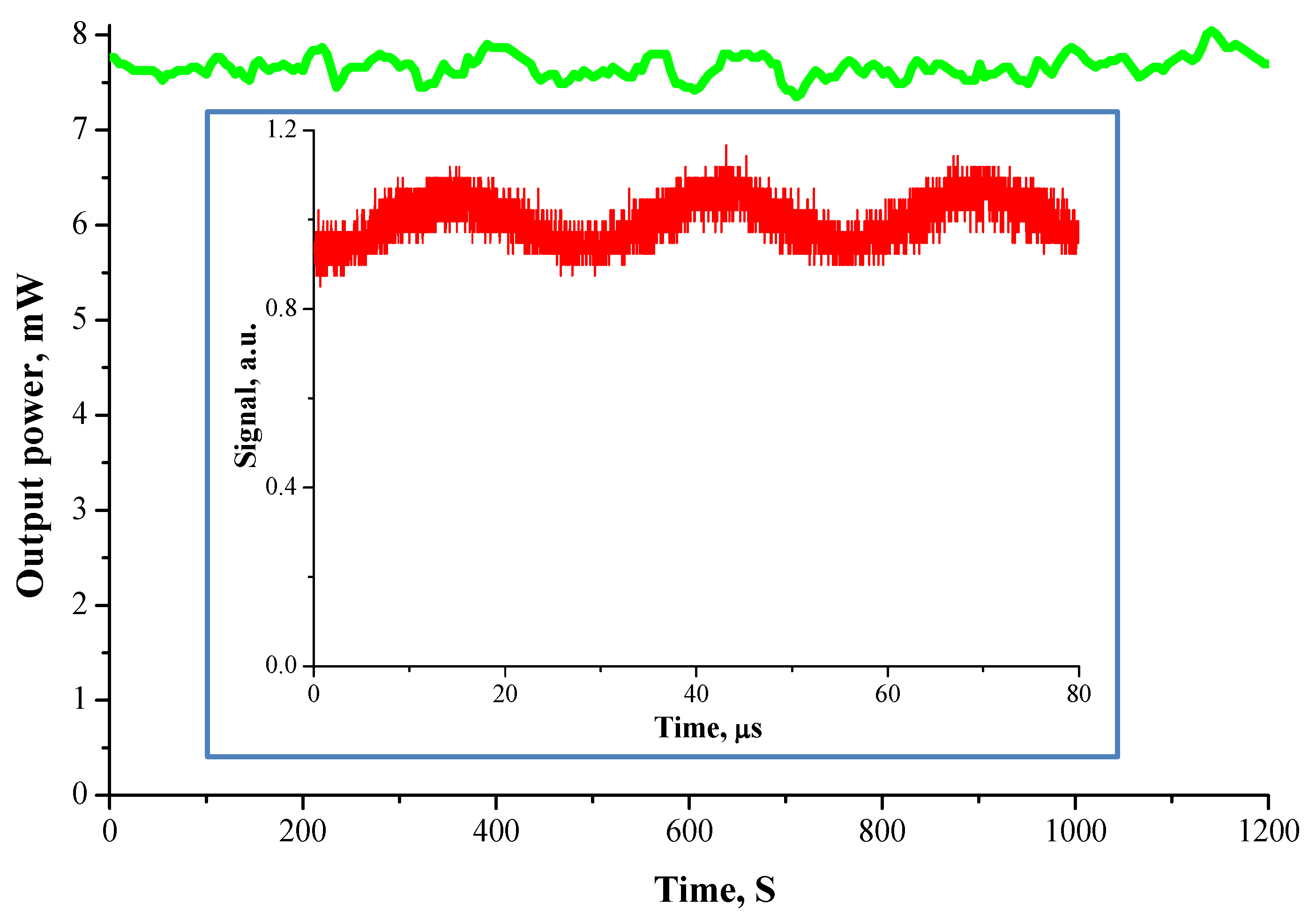
The long-term laser power stability has been studied. The laser cavity extended by the 90%-reflective FBG was pumped at the 974.5 nm wavelength with a 50 mW input power level. Figure 11 displays the laser’s output power value with a long time duration. It can be concluded that the laser power is sufficiently stable at a constant external temperature (295 K).
It was also found that the studied laser operated strictly in a continuous-wave (CW) mode, without any self-pulsing (such as a Q-switch). This result is in good agreement with our previous works [19,20,21,22,25]. The CW laser operation can be explained by the contribution of the dynamic grating formation [19,20]. On the other hand, one can see in the inset of Figure 11 a weak oscillation with a frequency of 35–40 kHz. This behavior and the oscillation frequency value, however, are typical for Er-doped fiber lasers and it was investigated earlier in publications [21,31,32].
Figure 12 shows the resulting spectrum of the laser emission linewidth measurement by using the self-heterodyne method [20,33]. This measurement was carried out via a radio-frequency (RF) FSH8 Rohde and Schwarz spectrum analyzer connected with an unbalanced Mach–Zehnder interferometer involving the 40 MHz frequency electro-optic modulator and a 50-km-long fiber delay line. The laser was pumped at the 976 nm wavelength with a power level of 72 mW. The shown RF spectrum has resulted of 20 times averagement of the laser output signal during the scanning time of 374 ms. The measured RF spectrum has a good fit with a Lorentz function and so the linewidth value was determined as about of 550 Hz at the −3 dB intensity level.

4. Discussion

For the first time, comparative studies of the random laser efficiency with a cavity based on the artificial Rayleigh fibers in pumping modes at wavelengths of 974.5 and 1485 nm have been carried out. Initially, for the experiments, the OF cavity length was chosen as 7 m by a balance between the FBG array reflection and erbium ion absorption. When using a source with a wavelength of 974.5 nm in the cavity with a length of 7 m, it leads to the appearance of lasing at a wavelength of 1548 nm at a rather low threshold value of an injected pump power, about 7 mW. On the contrary, in the same cavity, when it was pumped by the source with a wavelength of 1485 nm, the lasing threshold would not be reached. In the cavity modified with a 90% FBG, the laser generation was obtained in the pumping mode at the wavelength of 1485 nm. The slope efficiency of the modified “random” cavity in the pumping modes at wavelengths of 974.5 and 1485 nm turned out to be comparable: 0.33 and 0.29, respectively.
The effect of the significant (many times) increase in a laser efficiency in a “random” cavity, modified by adding a single FBG with a reflection coefficient of 90%, has been found. Such an effect can be explained by changing the lasing configuration from open to half-open cavity configuration [34] that increases a length of laser’s cavity, returning lasing power from “forward” direction to “backward” direction and finally reducing lasing threshold. The absence of lasing at 1485 nm without 90% FBG can be explained by non-optimal pumping conditions, because the fiber’s cutoff wavelength is 900 nm, thus, it means that the pumping process of the active core at 1485 nm is a multimode. Once again, it clearly demonstrates the advancement of the highly reflective FBG extension in such laser configurations. This FBG also functions as a highly efficient wavelength selector in the case of heterogeneity in the length of the artificial Rayleigh fiber, as noted earlier [25].
The effect of long-time changes in the level of the output signal shown in Figure 11 is explained by not using the polarization maintaining items to produce such a laser. It causes problems of long-time lasing stability. Our next step will be a random laser based on the polarization maintaining items (include a single polarization artificial Rayleigh fiber) to prevent such problems in the future. A later optimization conversion efficiency is possible by the optimal concentration of the erbium ions, cavity length, FBG contrast (a reflection level of artificial Rayleigh fiber) and the wavelength of lasing (for example, 1530 nm is the wavelength of the maximum amplification).
The investigated laser scheme operates in continuous-wave mode. Such a continuous lasing mode is typical for random lasers [2]. The measured lasing single-frequency emission linewidth is about 550 Hz, which fits with our previous works [20,21]. Such a result is opposite to earlier works concerning many FBGs inscribed in the erbium doped OF [5], where multiple modes of lasing take place. The difference explained by that cavity in our case consists of many FBGs that totally coat OF and form a continuous reflection track similar to the Rayleigh scattering, instead of a set of discrete FBGs (point reflectors) as were previously used in pioneering works. Single frequency lasing is also explained by the contribution of dynamic grating formation, which possibly support the main lasing mode and operates as a dynamic filter—as described in our previous publications [19,20].

5. Conclusions

It has been demonstrated that an erbium-doped fiber laser with a “random” resonator is capable of operating at room temperature in a continuous-wave mode for a long time (at least tens of minutes), which is extremely important from the point of view of the prospects for its use as a fiber source of high coherence optical radiation. The feature of the described laser configurations is a high efficiency (up to 33%) with a combination of narrow linewidth (~550 Hz) radiation.
The proposed random laser is a simple, compact, cost-effective and highly efficient solution for many practical applications such as telecommunication and fiber-optic sensing.

Author Contributions

Conceptualization, S.P., A.R. and D.L.; methodology, S.P., V.V., A.K., I.V. and V.I.; software, D.R. and S.P.; validation, Y.C.; investigation, A.R., S.P., A.B., A.S. and D.R.; data curation, S.P. and Y.C.; writing—original draft preparation, A.R. and S.P.; supervision, A.R. and S.P.; project administration, O.B.; funding acquisition, O.B.; Writing—review and editing, S.P. All authors have read and agreed to the published version of the manuscript.

Funding

The work was carried out within the framework of the Kotelnikov IRE RAS state task.

Institutional Review Board Statement

Not applicable.

Informed Consent Statement

Not applicable.

Data Availability Statement

Not applicable.

Conflicts of Interest

The authors declare no conflict of interest.

References

  1. Fotiadi, A.A.; Kiyan, R.V. Cooperative stimulated Brillouin and Rayleigh backscattering process in optical fiber. Opt. Lett. 1998, 23, 1805–1807. [Google Scholar] [CrossRef]
  2. Turitsyn, S.; Babin, S.; El-Taher, A.; Harper, P.; Churkin, D.; Kablukov, S.; Ania-Castañón, J.; Karalekas, V.; Podivilov, E. Random distributed feedback fibre laser. Nat. Photonics 2010, 4, 231. [Google Scholar] [CrossRef]
  3. Fotiadi, A.A. Random lasers: An incoherent fibre laser. Nat. Photonics 2010, 4, 204–205. [Google Scholar] [CrossRef]
  4. Turitsyn, S.K.; Babin, S.A.; Churkin, D.V.; Vatnik, I.D.; Nikulin, M.; Podivilov, E.V. Random distributed feedback Fibre lasers. Phys. Rep. 2014, 542, 133–193. [Google Scholar] [CrossRef]
  5. Lizárraga, N.; Puente, N.P.; Chaikina, E.I.; Leskova, T.A.; Méndez, E.R. Single-mode Er-doped fiber random laser with distributed Bragg grating feedback. Opt. Express 2009, 17, 395–404. [Google Scholar] [CrossRef] [PubMed]
  6. Skvortsov, M.I.; Abdullina, S.R.; Vlasov, A.A.; Zlobina, E.A.; Lobach, I.A.; Terentyev, V.S.; Babin, S.A. FBG array-based random distributed feedback Raman fibre laser. Quantum Electron. 2017, 47, 696. [Google Scholar] [CrossRef]
  7. Bronnikov, K.; Wolf, A.; Yakushin, S.; Dostovalov, A.; Egorova, O.; Zhuravlev, S.; Semjonov, S.; Wabnitz, S.; Babin, S. Durable shape sensor based on FBG array inscribed in polyimide-coated multicore optical fiber. Opt. Express 2019, 27, 38421. [Google Scholar] [CrossRef] [Green Version]
  8. Przhiialkovskii, D.; Butov, O. High-precision point-by-point fiber Bragg grating inscription. Results Phys. 2021, 30, 104902. [Google Scholar] [CrossRef]
  9. Askins, C.G.; Putnam, M.A.; Williams, G.M.; Fiebele, E.J. Stepped-wavelength optical-fiber Bragg grating arrays fabricated in line on a draw tower. Opt. Lett. 1994, 19, 147–149. [Google Scholar] [CrossRef]
  10. Guo, H.; Tang, J.; Li, X.; Zheng, Y.; Yu, H.; Yu, H. On-line writing identical and weak fiber Bragg grating arrays. Chin. Opt. Lett. 2013, 11, 030602. [Google Scholar]
  11. Zaitsev, I.; Butov, O.; Voloshin, V.; Vorob’ev, I.; Vyatkin, M.; Kolosovskii, A.; Popov, S.; Chamorovskii, Y. Optical Fiber with Distributed BraggType Reflector. J. Comm. Technol. Elec. 2016, 61, 639. [Google Scholar] [CrossRef]
  12. Popov, S.; Butov, O.; Kolosovski, A.; Voloshin, V.; Vorob’ev, I.; Vyatkin, M.; Fotiadi, A.; Chamorovski, Y. Optical Fibres with Arrays of FBG: Properties and Application. In Proceedings of the PIERS, IEEE Xplore, 1568, St. Petersburg, Russia, 22–25 May 2017. [Google Scholar]
  13. Chamorovskiy, Y.; Butov, O.; Kolosovskiy, A.; Popov, S.; Voloshin, V.; Vorob’ev, I.; Vyatkin, M. Metal-coated Bragg grating reflecting fibre. Opt. Fiber Technol. 2017, 34, 30. [Google Scholar] [CrossRef]
  14. Chamorovskiy, Y.; Butov, O.; Kolosovskiy, A.; Popov, S.; Voloshin, V.; Vorob’ev, I.; Vyatkin, M.; Odnobludov, M. Long tapered fiber with array of FBG. Opt. Fiber Technol. 2019, 50, 95. [Google Scholar] [CrossRef]
  15. Popov, S.; Butov, O.; Kolosovskii, A.; Voloshin, V.; Vorob’ev, I.; Isaev, V.; Vyatkin, M.; Fotiadi, A.; Chamorovsky, Y. Optical fibres and fibre tapers with an array of Bragg gratings. Quantum Electron. 2019, 49, 1127. [Google Scholar] [CrossRef]
  16. Kharasov, D.; Bengalskii, D.; Vyatkin, M.; Nanii, O.; Fomiryakov, E.; Nikitin, S.; Popov, S.; Chamorovsky, Y.; Treshchikov, V. Extending the operation range of a phase-sensitive optical time-domain reflectometer by using fibre with chirped Bragg gratings. Quantum Electron. 2020, 50, 510. [Google Scholar] [CrossRef]
  17. Popov, S.; Chamorovsky, Y.; Mégret, P.; Zolotovskii, I.; Fotiadi, A. Brillouin Random Lasing in Artifice Rayleigh Fiber. In Proceedings of the ECOC, IEEE Xplore, 1, Valensia, Spain, 27 September–1 October 2015. [Google Scholar]
  18. Popov, S.; Butov, O.; Chamorovskiy, Y.; Isaev, V.; Kolosovskiy, A.; Voloshin, V.; Vorob’ev, I.; Vyatkin, M.; Mégret, P.; Odnoblyudov, M.; et al. Brillouin lasing in single-mode tapered optical fiber with inscribed Fiber Bragg Grating Array. Results Phys. 2018, 9, 625. [Google Scholar] [CrossRef]
  19. Popov, S.; Butov, O.; Chamorovski, Y.; Isaev, V.; Mégret, P.; Korobko, D.; Zolotovskii, I.; Fotiadi, A. Narrow linewidth short cavity Brillouin random laser based on Bragg grating array fiber and dynamical population inversion gratings. Results Phys. 2018, 9, 806–808. [Google Scholar] [CrossRef]
  20. Popov, S.; Butov, O.; Bazakutsa, A.; Vyatkin, M.; Chamorovskii, Y.; Fotiadi, A. Random lasing in a short Er-doped artificial Rayleigh fiber. Results Phys. 2020, 16, 102868. [Google Scholar] [CrossRef]
  21. Popov, S.M.; Butov, O.V.; Bazakutsa, A.P.; Vyatkin, M.Y.; Chamorovskiy, Y.K.; Panajotov, K.; Fotiadi, A.A. Narrow linewidth random laser based on short Er-doped artifice Rayleigh fiber. Proc. SPIE 2020, 11357, 318–327. [Google Scholar]
  22. Rybaltovsky, A.; Popov, S.; Lipatov, D.; Umnikov, A.; Abramov, A.; Morozov, O.; Ryakhovskiy, D.; Voloshin, V.; Kolosovskii, A.; Vorob’ev, I.; et al. Photosensitive Yb-doped germanophosphosilicate artificial Rayleigh fibers as a base of random lasers. Fibers 2021, 9, 53. [Google Scholar] [CrossRef]
  23. Skvortsov, M.I.; Wolf, A.A.; Dostovalov, A.V.; Egorova, O.N.; Semjonov, S.L.; Babin, S.A. Narrow-Linewidth Er-Doped Fiber Lasers With Random Distributed Feedback Provided By Artificial Rayleigh Scattering. J. Light. Technol. 2022, 6, 1829–1835. [Google Scholar] [CrossRef]
  24. Skvortsov, M.I.; Abdullina, S.R.; Wolf, A.A.; Dostovalov, A.V.; Churin, A.E.; Egorova, O.N.; Semjonov, S.L.; Proskurina, K.V.; Babin, S.A. Single-frequency erbium-doped fibre laser with random distributed feedback based on disordered structures produced by femtosecond laser radiation. Quantum Electron. 2021, 51, 1051–1055. [Google Scholar] [CrossRef]
  25. Rybaltovsky, A.; Popov, S.; Ryakhovskiy, D.; Abramov, A.; Umnikov, A.; Medvedkov, O.; Voloshin, V.; Kolosovskii, A.; Vorob’ev, I.; Chamorovskiy, Y.; et al. Random Laser Based on Ytterbium-Doped Fiber with a Bragg Grating Array as the Source of Continuous-Wave 976 nm Wavelength Radiation. Photonics 2022, 9, 840. [Google Scholar] [CrossRef]
  26. Popov, S.M.; Butov, O.V.; Kolosovskii, A.O.; Voloshin, V.V.; Vorob’ev, I.L.; Isaev, V.A.; Ryakhovskii, D.V.; Vyatkin, M.Y.; Rybaltovskii, A.A.; Fotiadi, A.A.; et al. Optical fibres with an inscribed fibre Bragg grating array for sensor systems and random lasers. Quantum Electron. 2021, 51, 1101–1106. [Google Scholar] [CrossRef]
  27. Spirin, V.; López-Mercado, C.; Kinet, D.; Mégret, P.; Zolotovskiy, I.; Fotiadi, A. Single longitudinal-mode brillouin fiberlaser passively stabilized at pump resonance frequency with dynamic population inversion grating. Laser Phys. Lett. 2013, 10, 015102. [Google Scholar] [CrossRef]
  28. Lobach, I.A.; Drobyshev, R.V.; Fotiadi, A.A.; Podivilov, E.V.; Kablukov, S.I.; Babin, S.A. Open-cavity fiber laser with distributed feedback based on externally or self-induced dynamic gratings. Opt. Lett. 2017, 42, 4207–4210. [Google Scholar] [CrossRef]
  29. Web-Site of Optosystems. Available online: https://optosystems.ru/en/product/cl-5000/ (accessed on 22 May 2023).
  30. Soller, B.; Gifford, D.; Wolfe, M.; Froggatt, M. High resolution optical frequency domain reflectometry for characterization of components and assemblies. Opt. Express 2005, 13, 666. [Google Scholar] [CrossRef] [Green Version]
  31. Smirnov, A.M.; Bazakutsa, A.P.; Chamorovskiy, Y.K.; Nechepurenko, I.A.; Dorofeenko, A.V.; Butov, O.V. Thermal Switching of Lasing Regimes in Heavily Doped Er3+ Fiber Lasers. ACS Photonics 2018, 5, 5038–5046. [Google Scholar] [CrossRef] [Green Version]
  32. Skvortsov, M.; Wolf, A.; Dostovalov, A.; Vlasov, A.; Akulov, V.; Babin, S. Distributed feedback fiber laser based on a fiber Bragg grating inscribed using the femtosecond point-by-point technique. Laser Phys. Lett. 2018, 15, 035103. [Google Scholar] [CrossRef]
  33. Richter, L.E.; Mandelberg, H.I.; Kruger, M.S.; Mcgrath, P.A. Linewidth determination from self-heterodyne measurements with subcoherence delay times. IEEE J. Quantum Electron. 1986, 22, 2070–2074. [Google Scholar] [CrossRef]
  34. Zhang, W.L.; Rao, Y.J.; Zhu, J.M.; Wang, Z.X.; Jia, X.H. Low threshold 2nd-order random lasing of a fiber laser with a half-opened cavity. Opt. Express 2012, 20, 14400–14405. [Google Scholar] [CrossRef] [PubMed]
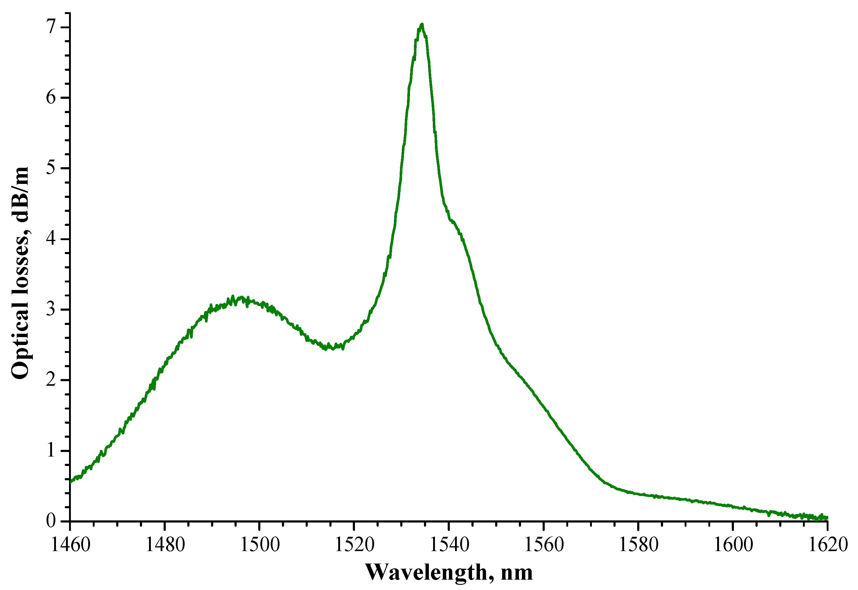
Figure 1. Transmission spectrum of the optical fiber in the wavelength range of 1460–1620 nm.
Photonics 10 00748 g001
Figure 2. Spectral dependences of the small-signal gain in the wavelength range 1525–1610 nm, measured in the fiber pumping mode at a wavelength of 976 nm (“1”) and 1490 nm (“2”).
Photonics 10 00748 g002
Figure 3. Frequency reflectogram (OFDR) of the experimental 50%-filled weakly reflective FBG array with a central reflection wavelength at 1548 nm.
Photonics 10 00748 g003
Figure 4. Optical reflection spectrum of the 7-m-long weakly reflective FBG array.
Photonics 10 00748 g004
Figure 5. The scheme of the experimental setup: 1– laser cavity; 2–wavelength-division multiplexer (WDM); 3–laser diodes; 4–optical isolator; 5–optical spectrum analyzer; 6–optical powermeters; 7–highly reflective FBG.
Photonics 10 00748 g005
Figure 6. Emission spectra of the conventional (i.e., non-containing weakly reflective FBG array) active OF (“1”) and the artificial Rayleigh fiber (“2”), obtained at the same power level (~30 mW) of the 976 nm wavelength pump. “ASE”—spontaneous emission, “lasing”—laser generation.
Photonics 10 00748 g006
Figure 7. Output power (“1”) of the “random” laser cavity and the unabsorbed pump power (“2”) versus the coupled pump power with a wavelength of 974.5 nm. Pink line–left scale. Black line right scale.
Photonics 10 00748 g007
Figure 8. Emission spectra of the “random” laser cavities obtained at a 974.5 nm wavelength pumping (coupled power of 30 mW): the pristine cavity (1) and the same cavity modified by the 90%-reflective FBG (2).
Photonics 10 00748 g008
Figure 9. Output power (“1”) of the “random” laser cavity, modified with FBG, and the unabsorbed pump power (“2”) versus the coupled pump power with a wavelength of 974.5 nm. Red line—left scale. Green line—right scale.
Photonics 10 00748 g009
Figure 10. Output power (“1”) of the “random” laser cavity, modified with FBG, and the unabsorbed pump power (“2”) versus the coupled pump power with a wavelength of 1485 nm. Orange line—left scale. Violet line—right scale.
Photonics 10 00748 g010
Figure 11. Time dependence of the laser’s output power (green). Inset—oscilloscope trace (red).
Photonics 10 00748 g011
Figure 12. Averaged RF spectrum (“1”) and fitted by the Lorentz function (“2”).
Photonics 10 00748 g012
Disclaimer/Publisher’s Note: The statements, opinions and data contained in all publications are solely those of the individual author(s) and contributor(s) and not of MDPI and/or the editor(s). MDPI and/or the editor(s) disclaim responsibility for any injury to people or property resulting from any ideas, methods, instructions or products referred to in the content.