Article

Design and Simulation Analysis of Piezoelectric Ceramic Tube-Based Fiber Optic Nutator Applied to an Intersatellite Laser Communication System

1
Xi’an Institute of Optics and Precision Mechanics, Chinese Academy of Sciences, Xi’an 710119, China
2
University of Chinese Academy of Sciences, Beijing 100049, China
3
Key Laboratory of Space Precision Measurement Technology, Xi’an Institute of Optics and Precision Mechanics, Chinese Academy of Sciences, Xi’an 710119, China
*
Author to whom correspondence should be addressed.
Photonics 2023, 10(7), 769; https://doi.org/10.3390/photonics10070769
Submission received: 30 May 2023 / Revised: 30 June 2023 / Accepted: 2 July 2023 / Published: 4 July 2023
(This article belongs to the Section Optical Communication and Network)

Abstract

:
The signal-receiving end of acquisition, pointing, and tracking (APT) systems applied to intersatellite laser communication terminals usually uses a fast-steering mirror (FSM) to control the fiber-coupling process, has a complex structural design, and induces large errors in the nonideal coaxial optical path. Herein, we propose a fiber-optic nutator using a piezoelectric ceramic tube (PCT) as the driving unit that allows scanning in the focal plane of the light signal to achieve active fiber coupling in the APT system. Specifically, this article describes the structural design principle of a PCT-based fiber optic nutator, establishes a simulation model of the mechanism, and proves the correctness of the simulation model by measuring the deflection angle of a PCT based on a parallel light collimator. The minimum accuracy of the designed nutator was 0.145 μm, the maximum nutation radius R was 20.09 μm, and the maximum nutation bandwidth was 20 kHz, as determined through simulation. Finally, the design parameters of the nutator were evaluated. The PCT-based fiber optic nutator, which met the design parameters, structurally replaced the fiber optic coupling component FSM and fine tracking camera in conventional APT systems successfully. Therefore, the PCT-based fiber optic nutator allows the active coupling control of signal light to a single-mode fiber (SMF) based on energy feedback on a theoretical basis and promotes the lightweight design of relay optical paths in APT systems. In addition, with future work in optimization of the nutation control algorithm, the scanning range and accuracy of the nutator can be improved.

1. Introduction

In inter-satellite laser communication, the fiber coupling efficiency of an acquisition, pointing, and tracking (APT) system of satellite terminals can directly affect the information transmission efficiency of satellites [1,2,3]. The optimization of the fiber coupling structure design of the relay optical path of an APT system is becoming an important topic of research [4,5]. For a traditional APT system, the communication-receiving unit of the relay optical path usually uses a fast-steering mirror (FSM) and coarse–fine tracking cameras to realize the coupling of the signal light to the receiving fiber [6,7,8]. The basic principle is to compensate the FSM’s deflection angle with adaptive feedback from the beacon and light signal position information captured by the coarse and fine tracking cameras, respectively [9,10,11]. The FSM-based APT relay optical path has a high bandwidth and a wide field of view [12]; however, the error in the nonideal coaxial optical path is large, and the structure is complex. Owing to the fixed position of the receiving fiber, it is difficult to capture the light signal on the fiber end, which limits the response speed and comprehensive efficiency of fiber coupling.
Another FSM-based APT system uses a fiber optic nutation controller (FONC) to replace the fine tracking camera [13,14,15]; this controller operates via a fiber-assisted movement mechanism based on the principle of energy feedback compensation [16,17]. When the FSM is compensated for fiber coupling, the FONC drives the receiving fiber end face to perform a uniform circular scan in the focal plane of the incident light—this shortens the alignment time of the FSM and improves the fiber coupling efficiency of the APT system. From 1989 to 1992, Swanson and Knibbe, from the MIT Lincoln Laboratory, proposed a laser-nutation-based spatial optical to single-mode fiber coupling system using electromagnetic materials to drive the fiber end face in order to perform a fixed radius nutation scan at the focal plane of the receiving lens; this setting improved the coupling efficiency to 63% [18,19,20,21]. In 2014, Luo and Gen from the Institute of Optoelectronics Technology, Chinese Academy of Sciences, proposed an adaptive fiber optic collimator (AFOC)-based optical coupling system, which used dual piezoelectric plates and a flexible hinge to construct the FONC [22,23]. The piezoelectric ceramic tube (PCT) is also applied in the manufacturing of the FONC because of its lightweight construction and high-motion accuracy [24,25,26]. It has already been used extensively in fields such as atomic force microscope probe control [27,28] and medical endoscopy fiber-optic probe scanning [29,30]. In 2002, Dreischer of Contraves Space AG, Switzerland, used a 1.5 mm diameter PCT to drive a single fiber in the signal optical focal plane for nutation scanning to accelerate the fiber coupling process of the FSM, achieving the maximum operating bandwidth of 5 kHz and fiber chapter motion resolution of 20 nm [31]. In 2019, Zhao, Shanghai Institute of Optics and Fine Mechanics, Chinese Academy of Sciences, used a PCT as an auxiliary motion unit at the receiver end of the signal light fiber coupling with a fixed chapter motion radius of 1.1 µm and a maximum chapter motion bandwidth of 2 kHz [32]. In these application scenarios, the fiber can only allow fixed radius nutation; because of this, the FONC does not have the function of active tracking scanning and can only be used to follow an auxiliary mechanism for the FSM in the fiber coupling process. The linked structure of FSM and FONC makes the APT system more complex and relatively larger in size and mass.
Based on the lightweight design of the communication receiving branch of the APT system, in this study, a fiber optic nutator with a PCT as the active control unit is developed. This nutator can replace the FSM as well as fine tracking camera in the signal-receiving branch and achieves active fiber coupling of light signals and SMF in the APT system independently. The remainder of the article is organized as follows. Section 2 presents the mechanical structural design of the fiber optic nutator and describes the nutation principle of the PCT. Section 3 includes the simulation and experimental verification of the fiber optic nutator, including the simulation theory of the PCT and the simulation of the fiber optic nutator’s natural frequency and maximum nutation radius. Section 4 discusses the design parameter criteria of the PCT-based fiber optic nutator, including the relay optical path for the APT system. Section 5 presents the conclusions of the study.

2. Structural Design of the PCT-Based Fiber Optic Nutator

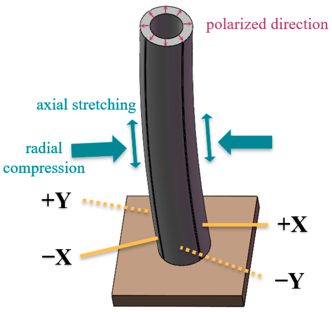
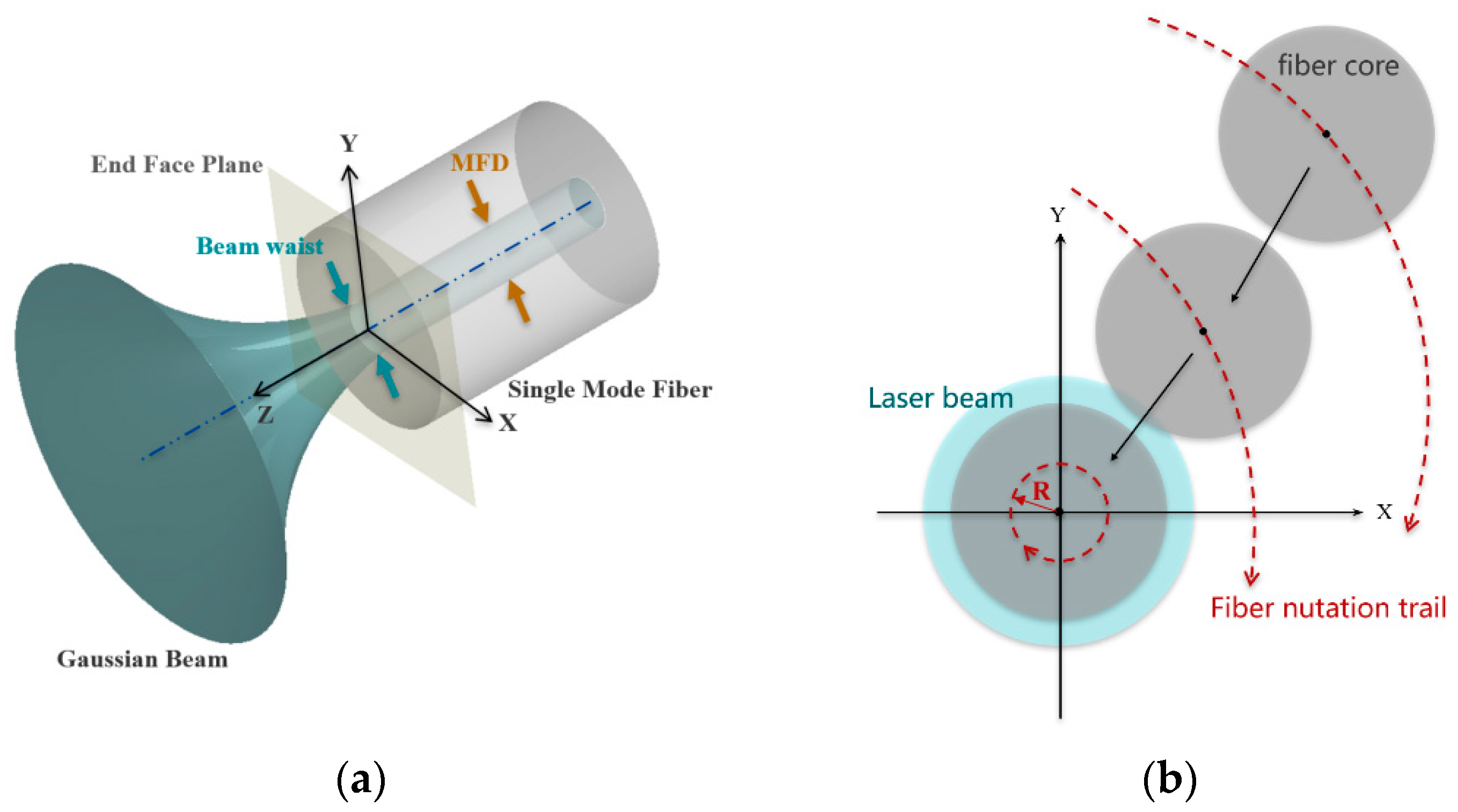
2.1. Principle of Operation of PCT-Based Fiber Optic Nutator

A PCT is a thin hollow tube made of a radially polarized piezoelectric material with a continuous internal electrode and four identical external electrodes that are insulated from each other. Because of the coupling of the dielectric and elastic properties of the piezoelectric crystal [33], when a positive voltage is applied to one of the external electrodes, the PCT wall at the corresponding position induces radial compression and axial stretching, causing a small vertical contraction and large lateral deflection of the tube tip, as shown in Figure 1. The lateral deflection range of the tube tip is doubled by applying an equivalent negative voltage to the external electrode.
The vertical contraction displacement of the PCT was <1% of the transverse deflection displacement. When the four external electrodes apply the voltage with the function expression as shown in Equation (1) at the same time, the tube top can be regarded as a nutation motion with radius R = αV0 and center position (x = φ1, y = φ2) in the two-dimensional plane.
V x   t = ± α V 0 cos 2 π F t + φ 1 V y t = ± α V 0 sin 2 π F t + φ 2
where V0 is the power input voltage, α is the voltage amplification of the PCT amplifier, F is the chapter motion bandwidth, and φ1, φ2 are the initial phases in the x- and y-directions, respectively. Adjusting the magnitude of V0 will change the maximum radius of the PCT, while the values of φ1 and φ2 determine the real-time position of the center of the PCT in the scanning plane.
The collimated signal light has a Gaussian intensity profile, and its fiber-coupling principle is explained in Figure 2a. To obtain high-coupling efficiency, the beam waist of the Gaussian beam must be located at the fiber end face, the center of the beam waist needs to coincide with the center of the single-mode fiber, and the diameter of the beam waist should be equal to the Mode Field Diameter (MFD) of the single-mode fiber. The PCT drives the single-mode fiber movement to the position that satisfies the above conditions by means of nutation scanning, as shown in Figure 2b. Initially, the fiber end face was not in contact with the incident light, and the fiber coupling efficiency was 0. By adjusting the control voltage, the radius of the fiber end face and the direction of the circular motion were continuously changed until the fiber end face started to contact the incident light, and the system received an optical power signal with a value greater than 0. Then, the input voltage of the piezoelectric tube was compensated by energy feedback to further improve the degree of coincidence between the fiber end face and signal light Airy spot until the highest coupling efficiency was obtained.

2.2. Mechanical Structural Design

Based on the principle of PCT actuation, the proposed fiber optic nutator uses a PCT as an actuator to control the active motion of a signal-receiving fiber in the light-coupling process. As shown in Figure 3, the main structure of the mechanism included an optical lens, PCT driver, and metal housing for fastening the connection. The collimated signal light was focused on the end face of the signal-receiving fiber by the optical lens at the front of the device, the SMF together with the fixed insert was fixed to the top of the piezoelectric tube by a fiber curing adhesive, and the fiber end face was always located at the center of the hollow tube cavity. The PCT was secured to a clamping ring at the bottom of the metal housing, and a solder wire was led from the end of the device along the fiber end. By applying an alternating voltage to the four external electrodes, the end face of the PCT can be driven along a circular trajectory, thus allowing the fiber end face to perform a nutation scan.
As the active control unit of fiber optic coupling at the signal-receiving end of the APT system, the main design parameters of the PCT-based fiber optic nutator include the maximum nutation bandwidth F, nutation accuracy η, and maximum nutation scan radius R. F is the maximum operating frequency that can be achieved by the mechanism, η is the minimum resolution that fiber nutation can achieve, and R determines the nutation scan range of the signal-receiving fiber. A set of these parameters can effectively characterize the fiber coupling capability of the mechanism.
The structure type of piezoelectric ceramic and its corresponding voltage amplifier determine the nutation bandwidth of the fiber optic nutator. The PCT was made of PIC-255 modified with lead zirconate titanate; it has an outer diameter of 3.2 mm, a wall thickness of 0.5 mm, and a tube length of 30 mm. Using E-413.30 multi-channel amplifier provided by PI company as the piezo tube actuator, the theoretical maximum bandwidth can reach 20 kHz. To avoid the resonance stress on the precision and structural stability of the nutation, the nutation bandwidth of the PCT must be far away from the inherent frequency of the PCT-based fiber optic nutator [34]; the details of the analysis will be elaborated in Section 3.3.
According to the piezoelectric theory, the deformation of the piezoelectric ceramic material is linearly related to the input voltage; therefore, the theoretical displacement accuracy of the PCT can reach infinity. In practical applications, the minimum accuracy η of the fiber optic nutator has the following relationship with the minimum angular resolution ωk (unit: °) and tube length Lc (unit: μm) of the PCT multichannel controller:
η = π L c ω k 180
The minimum angular resolution of the PCT multichannel controller selected for this design was 1″ (1″ = 1/3600°). According to the calculation of Equation (2), the minimum accuracy of the PCT driver (η) was 0.145 μm.
The value of R is influenced by the length of the free-moving end of the tube in addition to the shape, size, and material type of the PCT. The maximum operating voltage of the fiber optic mechanism can be adjusted within a certain range by changing the relative positions of the clamping ring and PCT. To obtain the parameters of R and the intrinsic frequency F′, the finite element modeling simulation of the fiber optic mechanism was required.

3. Simulation and Experimental Verification of the PCT-Based Fiber Optic Nutator

The kinematic properties of piezoelectric ceramic structures in a multi-load coupled environment can be simulated quickly and effectively through the finite element analysis (FEA) method [35,36,37]. Here, we propose an FEA simulation model for a PCT-based fiber optic nutator, validate the simulation model with a PCT deflection measurement experiment based on a parallel light collimator, and simulate the maximum radius of motion and intrinsic frequency of the mechanism.

3.1. Simulation Theory of the PCT

In the PCT-based fiber optic nutator, the PCT boundary conditions satisfied the first type of boundary conditions for piezoelectric materials: mechanical free and electrical short circuit (T = 0, E = 0, S ≠ 0, D ≠ 0). Strain S and potential shift D can be described by the first type of piezoelectric equation:
D = d T + ε T E
S = d T E + s E T
and have
d = e s E
D = ε 0 E + χ P
Here, [d] is the piezoelectric strain constant matrix, [d]T is the transposed matrix of [d], and [e] is the piezoelectric stress constant matrix, [εT] is the dielectric constant obtained at constant stress and is called the free dielectric constant, [sE] is the elastic compliance constant matrix, [T] is the material stress matrix, [E] is the electric field strength, and [χ] is the polarizability of the piezoelectric material.
Combining Equations (3)–(6), a simulation model of the PCT nutator based on electrostatic-structural-mechanical coupling can be established using the finite element simulation software.

3.2. Experimental Verification of the Simulation Model

To verify the accuracy of the simulation model of the PCT, the deflection parameters of the PCT nutation were measured experimentally at different voltages, and the experimental results were compared with the corresponding simulation results. Because the PCT had a hollow cylindrical structure, it was difficult to directly measure the deflection displacement at the center of the end face. In this study, based on the measurement principle of a parallel light collimator, the deflection angle of the center normal to the tube end face was used to replace the deflection displacement as the deflection parameter of the PCT. A deflection measurement experiment of the PCT at the specified steady-state voltage was designed, as shown in Figure 4. The PCT was held on a removable insulated polysulfone tool, a miniature reflector was fixed at the top center of the tube, and the tail was connected to the controller and power supply through a solder wire. The entire device was bolted to the optical platform; by adjusting the relative position of the optical platform, the direction of the incident light of the parallel light collimator was along the initial position of the reflector normal vector. When the power supply is fed through the controller with control voltage, the PCT drives the reflector at the top to produce a deflection. According to the principle of geometric optics, the angle of deflection measured by the parallel light collimator is equal to the angle of deflection normal to the center of the PCT.
The devices used for the deflection angle measurement experiments conducted on the PCT are listed in Table 1.
Before the measurement, the parallel light collimator must be calibrated so that the jitter angle reading is stable within 1”. Then, the voltage was amplified 25 times by the controller and applied to the measured PCT, and the deflection angle of the crosshair was measured and recorded once per second at the post-processing end. Because the clamping tool was not rigidly connected to the tube wall, additional deformation caused by residual stress was generated near the contact gap between the PCT and tube during the deflection process. To reduce the interference of additional deformations with the deflection angle measurement, after each steady-state voltage deflection angle measurement, the PCT was allowed to completely release the residual stress, and the collimator was recalibrated before the next voltage measurement session. Considering the hysteresis effect of the piezoelectric ceramic, we uniformly optimized the extraction method for parallel light collimator measurement data. Taking the example of applying ±175 V to a symmetrical set of outer electrodes, the measured deflection angle with time is shown in Figure 5, wherein the voltage is 0 V during the interval of 0–20 s, which means the PCT did not work; in the time period of 20–40 s, the PCT is electrically deflected and gradually reaches a stable state after 2 s owing to the hysteretic effect. The power supply was stopped after 40 s, and the deflection angle rapidly tended to 0. At this time, the measurement data at 23–40 s were selected, and the weighted average was calculated. The average value was considered as the deflection angle of the center normal to the end face of the PCT at the steady-state voltage.
With the center of the circle on the bottom surface of the PCT as the origin, the diameter vectors at the origin, mutually perpendicular to each other, were the x- and y-axes, respectively, and the axial vector was the z-axis to establish a space-rectangular coordinate system. The four external electrodes of the chapter piezoelectric tube were named as ±x-axis and ±y-axis electrodes according to the quadrant position of the x-y plane. Under the condition of applying a 0–250 V steady-state control voltage to the ±x-axis electrodes of the PCT only, the deflection angle data of the normal vector of the end face of the PCT in the x-y plane obtained from the experiment and simulation were acquired; the results are shown in Figure 6a. Similarly, by applying a 0–250 V steady-state control voltage to the ±y-axis electrodes of the PCT only, the experimental and simulated deflection angle data of the normal vector of the end face of the PCT in the x-y plane were obtained; the results are shown in Figure 6b. The curves in Figure 6a,b, which characterize the relative error distribution between the simulated and experimental data, show that the difference between the experimental and simulated results of the PCT deflection under the two conditions does not exceed 5%, confirming that the FEA simulation model of the PCT proposed in this study is valid and accurate.

3.3. Simulation of Natural Frequency and Maximum Nutation Radius of the PCT-Based Fiber Optic Nutator

According to the conclusion in Section 2.2, the operating bandwidth of the PCT driver should not be close to the intrinsic frequency of the PCT-based fiber optic nutator. A modal simulation of the fiber optic nutator was performed; the morphologies of the first six mode vibration shape and the corresponding intrinsic frequencies are shown in Figure 7a–f. The maximum resonance region of the nutator in the 1st and 2nd mode vibration shape was located near the incident lens at the top; the inherent frequencies of the mechanism are F1′ = 2144.3 Hz and F2′ = 2144.5 Hz, respectively. Similarly, in Figure 7c,d, the resonant region is located at the top of the PCT, corresponding to the intrinsic frequencies of the 3rd to 4th mode vibration of F3′ = 2501.1 Hz and F4′ = 2501.3 Hz, respectively. The resonance effects in Figure 7e,f are mainly in the vicinity of the outer wall of the metal protective shell and the top lens support structure of the mechanism, and the inherent frequencies of the 5th and 6th mode vibration are F5′ = 10,481.0 Hz and F6′ = 11,345.0 Hz, respectively. In particular, to ensure that the PCT does not resonate when operating near the minimum operating bandwidth, the minimum operating bandwidth F0 must satisfy the following relationship:
± F 0 2 F n ,   n N +
The fiber optic was fixed by a rigid connection between the insert and inner wall of the ceramic tube; therefore, the scanning radius of the fiber optic nutator could be equated to the radius of deflection of the inner side of the end face of the PCT, Rs. First, the deflection of the fiber optic nutator at the steady-state voltage was analyzed: when the maximum working voltage of ±250 V was applied to the ±x-axis electrodes, the deformation displacement distribution of the PCT driver was as shown in Figure 8a. The maximum deformation area was located at the upper end surface of the PCT. The distribution of deformation displacement of the upper end face is shown in Figure 8b; the maximum deflection region of the end face was located at the outer plating edge, and the minimum deflection region was located at the inner tube wall edge, which indicates the maximum steady-state deflection radius was 20.12 μm for the fiber optic nutator in the x-axis direction. The distribution of deformation displacement on the upper end face of the PCT is shown in Figure 8c. Similarly, when the maximum operating voltage of ±250 V was applied on ±y-axis electrodes, the steady-state maximum deflection radius was 20.12 μm for the fiber optic nutator in the y-axis direction. This confirmed that the maximum deflection of the PCT was equal in all directions under steady-state conditions and satisfied the transient nutation condition.
Next, the voltage functions described in Equation (1) were applied in the ±x and ±y partitions, respectively, and the simulation results of the transient deformation displacement of the upper face of the current PCT driver were obtained by extracting the time step when the minimum value of the deflection radius appeared, as shown in Figure 8d. The nutation radius of the fiber optic nutator at 250 V transient voltage could reach 20.09 μm, that is, the maximum nutation radius of the PCT-based fiber optic nutator was 20.09 μm.
In summary, the minimum accuracy of the PCT-based fiber optic nutator designed in this study was 0.145 μm, R was 20.09 μm, and the maximum nutation bandwidth reached 20 kHz. The 1st–6th order intrinsic frequencies of the mechanism were 2144.3, 2144.5, 2501.1, 2501.3, 10,481.0, and 11,345.0 Hz. To evaluate whether the mechanism can meet the fiber coupling control requirements of the APT system, it was necessary to derive the design parameter criteria for the PCT-based fiber optic nutator in the relay optical path of the APT system.

4. Design Parameter Criteria of the PCT-Based Fiber Optic Nutator

4.1. Design of the Relay Optical Path for the APT System

The conventional APT relay optical path based on the FSM, as well as the fine tracking camera to achieve position feedback compensation, is shown in Figure 9a. First, a coarse tracking camera was used to scan and capture the beacon light with low accuracy through the FSM. Then, a fine tracking camera was used to fine track and capture the signal light according to the coarse tracking residuals, while the bias of the FSM was compensated with feedback according to the off-target amount of the splitting branch of the signal light on the four-quadrant detector. On this basis, we proposed a beacon-free APT relay optical path design scheme based on the energy feedback compensation mechanism, using the PCT-based fiber optic nutator instead of the FSM to actively control the coupling process of the APT system signal-receiving fiber; the schematic diagram of the relay optical path is shown in Figure 9b. The tracking optical axis of this fiducial-free APT system coincided exactly with the signal optical axis, and the signal light entered the receiving end through a fixed reflector and receiving branch lens. The receiving fiber was sealed in a PCT actuator with a fiber end face on the signal light focal plane. When the PCT drove the fiber for scanning, the post-processing system converted the optical power signal entering the fiber into a control voltage signal through a photodetector (PD) and other related devices, providing feedback compensation for the PCT nutation control, thus forming a loop.
The aforementioned analysis indicates that, compared with the FSM-based APT relay optical path, the APT system based on a fiber optic nutator for fiber coupling does not depend on the beacon light and uses a lightweight PCT with a small size, large bandwidth, and high-precision movement as the driving unit. The overall structural design is simple and the structure is lightweight, which is in line with the lightweightness-based trend in communication satellite design.

4.2. Design Parameters

To be able to achieve functional substitution of the FSM and fine tracking camera, the design parameters of the PCT-based fiber optic nutator needed to reach at least the same level as the former. Table 2 lists some basic optical and control design parameters of the relay optical path of the APT system based on position feedback compensation. Based on these data, the coarse and fine tracking accuracies of the APT system can be obtained by building a simulation system using the visualization simulation software. The fine tracking bandwidth of the APT system can be obtained by analyzing the spectral response curve of the APT system in combination with the fine tracking accuracy. The simulation results are shown in Figure 10. From Figure 10a, it is evidenced that the mean square error of coarse tracking was 14.505 μrad (3σ), and the coarse tracking accuracy (θc) was 29.01 μrad (3σ) by considering the two-fold relationship induced by the reflection mechanism. From Figure 10b, it is evinced that the mean square value of the fine tracking error was 0.345 μrad (3σ), and the fine tracking accuracy (θj) was 0.69 μrad (3σ) by considering the two-fold relationship induced by the reflection mechanism. From Figure 10c, it can be evinced that the APT subsystem’s fine tracking bandwidth (Fj) was 2260 rad/s, which equals to 359.69 Hz in basic units.
For the signal-receiving mechanism to replace the FSM for active fiber coupling, the scanning range of the PCT-based fiber optic nutator must cover at least the full scanning range of the original coarse tracking branch. Therefore, the maximum scanning radius R of the fiber at the signal receiving end should satisfy:
R f b × tan α j 2
In order to satisfy the fiber coupling accuracy, the minimum accuracy η of the fiber nutation mechanism needs to be at least equal to the scanning accuracy of the fine tracking system, thus satisfying:
η f j × tan θ j 2
Similarly, the maximum bandwidth F of the PCT-based fiber optic nutator needs to be at least as high as the fine tracking scan bandwidth, satisfying the following equation:
F F j
By substituting the known parameters into Equations (8)–(10), the design parameters of the PCT-based fiber optic nutator based on the energy feedback compensation principle of the APT system can be obtained. The actual design parameters of the nutator obtained in Section 2.2 are compared with the required design parameters in Table 3, which shows that the PCT-based fiber optic nutator designed in this study can meet the design parameters of the APT system relay optical path based on fiber coupled nutation scanning.

5. Conclusions

This study presented the design of a PCT-based fiber optic nutator. The systematic theoretical analysis, simulation, and experimental measurements of the designed mechanism were performed, and the following conclusions were obtained:
  • Based on the nutation principle of the PCT, the mechanical structure design process of the fiber optic nutator was described in detail, and the design scheme of the fiber optic nutator was presented.
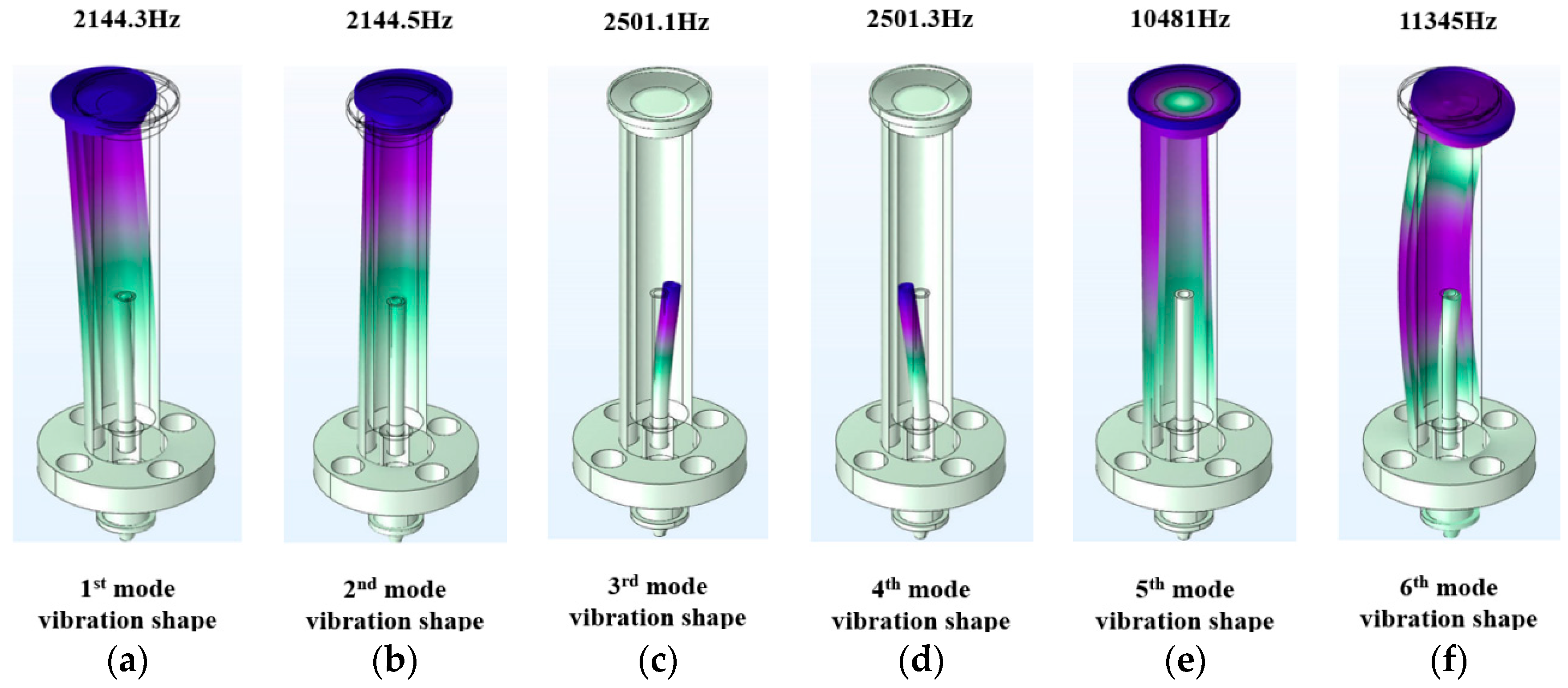
  • A finite element simulation model based on the PCT was established, and the theoretical analysis and simulation calculations were carried out to obtain the maximum chapter radius (R) of 20.09 μm, the minimum nutation accuracy (η) of 0.145 μm, and the maximum operating bandwidth (F) of 20 kHz for the fiber optic nutator. The 1st–6th order intrinsic frequencies of the mechanism were 2144.3, 2144.5, 2501.1, 2501.3, 10,481.0, and 11,345.0 Hz.
  • PCT deflection angle measurement experiments based on a parallel light collimator at different steady-state voltages were designed, and the results were compared with the PCT deflection angle obtained by simulation under the same boundary conditions. The relative error between the final simulation and experimental results was <5%, which proved the accuracy of the PCT simulation model.
  • A design for the relay optical path of the APT system with energy feedback compensation through the PCT-based fiber optic nutator was proposed, and the design parameters of the nutator based on the relay optical path of the APT system were calculated. Through comparison, all the structural parameters of the PCT-based fiber optic mechanism designed in this study met the requirements of the design parameters.
In summary, the scanning range, tracking accuracy, and tracking bandwidth of the PCT-based fiber optic nutator can be close to or even higher than the relevant parameters of traditional fine tracking systems. This structurally realizes the lightweight replacement of the fiber coupling components of the traditional APT system. This study can guide interplanetary laser communication integration. The mechanism provides key device support for the next SMF coupling control experiments based on the fiber optic nutation, and the PCT simulation model and theory proposed for the mechanism lay the foundation for the subsequent fiber optic transient nutating movement analysis. Owing to the author’s scientific background, the control circuit and nutation algorithm of the PCT-based fiber-optic nutator are not thoroughly studied and discussed in this paper. In the future, we will build an APT system with complete optical and electronic circuits and nutation control algorithms based on collaborations with colleagues in related fields. Experimental and simulation analyses on the light coupling efficiency of the fiber-optic nutator will also be pursued.

Author Contributions

Conceptualization, B.P. and P.R.; Methodology, B.P., P.R., J.H. and Z.C.; Software, B.P. and X.W.; Formal analysis, B.P.; Investigation, B.P., X.L. and Z.C.; Resources, P.R., J.H., X.L. and Y.W.; Writing—original draft preparation, B.P.; Writing—review and editing, B.P. and P.R.; Supervision, P.R.; Project administration, B.P. and P.R.; Funding acquisition, P.R. and J.H. All authors have read and agreed to the published version of the manuscript.

Funding

This research was funded by the National Key Research and Development Program of China, grant number 2022YFC2203801.

Institutional Review Board Statement

Not applicable.

Informed Consent Statement

Not applicable.

Data Availability Statement

Data underlying the results presented in this paper are not publicly available at this time, but may be obtained from the authors upon reasonable request.

Conflicts of Interest

The authors declare no conflict of interest.

References

  1. Yamac, D.; Frederic, M.D. Fiber-coupling efficiency for free-space optical communication through atmospheric turbulence. Appl. Opt. 2005, 44, 4946–4952. [Google Scholar]
  2. Fidler, F.K.; Knapek, M.; Horwath, J.; Leeb, W.R. Optical communications for high-altitude platforms. IEEE J. Sel. Top. Quantum Electron. 2010, 16, 1058–1070. [Google Scholar] [CrossRef]
  3. Arnon, S.; Rotman, R.; Kopeika, N.S. The performance limitations of free space optical communication satellite networks due to vibrations-analog case. Opt. Eng. 1997, 36, 3148–3157. [Google Scholar] [CrossRef]
  4. Hu, D.J.J.; Liu, L.; Dong, H.; Zhang, H. Design of a broadband fiber optic mode coupler for multimode optical coherence tomography. Photonics 2023, 10, 162. [Google Scholar] [CrossRef]
  5. Song, W.; Xie, Y.; Hao, W.; Han, J.; Yan, P.; Li, X.; Wang, Y.; Li, X.; Sun, C.; Li, Z. Spatial coupling efficiency of collimators based on gradient-index lens with an angle polish. Opt. Laser Technol. 2023, 162, 109245. [Google Scholar] [CrossRef]
  6. Wang, J.; Song, Y.; Jiang, H.; Dong, K.; Liu, Y. Prototype development of multi-target tracking system for space multi-node laser communication network. Optik 2023, 274, 170552. [Google Scholar] [CrossRef]
  7. Li, Z.; Liu, B.; Wang, H.; Chen, Z.; Zhang, Q.; Hua, K.; Yang, J. Target tracking and ranging based on single photon detection. Photonics 2021, 8, 278. [Google Scholar] [CrossRef]
  8. Zhang, F.; Han, J.; Ruan, P. Beam pointing analysis and a novel coarse pointing assembly design in space laser communication. Optik 2019, 189, 130–147. [Google Scholar] [CrossRef]
  9. Yu, S.; Wu, F.; Tan, L.; Ma, J. Static position errors correction on the satellite optical communication terminal. Opt. Eng. 2017, 56, 026112. [Google Scholar] [CrossRef]
  10. Heine, F.; Mühlnikel, G.; Zech, H.; Tröndle, D.; Seel, S.; Motzigemba, M.; Meyer, R.; Philipp-May, S.; Benzi, E. LCT for the European Data Relay System: In Orbit Commissioning of the Alphasat and Sentinel 1A LCTs. SPIE 2015, 9354, 133–138. [Google Scholar]
  11. Hu, S.; Yu, H.; Duan, Z.; Zhu, Y.; Cao, C.; Zhou, M.; Li, G.; Liu, H. Multi-parameter influenced acquisition model with an in-orbit jitter for inter-satellite laser communication of the LCES system. Opt. Express 2022, 30, 34362–34377. [Google Scholar] [CrossRef]
  12. Deng, K.; Wang, B.-Z.; Zhao, G.-H.; Huang, J.; Zhang, P.; Jiang, D.-G.; Yao, Z.-S. Principle and performance analysis of coherent tracking sensor based on local oscillator beam nutation. Opt. Express 2014, 22, 23528. [Google Scholar] [CrossRef] [PubMed]
  13. Geng, C.; Li, X.; Zhang, X.; Rao, C. Coherent beam combination of an optical array using adaptive fiber optics collimators. Opt. Commun. 2011, 284, 5531–5536. [Google Scholar] [CrossRef]
  14. Zhi, D.; Ma, Y.; Ma, P.; Si, L.; Wang, X.; Zhou, P. Adaptive fiber optics collimator based on flexible hinges. Appl. Opt. 2014, 53, 5434–5438. [Google Scholar] [CrossRef] [PubMed]
  15. Lachinova, S.L.; Vorontsov, M.A. Exotic laser beam engineering with coherent fiber-array systems. J. Opt. 2013, 15, 105501. [Google Scholar] [CrossRef]
  16. Zhang, L.; Yu, X.; Zhao, B.; Wang, T.; Tong, S. Method for 10 Gbps near-ground quasi-static free-space laser transmission by nutation mutual coupling. Opt. Express 2022, 30, 33465–33478. [Google Scholar] [CrossRef] [PubMed]
  17. Yan, X.; Cao, C.; Zhang, W.; Zeng, X.; Feng, Z.; Wu, Z.; Wang, T. Wavefront detection and compensation technology based on signal light nutation under atmospheric turbulence. IEEE Commun. Lett. 2021, 25, 3340–3344. [Google Scholar] [CrossRef]
  18. Swanson, E.A.; Bondurant, R.S. A Space-Based Optical Communication System Utilizing Fiber Optics; Technical Report; MIT Lincoln Laboratory: Lexington, MA, USA, 1989. [Google Scholar]
  19. Swanson, E.A.; Bondurant, R.S. Using fiber optics to simplify free-space lasercom systems. SPIE 1990, 1218, 70–82. [Google Scholar]
  20. Knibbe, T.E.; Swanson, E.A.; Roberge, J.K. Spatial tracking using an electro-optic nutator and a single-mode optical fiber. SPIE 1992, 1635, 309–317. [Google Scholar]
  21. Knibbe, T.E. Spatial Tracking Using an Electro-Optic Nutator and a Single-Mode Optical Fiber. Master’s Dissertation, Massachusetts Institute of Technology, Cambridge, MA, USA, 1993. [Google Scholar]
  22. Geng, C.; Luo, W.; Tan, Y.; Liu, H.; Mu, J.; Li, X. Experimental Demonstration of Using Divergence Cost-Function in SPGD Algorithm for Coherent Beam Combining with Tip/Tilt Control. Opt. Express 2013, 21, 25045. [Google Scholar] [CrossRef]
  23. Luo, W.; Geng, C.; Wu, Y.Y.; Tan, Y.; Luo, Q.; Liu, H.M.; Li, X.Y. Experimental demonstration of single-mode fiber coupling using adaptive fiber coupler. Chin. Phys. B 2014, 23, 014207. [Google Scholar] [CrossRef]
  24. Zhang, Q.M.; Wang, H.; Cross, L.E. Piezoelectric tubes and tubular composites for actuator and sensor applications. J. Mater. Sci. 1993, 28, 3962–3968. [Google Scholar] [CrossRef]
  25. Saito, Y.; Takao, H.; Tani, T.; Nonoyama, T.; Takatori, K.; Homma, T.; Nagaya, T.; Nakamura, M. Lead-free piezoceramics. Nature 2004, 432, 84–87. [Google Scholar] [CrossRef] [PubMed]
  26. Li, E.Q.; Xu, Q.; Sun, J.; Fuh, J.Y.H.; Wong, Y.S.; Thoroddsen, S.T. Design and fabrication of a PET/PTFE-based piezoelectric squeeze mode drop-on-demand inkjet printhead with interchangeable nozzle. Sens. Actuators A Phys. 2010, 163, 315–322. [Google Scholar] [CrossRef]
  27. Weibin, R.; Zhenguang, W.; Lining, S. Design and testing of one-dimensional nano-positioning stage with large travel range and high resolution. Nanotechnol. Precis. Eng. 2012, 10, 384–389. [Google Scholar]
  28. Fauzi, N.I.M.; Fen, Y.W.; Abdullah, J.; Kamarudin, M.A.; Omar, N.A.S.; Eddin, F.B.K.; Ramdzan, N.S.M.; Daniyal, W.M.E.M.M. Evaluation of structural and optical properties of graphene oxide-polyvinyl alcohol thin film and its potential for pesticide detection using an optical method. Photonics 2022, 9, 300. [Google Scholar] [CrossRef]
  29. Lee, C.M.; Engelbrecht, C.J.; Soper, T.D.; Helmchen, F.; Seibel, E.J. Scanning fiber endoscopy with highly flexible, 1 mm catheterscopes for wide-field, full-color imaging. J. Biophoton. 2010, 3, 385–407. [Google Scholar] [CrossRef] [Green Version]
  30. Pshenay-Severin, E.; Bae, H.; Reichwald, K.; Matz, G.; Bierlich, J.; Kobelke, J.; Lorenz, A.; Schwuchow, A.; Meyer-Zedler, T.; Schmitt, M.; et al. Multimodal nonlinear endomicroscopic imaging probe using a double-core double-clad fiber and focus-combining micro-optical concept. Light Sci. Appl. 2021, 10, 207. [Google Scholar] [CrossRef]
  31. Dreischer, T.; Maerki, A.; Weigel, T.; Baister, G.C.; Haupt, C.; Wehrle, K. Operating in sub-arc seconds: High-precision laser terminals for intersatellite communications. SPIE 2002, 4902, 87–98. [Google Scholar]
  32. Zhao, X.; Hou, X.; Zhu, F.; Li, T.; Sun, J.; Zhu, R.; Gao, M.; Yang, Y.; Chen, W. Experimental verification of coherent tracking system based on fiber nutation. Opt. Express 2019, 27, 23996. [Google Scholar]
  33. Wang, Z.L.; Wu, W. Piezotronics and piezo-phototronics: Fundamentals and applications. Natl. Sci. Rev. 2013, 1, 29. [Google Scholar] [CrossRef] [Green Version]
  34. Shang, Y.; Jiao, Z.; Wang, S.; Wang, X. Dynamic robust compensation control to inherent high-frequency motion disturbance on the electro-hydraulic load simulator. Int. J. Comput. Appl. Technol. 2009, 36, 117. [Google Scholar] [CrossRef]
  35. Drossel, W.G.; Hensel, S.; Kranz, B.; Nestler, M.; Goeschel, A. Sheet metal forming of piezoceramic–metal-laminar structures—Simulation and experimental analysis. CIRP Ann.-Manuf. Technol. 2009, 58, 279–282. [Google Scholar] [CrossRef]
  36. Wang, S.L.; Cao, W.H.; Fan, Y.J. The performance analysis and research of a new type of piezoelectric ceramic tube drivers based on ANASYS. Mater. Rep. 2012, 26, 154–157. [Google Scholar]
  37. Yang, M.M.; Wang, Y.E.; Wei, S.M. Modeling and simulation of radial polarized piezo tube. Electron. Compon. Mater. 2018, 37, 23–27+44. [Google Scholar]
Figure 1. Deflection principle of piezoelectric ceramic tube (PCT) nutator.
Photonics 10 00769 g001
Figure 2. Principle diagram of (a) Gaussian beam to single-mode fiber coupling, (b) fiber nutation scanning based on PCT.
Photonics 10 00769 g002
Figure 3. Structural representation of PCT-based fiber optic nutator.
Photonics 10 00769 g003
Figure 4. Physical image of the PCT deflection angle measurement system.
Photonics 10 00769 g004
Figure 5. Deflection angle of the PCT at ±175 V pulse.
Photonics 10 00769 g005
Figure 6. Experimental and simulation results of the PCT deflection angle at different voltages based on (a) x axial, (b) y axial.
Photonics 10 00769 g006
Figure 7. First six mode vibration shapes and analysis of the corresponding intrinsic frequencies of the PCT-based fiber-optic nutator.
Photonics 10 00769 g007
Figure 8. Deformation displacement distribution of the (a) PCT at a regulated voltage of 250 V along the ±x-axis, (b) tube’s upper-end face at a regulated voltage of 250 V along the ±x-axis, (c) tube’s upper-end face at a regulated voltage of 250 V along the ±y-axis, and the (d) tube’s upper-end face at a transient voltage of 250 V.
Photonics 10 00769 g008
Figure 9. Close loop of a beacon-free APT system’s relay optical path based on (a) position feedback and (b) power feedback.
Photonics 10 00769 g009
Figure 10. Simulation results of APT system’s (a) course tracking accuracy and (b) fine tracking accuracy. (c) Amplitude–frequency response.
Photonics 10 00769 g010aPhotonics 10 00769 g010b
Table 1. Experimental device for the deflection angle measurement of the PCT.
DeviceTypeMain Parameters
PCTPI PT230.943.2 mm × 2.2 mm × 30 mm, PIC255
Deflection mirrorYZ-GFSJP-XFull band, 5 mm × 1.2 mm
Piezo amplifierTriAngle TA100-38Input range: −10–10 V, gain: 25 times
AutocollimatorPI E-413.30Resolution: 1″, sampling interval: 1 s
Input powerGW GPC-30600Input range: −10–10 V, resolution: 0.1 V
Table 2. Design parameters of the relay optical path of the APT system.
Parameter TypeSymbolValue
Signal wavelengthλ1556.15 nm
Mode-field radius of SMF ω04.0 μm
Focal length of fine tracking optical systemfj2615.7 mm
Focal length of communication receiving branch fb 38.13 mm
Entry pupil diameter of fine tracking branchD10 mm
Coarse tracking bandwidthFc10.01 Hz
Field angle of fine tracking branchαj0.8 mrad
Table 3. Actual parameters and required design parameters of fiber optic nutator.
Maximum Nutation
Radius R
Minimum Nutation
Accuracy η
Maximum Bandwidth
F
Required design parameters≥15.25 μm≤0.91 μm≥359.69 Hz
Actual design
parameters
20.15 μm0.145 μm20 kHz
Disclaimer/Publisher’s Note: The statements, opinions and data contained in all publications are solely those of the individual author(s) and contributor(s) and not of MDPI and/or the editor(s). MDPI and/or the editor(s) disclaim responsibility for any injury to people or property resulting from any ideas, methods, instructions or products referred to in the content.

