Article

Laser Ultrasonic Automatic Detection Method for Surface Microcracks on Metallic Cylinders

1
College of Mechanical and Vehicle Engineering, Taiyuan University of Technology, Taiyuan 030024, China
2
Engineering Research Center of Advanced Metal Composites Forming Technology and Equipment, Ministry of Education, Taiyuan University of Technology, Taiyuan 030024, China
3
National Key Laboratory of Metal Forming Technology and Heavy Equipment, Taiyuan University of Technology, Taiyuan 030024, China
4
State Grid Shanxi Electric Power Research Institute, Taiyuan 030001, China
5
Shandong Special Equipment Inspection Institute Group Co., Ltd., Jinan 250101, China
*
Author to whom correspondence should be addressed.
Photonics 2023, 10(7), 798; https://doi.org/10.3390/photonics10070798
Submission received: 7 April 2023 / Revised: 3 July 2023 / Accepted: 7 July 2023 / Published: 10 July 2023
(This article belongs to the Special Issue Optical Measurement Systems and Instruments)

Abstract

:
Metallic cylinders are widely used in various fields of industrial production, and the automatic detection of surface microcracks is of great significance to the subsequent grinding process. In this paper, laser-excited surface acoustic waves (SAW) are used to detect surface microcracks. Due to the dispersion of SAWs on the cylinder surface, the SAWs exhibit different polarities at different positions. In order to improve the consistency of signals and the accuracy of the modeling, the angle at which the polarity is completely reversed is selected as the detection point. A laser ultrasonic automatic detection system is established to obtain signals, and the B-scan image is drawn to determine the location of the microcrack. By comparing the time–frequency diagrams of the reflected SAWs and transmitted SAWs, the transmitted wave is chosen to establish the microcrack depth prediction model. In addition, according to the trajectory of the grinding wheel, a prediction model based on the absolute depth of the microcracks is established, and the influence of the orientation of the microcracks on the signal energy is considered. The method proposed in this paper can provide a reference for the rapid grinding of microcracks on the surface of metallic cylinders; it has the characteristics of visualization and high efficiency, and overcomes the shortcomings of the currently used eddy current testing that provides information on the depth of microcracks with difficulty.

1. Introduction

Metallic cylinders are one of the important products in the iron and steel industry. As a workpiece for rotary parts, they are widely used in many industrial fields [1]. The surface quality of metallic cylinders has an important influence on the machining process of the part. During the process of producing metallic cylinders, surface defects such as microcracks will inevitably appear on the surface due to the workpiece and equipment used [2]. These microcracks are prone to further expansion during plastic processing [3], resulting in scrapped parts. Therefore, the high-precision non-destructive detection of surface microcracks in metallic cylinders is of great significance to the subsequent grinding process [4].
Magnetic particle testing (MT) [5], penetrant testing (PT) [6], eddy-current testing (ECT) [7] and ultrasonic testing (UT) [8] are the commonly used non-destructive methods used to test for surface defects. MT is mainly applied to the surface detection of ferromagnetic materials, but it cannot be applied to the detection of copper, aluminum and other non-ferromagnetic materials [9]. PT is able to fully display the shape, size, position and depth of the defect by using the capillary principle of the imaging agent, but it can only be used for the detection of surface opening defects, and it easily produces chemical pollution [10]. Although ECT can be applied to the detection of defects in various metal and alloy conductive material specimens, it cannot reveal the nature and characteristics of the defects in the signal, and also cannot provide technical reference for subsequent grinding [11]. UT has the advantages of involving various detection methods and possessing a high detection efficiency, and is widely used in industrial automation detection [12]. Compared with piezoelectric ultrasonic testing, laser ultrasonic (LU) testing can realize the long-distance excitation and detection of ultrasonic waves, and has a higher temporal and spatial resolution; it is therefore a method that can achieve online ultrasonic testing [13,14,15,16].
Zeng et al. [17] established a physical model for the LU detection of the position and depth of surface defects in cylindrical pipes; the surface defect is identified by the changes in the reflection waves of the surface acoustic wave (SAW) and shear wave, and the relationship between the surface defect and the peak value of the reflection surface wave is pointed out. Shant et al. [18] explored the propagation law of SAW on the cylindrical surface from the perspective of phase velocity and group velocity. By deriving the propagation of SAW in different coordinate systems and combining it with experiments, the phase–dispersion relationship of SAW on cylindrical components is proven and a clear mathematical basis is given, which shows the sensitivity of the phase to detecting changes in the sample geometry. Hu et al. [19] analyzed the process of changing the phase velocity and group velocity during SAW propagation on the cylindrical surface from the perspective of the wave number, and verified the theoretical results via experiments. Zhao et al. [20] built a hybrid laser–EMAT system and used time-of-flight analysis to detect artificial surface defects; the results showed that the proposed method has a high detection accuracy. In fact, cracks are not always perpendicular to the sample surface. Li et al. [21] used a seven-feature parameter support vector machine (SVM) model to intelligently and quickly identify the depths and angles of oblique surface cracks. Zeng et al. [22] used the finite element method to investigate the relationship between the crack orientation and the LU spectrum. Li et al. [23] studied the different reflection and transmission capabilities of different components of SAWs at cracks, and analyzed the relationship between the depth of surface cracks and the critical wavelength of surface SAWs. The above studies prove the feasibility of using SAWs to detect surface microcracks in metallic cylinders. However, due to the phase shift and dispersion characteristics of SAWs in the process of propagating on curved surfaces, the high-precision characterization of angled microcracks on the surface of metallic cylinders is significant to the following grinding process.
In this paper, an automatic LU experimental platform for a metallic cylinder was established to detect surface microcracks. The ultrasonic signals of the surface microcracks with different depths were obtained via rotational scanning, and the B-scan images were drawn to visually determine the location of the microcracks. According to the characteristics of reflection SAWs and transmission SAWs, the most suitable depth calculation model and definition method for microcrack grinding are determined, and the robustness of the model with different microcrack orientations is discussed. The method proposed in this paper can provide a reference for the rapid grinding of metallic cylinder surface.

2. Materials and Methods

2.1. Methods

Laser-excited ultrasound is a process in which laser energy is converted into mechanical energy [24]. When a pulsed laser beam is incident on a solid surface, part of the laser energy is absorbed by the solid and converted into heat energy. The irradiated area produces a local rapid temperature rise, which leads to local rapid thermal expansion and thus ultrasound generation; this is the thermoelastic mechanism of laser ultrasonic [25]. The advantage of the thermoelastic mechanism is that the power of the pulse laser is small and is not enough to exceed the damage threshold of the material surface; it will therefore not cause damage to the irradiated area of the test sample so is suitable for non-destructive testing. SAWs are used to detect surface microcracks in metallic cylinders, as shown in Figure 1, where the red beam represents the pulsed laser that excites the ultrasound, and the green beam represents the continuous laser that detects the ultrasound.
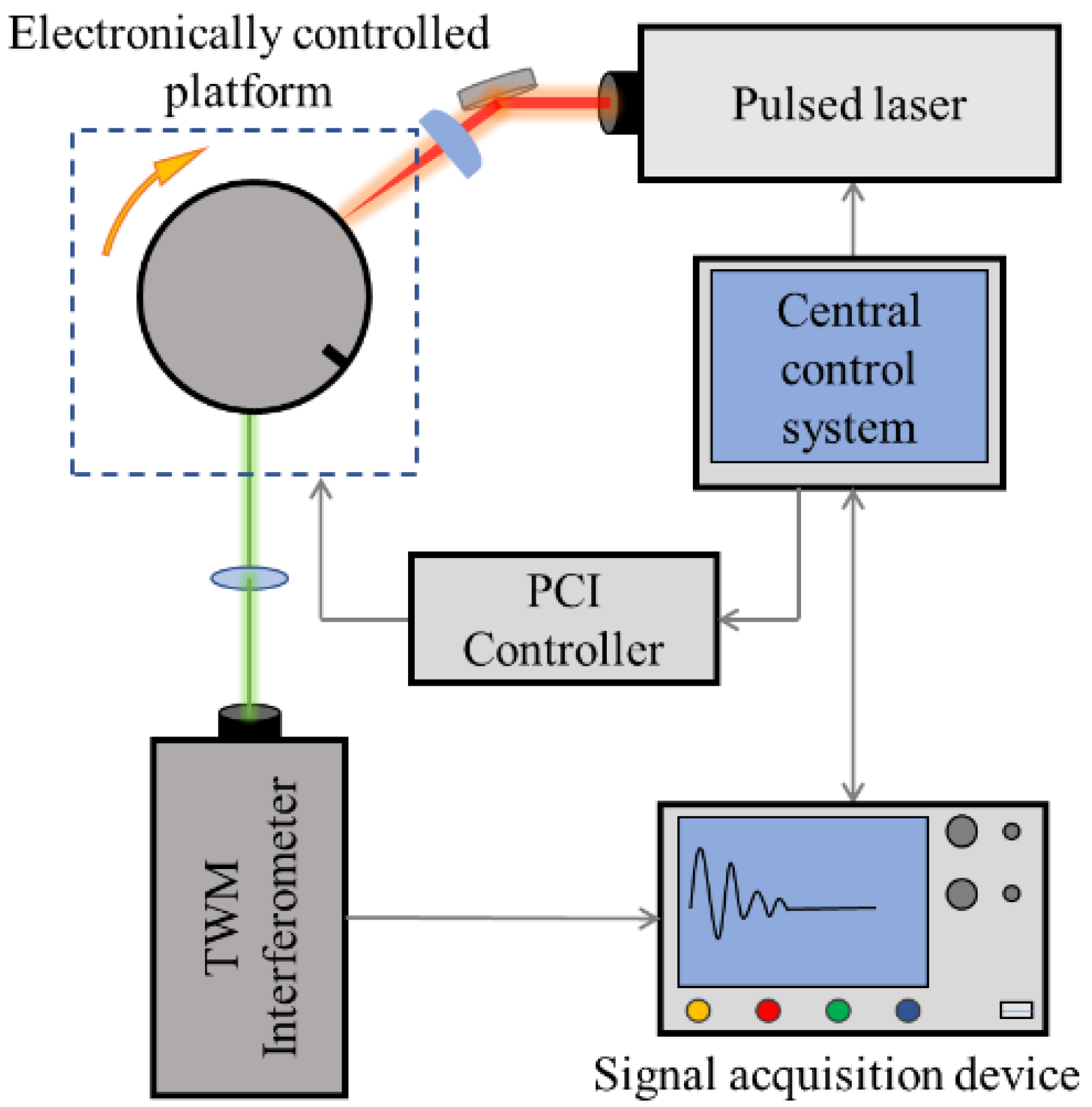
The LU testing system is shown in Figure 2. It was composed of a two-wave-mixing (TWM) interferometer, a pulsed laser, an electronically controlled platform, and a signal acquisition device, all of which were controlled by a control system.
The ultrasonic waves were generated by a Nd:YAG pulsed laser (Beamtech Nimma-400, Beijing, China) with a wavelength of 1064 nm and a pulse width of 8 ns; the main parameters are shown in Table 1. The pulsed laser was reflected by a reflector and then focused using a cylindrical lens (focal length 20 cm) into a 5 mm × 0.2 mm line-shape spot, and the applied energy was approximately 1 mJ.
The SAWs were detected using a TWM interferometer, which adopted a 532 nm single-longitudinal-mode continuous wave (CW) laser (Cobolt 05-01 Samba) as its source; the parameters of the CW laser are shown in Table 2. The Bi12SiO20 (BSO) crystal was the core of the TWM interferometer, which used its photorefractive effect to demodulate the ultrasonic vibration into a photoelectric signal to realize ultrasonic detection. Compared with other ultrasonic detection methods, the advantage of the TWM interferometer is that the reference beam is wavefront matched when it interferes with the signal beam, which ensures its applicability and signal-to-noise ratio (SNR) on rough surfaces [26,27], especially on the metallic cylinder. In addition, the two interfering beams can be kept orthogonal automatically without any additional active compensation equipment [28], so as to improve the stability of filtering out low-frequency interference. A plano-convex lens was placed in front of the TWM interferometer to collect cluttered reflected CW lasers from the rough surface.
In this experiment, the signal acquisition device consisted of a photodetector (PDA 10A2, 150 MHz) and an oscilloscope (Tektronix MBO34, 200 MHz, 2.5 GS/s). During the experiment, the waveform was averaged 128 times to reduce irrelevant noise in the data. The samples were fixed by a centering three-jaw chuck with a scale on the side. The stepper motor drove the chuck to rotate and was controlled by the computer via the PCI controller (PCI-1240U). The control program was developed using LabVIEW, and the stepping motor was controlled by outputting pulse signals to realize the stepping rotation of the sample.

2.2. Materials

Samples in this experiment were made of Q235 steel (the Q designates the yield point, and the 235 indicates the yield strength), and the chemical composition of Q235 is shown in Table 3. The diameter of the metallic cylinders was 10 mm, and the surface of all the samples was smooth and clean without scratches. The surface defects of the samples were replaced by artificial rectangular grooves, with a width of 0.2 mm and a depth of 0.2–1.0 mm, with an interval of 0.2 mm.
In the testing process, the sample was firstly installed in the chuck at a random position, and then the pulsed laser with a specified intensity was emitted from the Nd:YAG laser, and the laser beam was focused by a cylindrical lens with a focal length of 200 mm, forming a line source with a length of 5 mm and a width of 0.5 mm on the surface of the sample. Finally, SAWs propagating along the circumference of the metallic cylinder were excited. When the SAWs propagated to the detection point, the TWM interferometer demodulated the ultrasonic vibration into an electrical signal and transmitted it to the signal acquisition device (the signal was displayed on the oscilloscope and stored in the computer). Then, the LabVIEW program drove the stepper motor to rotate through the PCI controller, and the stepper motor drove the sample to rotate one step clockwise. The above steps were repeated until the metallic cylinder rotated a full circle.

3. Results and Analysis

3.1. Surface Wave Analysis

Assuming that the length of the focused line source along the axis of the cylinder is 2d (y direction shown in Figure 1a), and the SAW propagates along the sample surface, the displacement of the SAW can be expressed as follows [29]:
u ( α , t ) = A d d Q ( ω ) e i ω [ t s ( ω ) r α ] d ω
where α is the angle between the excitation and detection points, t represents the propagation time, A is the amplitude of the SAW, r represents the radius of the cylinder, and ω is the angular frequency. Q(ω) = 1/(1 + iωτ)2 represents the spectrum of a normalized function of the pulsed laser shape and τ is the width of the pulsed laser. S(ω) = 1/V(ω) is the SAW slowness and V(ω) represents the dispersion curve.
The polarity of a broadband SAW changes as it propagates along the cylindrical surface due to the dispersion. The dispersion curve V can be approximated as follows:
V = V R ( 1 + ε k a )
where ε is a constant related to the wave velocity, VR represents the velocity of the SAW, and ka is the wave number. For the phase lag of the SAW φ = φR + εα, it can be seen that φ is the sum of the phase lag φR due to the propagation at the constant velocity VR and an additional phase shift εα due to the dispersion in the high-frequency range.
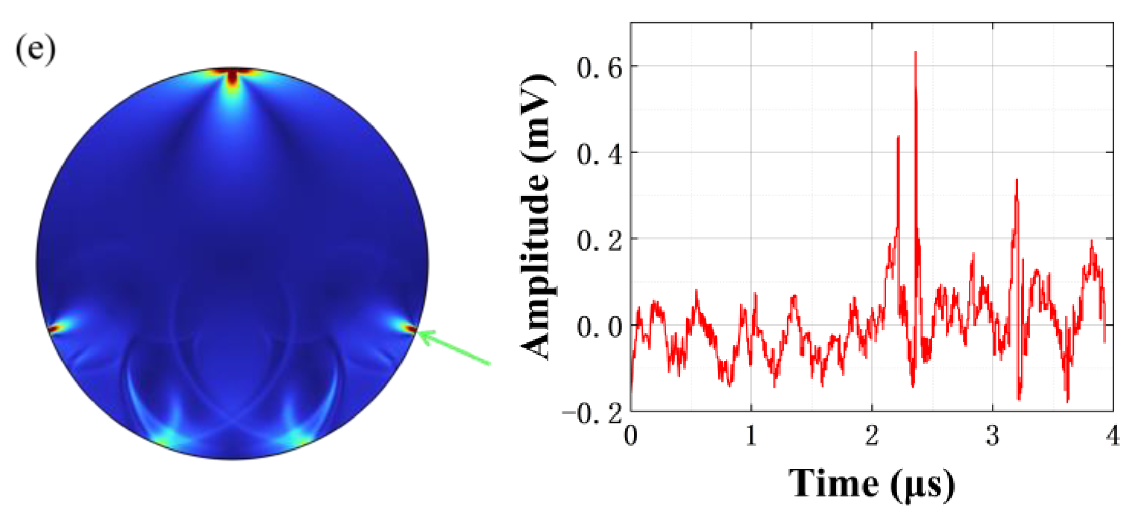
Figure 3 shows the LU field simulation images and the measured signals of the SAWs propagating along the metallic cylinder surface detected by the TWM interferometer. The software used for numerical simulation was COMSOL Multiphysics. Since the SAW propagates along the surface of the circle, a gradient grid is used to divide the circular area; the grid size near the outer circle is 1 μm, and the grid size near the center of the circle is 100 μm. The pulse width of the pulse laser is 8 ns, and the length of the thermoelastic region is 0.5 mm. The material is set to steel and the time step of the solution is 10 ns. In order to visually display the process of SAW polarity change, the top of the metallic cylinder is used as the starting point of 0°, and the detection point rotates clockwise to receive the SAW signal. The red signals in Figure 3a–e are the experimental signals of the receiving point at 30°, 50°, 70°, 90° and 110° from the excitation point, respectively, and the detection points of each signal are marked with green arrows in the simulated wavefield. It can be seen that, due to the phase lag, the polarity of the SAW will change when propagating on the surface of the metallic cylinder, and that the low-frequency part of the SAW will exceed the high-frequency part in the process of moving away from the excitation point.
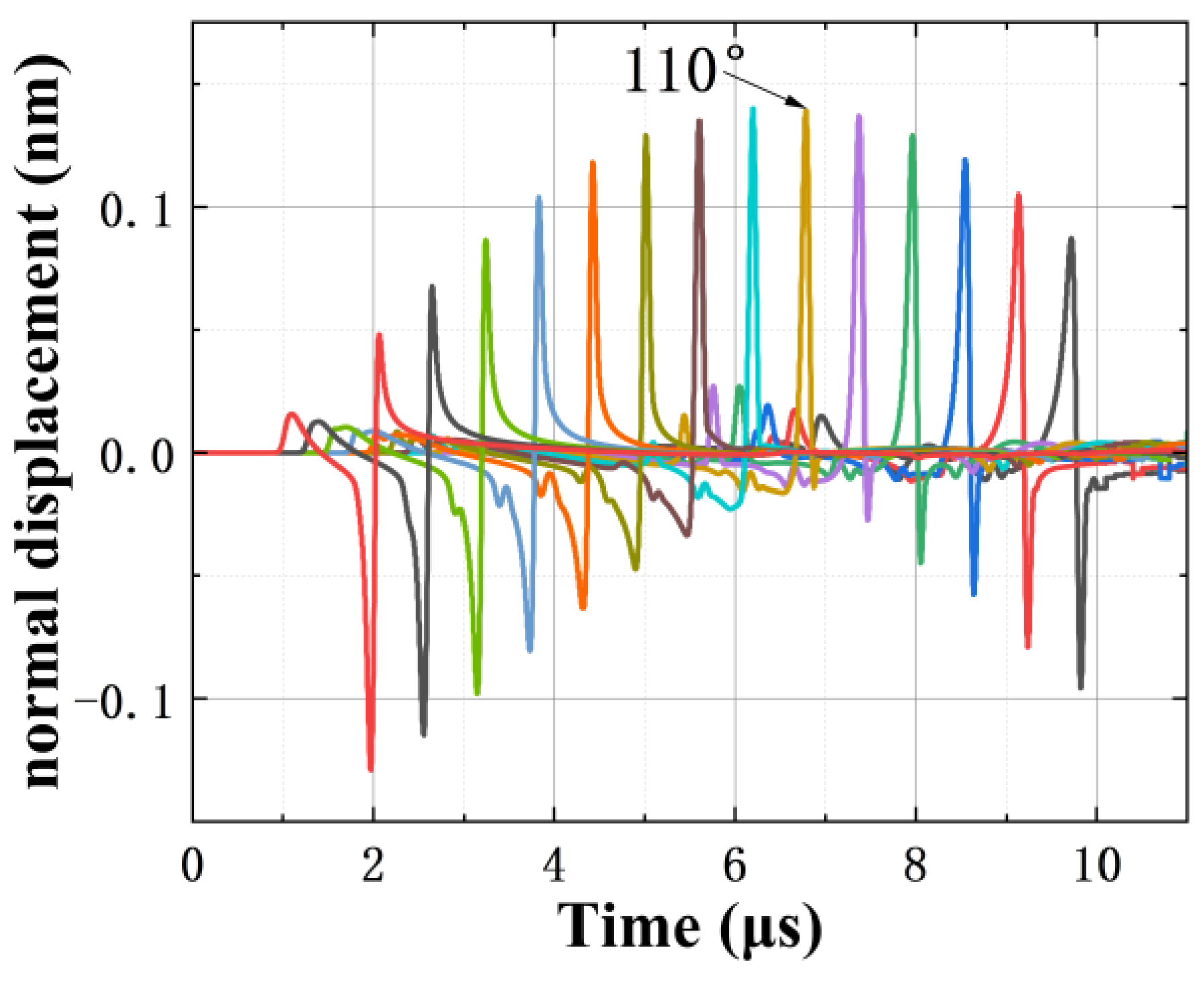
In order to show the process of SAW polarity change more intuitively, a collection of SAW waveforms with a detection point interval of 10° is drawn, as shown in Figure 4. It is not difficult to find that, as it gradually moves away from the excitation point, the polarity of the SAW changes periodically; it is gradually transformed from unipolar to bipolar, and then from bipolar to unipolar. At the position of 110° from the excitation point, the SAW is transformed into complete monopole waves [30].
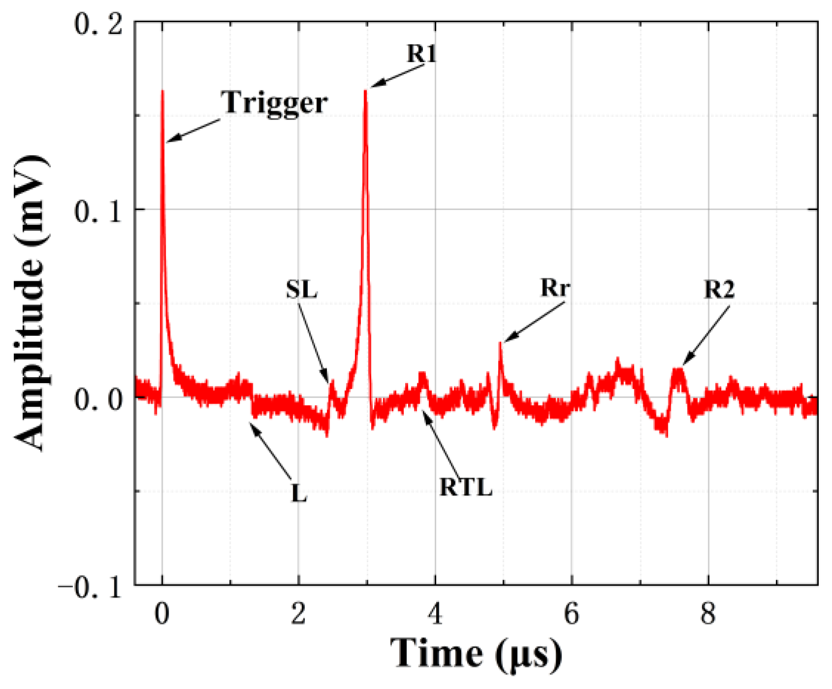
In the process of propagating along the circumference surface, the SAW encounters the microcrack and undergoes complex waveform transitions [31]. When the excitation point and microcrack are located on the opposite side of the detection point and α < 180°, the signal detected by the TWM interferometer is as shown in Figure 5. After pulsed laser excitation, the skimming longitudinal wave (SL) propagating along the surface of the cylinder first propagates to the detection point. After passing the detection point, the SL continues to propagate forwards clockwise, encounters the microcrack, reflects, and forms the skimming longitudinal wave reflection (SLr). After that, the SAW propagating clockwise (R1) passes through the detection point. When it propagates to the front of the defect, part of it is reflected and forms the defect reflected wave (Rr) [32]. The other part propagates along the microcrack to the bottom of the defect and forms the transformed longitudinal wave (RTL). The RTL propagates inside the cylinder to the detection point. Because the velocity of the RTL is greater than the Rr, the RTL appears before the Rr in Figure 5. The SAW propagating counterclockwise (R2) has a long travel distance and needs to pass through the microcrack, so the amplitude is significantly smaller than that of R1.

3.2. Identification of the Surface Microcrack’s Location

During the propagation of the SAW on the cylindrical surface, not only will dispersion occur [33], but complex converted waves will also be generated when the SAW interacts with microcracks; this makes it difficult to accurately determine the location and depth of the microcracks using the pulse-echo method. In this paper, the rotation scanning method is used to determine the location of microcracks. During the scanning process, the angle between the pulse laser and the detection point is fixed at 110°, and only the sample is rotated. Since the laser ultrasonic signal is unstable during the acquisition process, the requirement of unipolarity helps to improve the consistency of the acquired signal and improve the accuracy of the modeling. This method can not only reduce the cost of the experiment, but is also easy to operate and can effectively reduce unnecessary errors caused by adjusting the excitation and detection positions during the experiment.
Five samples with different microcrack depths D were detected, and the surface wave B-scan images are shown in Figure 6. The following information can be obtained via the B-scan images:
1. The yellow line at time 0 in each figure represents the trigger signal (the wave at time 0 in Figure 5), the notched yellow line at 3.2 μs represents R1, and the short yellow line that appears after the gap in the notched yellow line is R2. The times taken for R1 and R2 to travel from the excitation point to the detection point in the metallic cylinder (Φ = 10 mm) are about 3.2 μs and 7.4 μs, respectively. In the same signal, either R1 or R2 will always be affected by microcracks.
2. There are two microcrack reflected waves in the same image, and as the metallic cylinder rotates, the two reflected waves will gradually approach, overlap, and then gradually move away. This is because the line source will simultaneously generate SAWs propagating in two opposite directions. When the sample is rotated at a certain position, two opposite paths of excitation pointing to the microcrack detection point will have the same distance; it will appear that the two reflected waves arrive at the detection point simultaneously, that is, the two reflected waves overlap and cross in the displacement nephograms.
3. When the microcrack rotates between the excitation and detection points, R1 is blocked. The signals received before and after R1 is blocked are shown in Figure 7. Before being blocked, R1 and Rr can be observed from the waveform. After being blocked, the amplitude of R1 is significantly reduced, the Rr cannot be observed, and R2 appears at 7.4 μs (propagates counterclockwise). It should be noted that when the wavelength of the SAW is greater than the depth of the microcrack, even if blocking occurs, some low-frequency SAW can pass through the microcrack to reach the detection point. As shown in the notched yellow line in Figure 6a,b, when the depth of the microcrack is small, the transmitted SAW can still be observed at the notch. As the depth of the microcrack increases, the amplitude of the transmitted SAW becomes smaller and disappears gradually.
The surface microcrack is equivalent to a high-frequency filter. Some high-frequency components with shorter wavelengths in the SAW cannot pass through the microcrack and are reflected, while some low-frequency components with longer wavelengths can pass through the microcrack smoothly. Therefore, the ultrasonic signal received before being blocked is the entire R1 and the high-frequency reflected wave Rr. R2 has a long propagation distance and cannot pass through the defect, so it is hard to detect. With the rotation of the sample, the detection point and excitation point are on the opposite side of the defect, which causes the sudden change in the ultrasonic signal, as shown in Figure 7. The microcrack causes the high-frequency component of R1 to be blocked (the low-frequency SAW passing through the microcrack is the TR); therefore, the amplitude of R1 decreases obviously and the Rr disappears, and the amplitude of R2 increases sharply after R1 is blocked.
By using the B-scan image, the position of the microcrack can be easily determined. Since the positions of the detection point and excitation point do not change during the entire scanning process, the microcrack is located at the detection point when R1 is weakened and R2 is enhanced in the displacement nephograms. When R1 is enhanced and R2 is weakened, the microcrack is located at the excitation point.

3.3. Identification of the Surface Microcrack’s Depth

The wavelet transform can provide a “time–frequency” window that varies with the frequency; it can specifically analyze a certain local area of the signal, which is suitable for ultrasonic signals that are changing in both the time domain and frequency domain. In order to identify the depth of the microcrack, the wavelet transform is used to analyze the Rr or TR in the time–frequency domain [34]:
W ( a , b ) = 1 a x ( t ) ψ ( t b a ) d t
where a is the scale, which controls the expansion and contraction of the wavelet function, b is the translation amount, which controls the translation of the wavelet function, t represents time, W (a, b) is the inner product of the ultrasonic signal x(t) and the wavelet basis function Ψ, and Ψ is the mother wavelet, with that used in this paper being the Morlet wavelet:
ψ ( t ) = exp ( i ω 0 t ) exp ( t 2 2 )
where ω0 is the center frequency.
The location of the microcrack is measured. In order to obtain the Rr and TR, the microcrack is rotated clockwise and counterclockwise by 20° based on the detection point, respectively. Figure 8 shows the time–frequency analysis results of the Rr when D has values of 0.2 mm, 0.4 mm, 0.6 mm, 0.8 mm, and 1.0 mm, respectively (the orientation of the microcracks is along the radial). Since the center frequency of the SAW in this experiment is about 3 MHz, and the velocity of the SAW on the steel surface is about 3000 m/s, the wavelength of the SAW in this experiment is about 1 mm. When D is small (D = 0.2 mm), the high-frequency part of the SAW is blocked by the microcrack and reflected back to the detection point, which is Rr; its time–frequency analysis results are shown in Figure 8a. When D gradually increases, more low-frequency components of SAW will be reflected. From Figure 8b–e, it can be seen that the center frequency of the Rr gradually moves down.
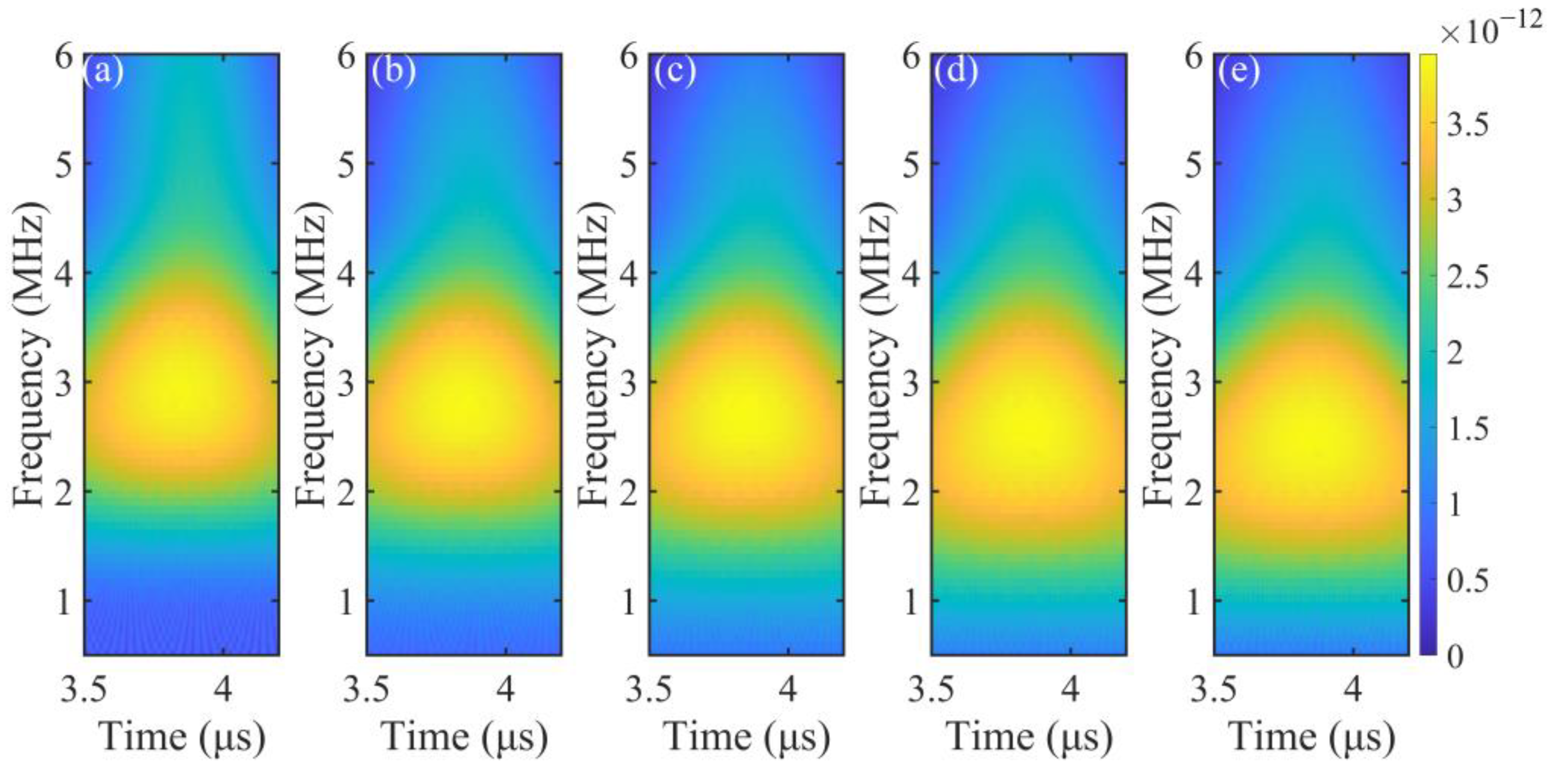
Figure 9 shows the time−frequency analysis results of the TR when the D values are 0.2 mm, 0.4 mm, 0.6 mm, 0.8 mm, and 1.0 mm, respectively. It can be seen that when D is small, only a small part of the SAW of the high-frequency components is blocked, and the center frequency of the TR is high. When D gradually increases, more and more high-frequency components of the SAW are blocked, so it can be seen from Figure 9 that the center frequency decreases with the increase in D, and only low-frequency components can pass through the microcrack. By comparing Figure 8 and Figure 9, it can be seen that when D changes, the change in the frequency range of the TR is more obvious than that of the Rr. This is because when the surface wave is reflected at the microcrack, there are not only reflected surface waves, but also waveform conversion. Due to the influence of the wave velocity, wavelength, and SNR ratio, it is difficult to distinguish these converted waves from reflected surface waves. For surface waves passing through the microcrack, since most converted waves propagate in the reflected direction, the transmitted waves are less affected by converted waves, so the TR is more sensitive to changes in D than the Rr [35]. According to this feature, the TR was selected for the characterization of the microcrack’s depth.
The purpose of this work is to provide a real-time reference for the rapid grinding of microcracks on the surface of a metallic cylinder. When the position and depth of the microcrack is determined, the surface of the metallic cylinder is ground with a grinding wheel controlled by a mechanical arm. In order to avoid edges and corners after grinding, the track of grinding is usually a curve composed of multiple curves [4], as shown by the dotted line in Figure 10a.
In fact, the orientation of microcracks on the metallic cylinder surface is diverse, so it is necessary to obtain the TR of microcracks with different orientations and depths by means of simulation in order to establish an accurate model. However, there are two methods used to define the depth of a microcrack. The first is the length of the microcrack itself, and the second is the radial distance from the end of the microcrack to the metallic cylinder surface (absolute depth), as shown in Figure 10b. In both methods, the orientation of the microcrack is defined as the angle between the direction of the microcrack and the x-axis; the angle is negative when the microcrack is on the left side of the x-axis, and the angle is positive when the microcrack is on the right side of the x-axis.
When the length of the microcrack is taken as D, the limit of the orientation angle is the angle at which the end of the microcrack intersects with the metallic cylinder surface. And when the absolute depth of the microcrack is taken as D, the limit of the orientation angle is the tangent line between the microcrack and the circle at the end of the microcrack. According to the geometric relationship of ΔTPO in Figure 10b, when D is at its largest, the orientation angle range of the microcracks is the smallest. In this experiment, the maximum depth of the microcracks is 1 mm, and the diameter of the metallic cylinder is 10 mm. Therefore, the range of β is less than 53°. Therefore, in order to compare the TR of the two depth models at different depths and orientation angles, the range of β was chosen to be from −50° to 50° (the smaller D, the larger the range of orientation angles that can be compared together).
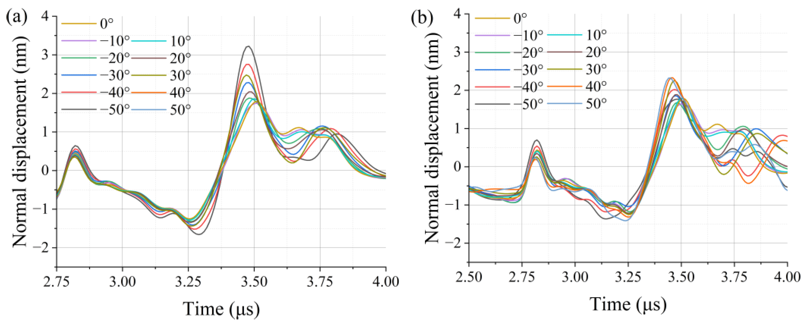
Figure 11 shows the simulation waveforms of the TR when D = 0.4 mm, as obtained via two depth definition methods. It can be seen from Figure 11a that when the microcrack length is constant and the orientation angle is changed, the amplitude of the TR changes obviously; meanwhile, in Figure 11b, although the length of the microcrack changes, the absolute depth remains constant, which results in a small variation in the amplitude of the TR. In fact, the microcrack can be regarded as a low-pass filter, and the high-frequency components in the SAW are reflected by the microcrack. Therefore, the absolute depth of the microcrack is the key to affecting the TR waveform, and different orientation angles will cause changes in the waveform conversion and propagation time.
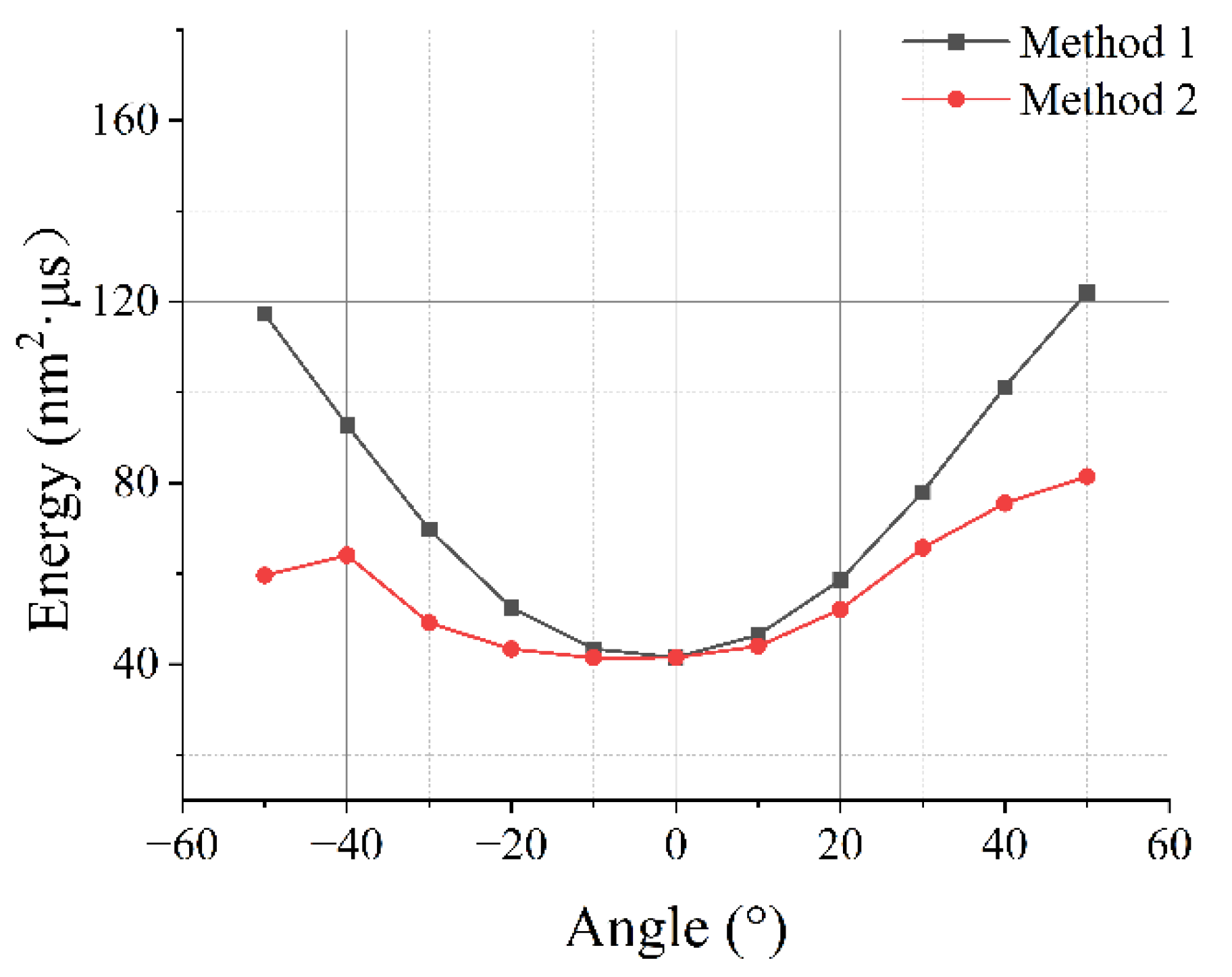
For the surface grinding of the metallic cylinder, since the trajectory of the grinding wheel is a smooth curve, instead of directly grinding the microcrack itself, the absolute depth of the microcrack is more suitable for the grinding process compared to the microcrack length. This can not only avoid the influence of orientation on the grinding accuracy as much as possible, but also provide a fast calculation method for microcracks and improve production efficiency. Since the SAW sees a waveform conversion at the microcrack, and the waveform of the TR is also affected by the orientation of the microcrack, the energy of the signal x(t) is used as the basis for calculating the absolute depth of the microcrack, as follows: E = t 1 t 2 [ x ( t ) ] 2 d t , where E is the signal energy, and t1~t2 is the time range of the TR. Figure 12 shows the energy of each TR in Figure 11. The black curve represents the energy of the TR when the microcrack length is constant, and the red curve represents the energy of the TR when the absolute depth of the microcrack is constant. It can be seen that the fluctuation in the black curve is obviously larger than that of the red curve, which proves that the prediction model established using the absolute depth has higher accuracy.
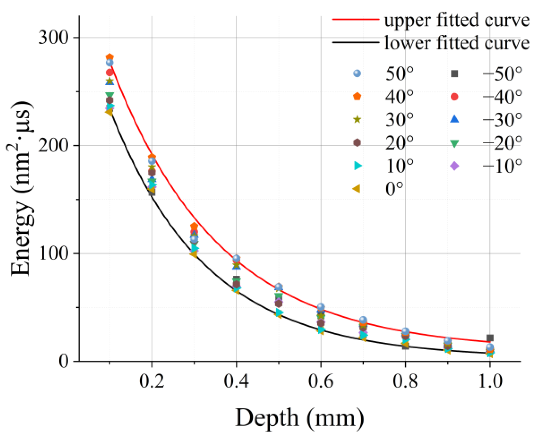
In order to establish a model that can rapidly predict the absolute depth of microcracks, the energy of the TR at absolute depths of 0.1 mm to 1.0 mm was calculated from the simulation signals when the orientation of the microcracks was −50° to 50°, as shown in Figure 13. It can be seen from Figure 13 that the smaller the absolute depth of the microcrack, the larger the deviation in the energy of the TR caused by the orientation is. But when the absolute depth is small, the energy of the TR is more sensitive to the change in the absolute depth. When the absolute depth of the microcrack is close to the wavelength of the SAW, the deviation in the energy of the TR caused by the orientation becomes smaller, and the energy of the TR becomes insensitive to the change in the absolute depth. When the microcrack is deep enough, the TR will disappear. The energy of the Rayleigh wave decays exponentially with depth [36]; therefore, the relationship between the energy E of the TR and the absolute depth D of the microcrack can be expressed as follows:
E = A exp ( D / B ) + C
where A, B, C are the fitting parameters. In Figure 13, the red curve is the fitting result of the maximum values of E at different depths using Equation (5), and the black curve is the fitting result of the minimum values of E at different depths. For the area between the red and black curves, the greater the energy of the TR, the smaller the range of D. In the region of higher energy, the deviation of D can be less than 0.1 mm. When the energy of the TR is small, affected by the orientation of the microcrack, the range of D is large, and the deviation can reach 0.3 mm or even higher. For the actual detected laser ultrasonic signal, affected by the signal-to-noise ratio, it is difficult to obtain a waveform similar to the simulation and extract accurate signal characteristic parameters [20]. Therefore, when grinding the microcrack, after obtaining the energy of the TR, the maximum value in the range of D is selected in order to plan the grinding trajectory to ensure that the microcrack is completely eliminated. Compared with the currently used ECT, LU can more easily provide the range in the microcrack’s depth, so it can assist the robot arm to achieve more accurate and rapid grinding trajectory planning.

4. Conclusions

In this paper, a method for the characterization of metallic cylinder surface microcracks based on laser ultrasonic is proposed. Since the laser-induced ultrasound is broadband, the polarity of the SAW will change due to the phase lag during the propagation of the cylindrical surface. The laser ultrasonic signal is unstable during the detection process, so the angle at which the polarity of the SAW is completely reversed is selected as the detection point in order improve the consistency of the detected signal and the accuracy of the modeling. A laser ultrasonic automatic detection system is established in order to obtain signals, and the B-scan image is drawn to determine the location of the microcrack.
In order to establish model that can characterize the depth of the microcrack, time–frequency analysis was used to investigate the changes in the reflection SAW (Rr) and transmission SAW (TR) at different microcrack depths. The results show that the TR is more sensitive to the change in the microcrack depth. To improve the robustness of the depth prediction model, the energy of the TR at different microcrack orientation angles was analyzed when the microcrack length or absolute depth was constant. When the depth is defined as the absolute depth of the microcrack, not only does the orientation of the microcrack have less influence on the energy of the TR, but it is also more suitable for the trajectory planning of the grinding wheel. Finally, in the established microcrack depth prediction model, the larger the TR, the smaller the depth range and the higher the prediction accuracy; the smaller the TR, the larger the depth prediction range. The upper limit of the depth range needs to be selected during the grinding process to ensure that the microcracks are completely eliminated. The method proposed in this paper can simultaneously perform positioning and quantitative analysis on the surface microcracks of metallic cylinders, and has the characteristics of visualization and a high detection efficiency, which is of great significance to the subsequent process of microcrack grinding during production.

Author Contributions

Y.Z. wrote the draft and edited the code of the program; Z.X. used the laser ultrasonic testing platform to obtain the photoacoustic signals, and sorted out the references; S.F. processed the data related to the experimental signal; H.Z. investigated the current development of laser ultrasonic and defect testing, and made engineering drawings and testing plans for samples; W.W. participated in the writing of some drafts and drew the schematic diagrams in the article; Y.L. funded the cost of the experiments and verified the feasibility of the experiment; B.Z. built the experimental platform and wrote the control program of the electronic control platform; W.S. modified the figures and carried out additional analyses. All authors have read and agreed to the published version of the manuscript.

Funding

This study was financially supported by the National Natural Science Foundation of China (Grant No. 52105557), the Natural Science Foundation of Shanxi Province (Grant No. 20210302124051) and the Key R&D Program of Shanxi Province (Grant No. SXKJ2022001) and the Central Government Guides the Special Fund Projects of Local Scientific and Technological Development (Grant No. YDZX20191400002149).

Informed Consent Statement

Informed consent was obtained from all subjects involved in the study.

Data Availability Statement

Data will be made available on request.

Conflicts of Interest

The authors declare no conflict of interest.

References

  1. Laber, K.; Dyja, H. The Effect of the Normalizing Rolling of S355J2G3 Steel Round Bars on the Selected Mechanical Properties of Finished Product. In Proceedings of the 5th International Conference on Mechatronic Systems and Materials, Vilnius, Lithuania, 22–25 October 2010; pp. 294–299. [Google Scholar]
  2. Yun, J.P.; Shin, W.C.; Koo, G.; Kim, M.S.; Lee, C.; Lee, S.J. Automated defect inspection system for metal surfaces based on deep learning and data augmentation. J. Manuf. Syst. 2020, 55, 317–324. [Google Scholar] [CrossRef]
  3. Fan, E.; Li, Y.; You, Y.; Lu, X. Effect of crystallographic orientation on crack growth behaviour of HSLA steel. Int. J. Miner. Metall. Mater. 2022, 29, 1532–1542. [Google Scholar] [CrossRef]
  4. Shi, W.; Zhang, J.; Li, L.; Li, Z.; Zhang, Y.; Xiong, X.; Wang, T.; Huang, Q. Analysis of Efficient and Fast Prediction Method for the Kinematics Solution of the Steel Bar Grinding Robot. Appl. Sci. 2023, 13, 1212. [Google Scholar] [CrossRef]
  5. Kasai, N.; Takada, A.; Fukuoka, K.; Aiyama, H.; Hashimoto, M. Quantitative investigation of a standard test shim for magnetic particle testing. NDT E Int. 2011, 44, 421–426. [Google Scholar] [CrossRef]
  6. Kudinov, I.I.; Golovkov, A.N.; Shishkin, P.A.; Skorobogatko, D.S.; Andreev, A.I.; Generalov, A.S. Evaluating the Efficiency of Using Ultraviolet Radiation Sources in Carrying Out Fluorescent penetrant Testing. Russ. J. Nondestruct. Test. 2022, 58, 57–69. [Google Scholar] [CrossRef]
  7. Chen, Y.; Feng, B.; Kang, Y.; Liu, B.; Wang, S.; Duan, Z. A Novel Thermography-Based Dry Magnetic Particle Testing Method. IEEE Trans. Instrum. Meas. 2022, 71, 9505309. [Google Scholar] [CrossRef]
  8. Chen, C.; Zhang, X. Research on laser ultrasonic surface defect identification based on a support vector machine. Sci. Prog. 2021, 104, 00368504211059038. [Google Scholar] [CrossRef]
  9. Lu, Z.; Zhang, Q.; Liu, X. New Magnetic Particle Cassette NDT Intelligent Detection Device. In Proceedings of the 2013 Fourth International Conference on Intelligent Systems Design and Engineering Applications, Zhangjiajie, China, 6–7 November 2013; pp. 403–406. [Google Scholar]
  10. Xu, G.; Guan, X.; Qiao, Y.; Gao, Y. Analysis and Innovation for Penetrant Testing for Airplane Parts. In Proceedings of the Asia-Pacific International Symposium on Aerospace Technology (APISAT), Shanghai, China, 24–26 September 2014; Chinese Society Aeronaut & Astronaut: Shanghai, China, 2014; pp. 1438–1442. [Google Scholar]
  11. Kiselev, E.K.; Gol’dshtein, A.E. Eddy-Current System for Testing Inner Diameter of Pipes. Russ. J. Nondestruct. Test. 2019, 55, 210–216. [Google Scholar] [CrossRef]
  12. Tian, Y.; Xu, G.; Wei, L.; Zhou, G.; Lin, Y.; Fan, Q.; Gu, X. Phased array ultrasonic S-scan testing of near-detection-surface defects based on a background subtraction algorithm. Mater. Res. Express 2022, 9, 036507. [Google Scholar] [CrossRef]
  13. Zeng, W.; Yao, Y. Numerical simulation of laser-generated ultrasonic waves for detection surface defect on a cylinder pipe. Optik 2020, 212, 164650. [Google Scholar] [CrossRef]
  14. Zhang, Y.; Wang, X.; Yang, Q.; Xue, R.; Zhang, J.; Sun, Y.; Xu, D.; Krishnaswamy, S. Research on epoxy resin curing monitoring using laser ultrasonic. Measurement 2020, 158, 107737. [Google Scholar] [CrossRef]
  15. Zhang, F.; Zhang, Y.; Wang, T.; Zhang, W.; Gong, P.; Yin, A. The effect of copper grain size on laser ultrasonic backscattered signal. Rev. Sci. Instrum. 2022, 93, 084901. [Google Scholar] [CrossRef] [PubMed]
  16. Qian, F.; Xing, G.; Yang, P.; Hu, P.; Zou, L.; Koukoulas, T. Laser-induced ultrasonic measurements for the detection and reconstruction of surface defects. Acta Acust. 2021, 5, 38. [Google Scholar] [CrossRef]
  17. Zeng, W.; Yao, F. Numerical simulation of laser-generated ultrasonic waves for identification of branched-breaking defects. Optik 2020, 208, 164435. [Google Scholar] [CrossRef]
  18. Kenderian, S. Phase and Dispersion of Cylindrical Surface Waves. Res. Nondestruct. Eval. 2010, 21, 224–240. [Google Scholar] [CrossRef]
  19. Hu, W.-X.; Qian, M.-L. Propagating Properties of Cylindrical Rayleigh Waves Generated by a Pulsed Laser Line Source. Chin. Phys. Lett. 2004, 21, 1294–1297. [Google Scholar] [CrossRef]
  20. Zhao, Y.; Sun, J.H.; Ma, J.; Liu, S.; Guo, R.; Song, J.F.; Jia, Z.Q. Application of the hybrid laser ultrasonic method in rail inspection. Insight 2014, 56, 360–366. [Google Scholar] [CrossRef]
  21. Li, H.Y.; Liu, Y.H.; Deng, J.; An, Z.W.; Pan, Q.H. Depth and Angle Evaluation of Oblique Surface Cracks Using a Support Vector Machine Based on Seven Parameters. Appl. Sci. 2022, 12, 8124. [Google Scholar] [CrossRef]
  22. Zeng, W.; Qi, S.K.; Liu, L.; Yao, Y.Y. Research on laser-generated Rayleigh waves with angled surface crack by finite element method. Optik 2019, 181, 57–62. [Google Scholar] [CrossRef]
  23. Li, H.; Pan, Q.; Zhang, X.; An, Z. An Approach to Size Sub-Wavelength Surface Crack Measurements Using Rayleigh Waves Based on Laser Ultrasounds. Sensors 2020, 20, 5077. [Google Scholar] [CrossRef]
  24. Yang, S.-J.; Kim, H.-S.; Jun, J.-H.; Chung, S.-C.; Park, J.-R. Changes in laser-induced thermoelastic effects depending on the position of an absorbing layer in indirect laser stimulation. J. Korean Phys. Soc. 2022, 80, 293–298. [Google Scholar] [CrossRef]
  25. Achenbach, J.D. Laser excitation of surface wave motion. J. Mech. Phys. Solids 2003, 51, 1885–1902. [Google Scholar] [CrossRef]
  26. Zhang, Y.; Wang, X.; Yang, Q.; Dong, F.; Du, X.; Yin, A. Characterization of mean grain size of interstitial-free steel based on laser ultrasonic. J. Mater. Sci. 2018, 53, 8510–8522. [Google Scholar] [CrossRef]
  27. Dong, F.; Wang, X.; Yang, Q.; Liu, H.; Xu, D.; Sun, Y.; Zhang, Y.; Xue, R.; Krishnaswamy, S. In-situ measurement of Ti-6Al-4V grain size distribution using laser-ultrasonic technique. Scr. Mater. 2018, 154, 40–44. [Google Scholar] [CrossRef]
  28. Stojkov, P.; Timotijevic, D.; Belic, M.R. Symmetries of two-wave mixing in photorefractive crystals. Opt. Lett. 1992, 17, 1406. [Google Scholar] [CrossRef]
  29. Clorennec, D.; Royer, D. Analysis of surface acoustic wave propagation on a cylinder using laser ultrasonics. Appl. Phys. Lett. 2003, 82, 4608–4610. [Google Scholar] [CrossRef]
  30. Liu, X.; Yang, S.; Liu, Y. Numerical Study for Surface-breaking Crack Detection on a Cylinder Using Laser-generated Ultrasound. In Proceedings of the 2018 15th International Conference on Ubiquitous Robots (UR), Honolulu, HI, USA, 26–30 June 2018; IEEE: Piscataway, NJ, USA, 2018; pp. 797–802. [Google Scholar]
  31. Clorennec, D.; Royer, D.; Walaszek, H. Nondestructive evaluation of cylindrical parts using laser ultrasonics. Ultrasonics 2002, 40, 783–789. [Google Scholar] [CrossRef]
  32. Arias, I.; Achenbach, J.D. In A model for the ultrasonic detection of surface-breaking cracks by the Scanning Laser-Source technique. In Proceedings of the Conference on Nondestructive Evaluation and Health Monitoring of Aerospace Materials and Composites III, San Diego, CA, USA, 16–17 March 2004; pp. 123–131. [Google Scholar]
  33. Pan, Y.; Rossignol, C.; Audoin, B. Acoustic Waves Generated by a Laser Line Pulse in Cylinders; Application to the Elastic Constants Measurement. J. Acoust. Soc. Am. 2004, 115, 1537–1545. [Google Scholar] [CrossRef]
  34. Guo, S.; Feng, H.; Feng, W.; Lv, G.; Chen, D.; Liu, Y.; Wu, X. Automatic Quantification of Subsurface Defects by Analyzing Laser Ultrasonic Signals Using Convolutional Neural Networks and Wavelet Transform. IEEE Trans. Ultrason. Ferroelectr. Freq. Control 2021, 68, 3216–3225. [Google Scholar] [CrossRef]
  35. Li, H.; Zhi, B.; Pan, Q.; An, Z.; Yu, R. Photoacoustic Detection Method for Depth of Surface Narrow Defects. Acta Opt. Sinica 2021, 42, 0212001. [Google Scholar]
  36. Chen, D.; Lv, G.; Guo, S.; Zuo, R.; Liu, Y.; Zhang, K.; Su, Z.; Feng, W. Subsurface Defect Detection Using Phase Evolution of Line Laser-Generated Rayleigh Waves. Opt. Laser Technol. 2020, 131, 106410. [Google Scholar] [CrossRef]
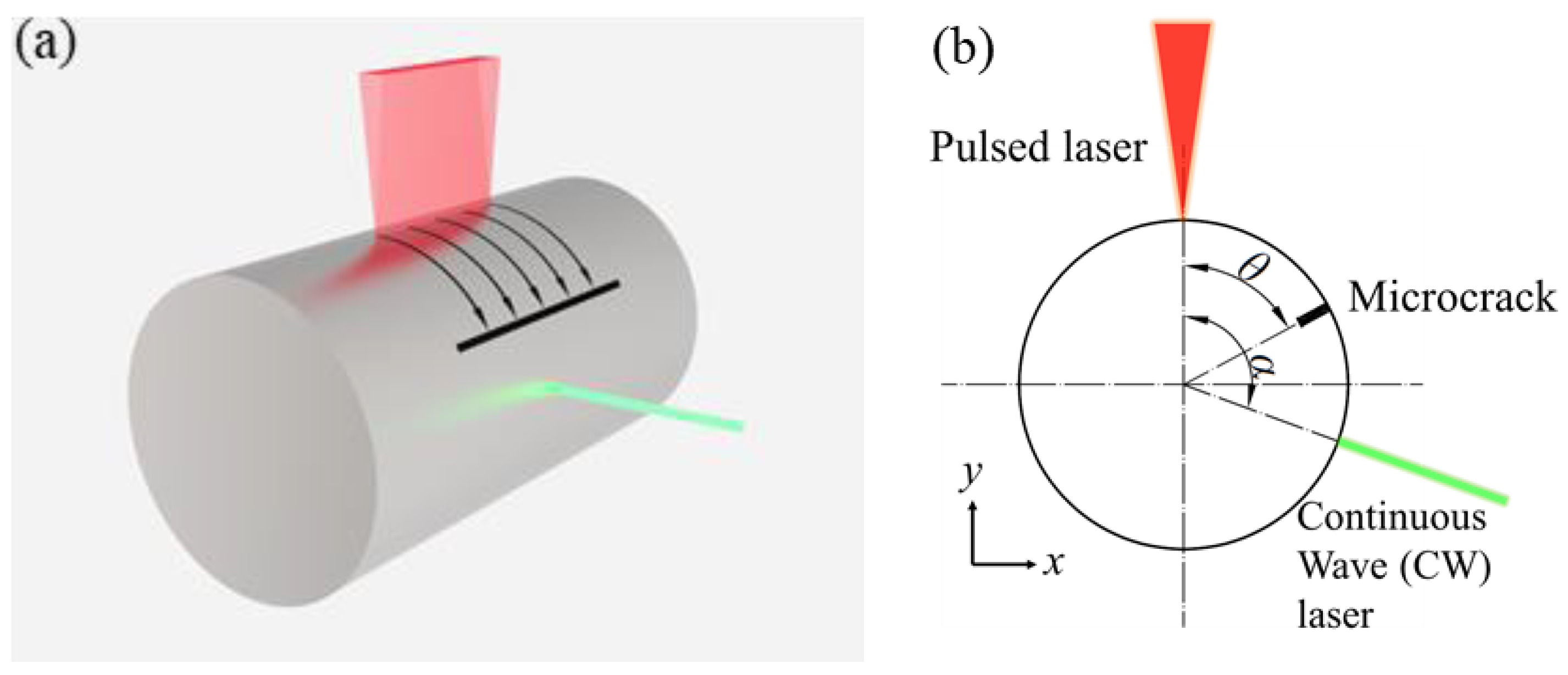
Figure 1. Schematic diagram of the relative positional relationship between pulsed laser, continuous laser and surface defects. (a) Three-dimensional schematic diagram of surface microcrack testing on the metallic cylinder using LU; (b) The geometric relationship between the excitation and detection beams, where θ is the angle between the microcrack and the excitation point, and α is the angle between the excitation point and the detection point.
Photonics 10 00798 g001
Figure 2. Laser ultrasonic testing system. The electronically controlled platform is driven by stepper motors, and the stepper motor is connected to the PCI controller.
Photonics 10 00798 g002
Figure 3. Schematic diagram of SAW propagating on a cylindrical surface and its waveform. The ultrasonic excitation point is on the top of the cylinder, and (ae) are the experimental signals of the detection point at 30°, 50°, 70°, 90° and 110° from the excitation point, respectively. The ultrasonic detection point is indicated by the green arrow in the figure. Changes in the polarity of the surface wave can be clearly observed.
Photonics 10 00798 g003aPhotonics 10 00798 g003b
Figure 4. SAWs collected at different detection points, from left to right. The angle α between the excitation point and the receiving point is from 30° to 160°, with an interval of 10°.
Photonics 10 00798 g004
Figure 5. Pulsed laser-excited ultrasonic signal. The peak at time 0 is the trigger signal. L represents the longitudinal wave, SL is the skimming longitudinal wave, R1 and R2 are the SAWs propagating clockwise and counterclockwise to the detection point, respectively, RTL is the longitudinal wave transformed from the SAW, and Rr represents the reflected SAW.
Photonics 10 00798 g005
Figure 6. Surface wave Bscan images of different microcrack depths D; the line at 3.2 μs is R1, and the line at 7.4 μs is R2. (a) D = 0.2 mm, (b) D = 0.4 mm, (c) D = 0.6 mm, (d) D = 0.8 mm, (e) D = 1.0 mm; the starting positions of all microcracks are random.
Photonics 10 00798 g006
Figure 7. Rayleigh wave received at the detection point before and after being blocked. The TR is the low-frequency SAW passing through the microcrack.
Photonics 10 00798 g007
Figure 8. Time-frequency analysis of the Rr. (a) D = 0.2 mm, (b) D = 0.4 mm, (c) D = 0.6 mm, (d) D = 0.8 mm, (e) D = 1.0 mm.
Photonics 10 00798 g008
Figure 9. Time-frequency analysis of the TR. (a) D = 0.2 mm, (b) D = 0.4 mm, (c) D = 0.6 mm, (d) D = 0.8 mm, (e) D = 1.0 mm.
Photonics 10 00798 g009
Figure 10. (a) Schematic diagram of metallic cylinder surface grinding. The short red line represents the microcrack, and the dotted line represents the track of the grinding wheel. (b) Depth defined in terms of the radial distance from the end of the microcrack to the surface of the metallic cylinder (absolute depth). The microcrack is rotated to the position 20° counterclockwise from the detection point, P represents the position of the microcrack, and T represents the point of tangency between the microcrack and the circle in which the end of the microcrack is located. The line connecting P and any point on T T has the same depth.
Photonics 10 00798 g010
Figure 11. (a) The simulation waveform of the TR when the length of the microcrack is 0.4 mm; (b) The simulation waveform of the TR when the absolute depth of the microcrack is 0.4 mm.
Photonics 10 00798 g011
Figure 12. Energy of each TR in Figure 11. The black curve represents the energy of the TR when the microcrack length is constant, and the red curve represents the energy of the TR when the absolute depth of the microcrack is constant.
Photonics 10 00798 g012
Figure 13. Fitting curve of the microcrack’s absolute depth and energy of the TR. For the red curve (R-square = 0.99398), the fitting parameters are A1 = 357.55, B1 = 0.23 and C1 = 3.14. For the black curve (R-square = 0.9972), the fitting parameters are A2 = 395.23, B2 = 0.26 and C2 = 9.84.
Photonics 10 00798 g013
Table 1. Pulsed laser parameters.
ParametersValues
Wavelength (nm)1064
Pulse width (ns)8
Pulse energy (mJ)200
Repetition frequency (Hz)1~10
Divergency angle (mrad)1
Beam diameter (mm)6
Table 2. TWM Interferometer parameters.
ParametersValues
Wavelength (nm)532
Power (W)2
Linewidth (nm)<10−5
Beam diameter (1/e2, mm)~1.5
Divergency angle (mrad)<1.5
Power fluctuation range (%)2
Spatial modeTEM00
Table 3. The chemical composition of Q235 steel.
C%Mn%Si%S%P%
0.221.40.350.050.045
Disclaimer/Publisher’s Note: The statements, opinions and data contained in all publications are solely those of the individual author(s) and contributor(s) and not of MDPI and/or the editor(s). MDPI and/or the editor(s) disclaim responsibility for any injury to people or property resulting from any ideas, methods, instructions or products referred to in the content.