Article

A Novel Reconfigurable Nonlinear Cascaded MZM Mixer, Amplitude Shift Key Modulator (ASK), Frequency Hopping and Phase Shifter

1
IoT and Signal Processing Research Group, ICT Research Institute, Faculty of Intelligent Systems Engineering and Data Science, Persian Gulf University, Bushehr 7516913817, Iran
2
Instituto de Telecomunicações, Universidade de Aveiro, 3810-193 Aveiro, Portugal
*
Author to whom correspondence should be addressed.
Photonics 2023, 10(8), 916; https://doi.org/10.3390/photonics10080916
Submission received: 10 July 2023 / Revised: 25 July 2023 / Accepted: 7 August 2023 / Published: 9 August 2023
(This article belongs to the Special Issue Optical Technologies Supporting 5G/6G Mobile Networks)

Abstract

:
A novel reconfigurable Microwave Photonics (MWP) mixer is presented in this paper, which can be configured to work as a frequency hopper, ASK modulator and phase shifter. This mixer is based on a cascaded Mach–Zehnder Modulator (MZM) structure. A general nonlinear analytical model for the structure is presented. This model is platform free, which means it can be applied to several MWP and integrated MWP platforms. Based on the analytical model, the performance of the structure and output results, such as the optical and electrical spectrum of the structure, are derived in mathematical closed-form expressions. The results of the presented analytical model are compared and evaluated with the results obtained from the simulation to prove the correctness of the analytical model. The presented structure has a simple form, which can be fabricated at a low cost. In addition, according to the obtained results from the analytical model, there is no need to change the arrangement of the structure to operate in any of the mentioned configurations, and the desired function is achievable only by changing the bias voltage of the modulators at the desired frequency.

1. Introduction

Microwave Photonics (MWP) science is an interdisciplinary science that combines Radio Frequency (RF) or microwave with optic fields. MWP, because of its advantages such as low noise, high bandwidth, photonic integration capability and immunity to electromagnetic waves interference, has been able to attract the attention of researchers in the fields of optics, telecommunications and electronics [1]. Extensive research has been conducted to explore the benefits of MWP, resulting in the emergence of numerous MWP applications. The applications of microwave photonics include analog-to-digital converters [2], microwave signal processing (for example, adjustable filters) [3,4], beamforming of phased array antennas [5], frequency converters [6], phase shifters [7], microwave waveform generators, microwave carriers [8,9], microwave imaging [10,11] and electro-optic oscillators [12,13].
Nonlinear Optical Materials (NLO) have been used in fabrication of lasers, photonics circuits and optical communication devices such as modulators and mixers. For example, Graphene has been used as an NLO material for a wide range of topics such as optical modulation [14], optical frequency mixing [15] and lasers [16]. As of today, some research has been performed on studying NLO materials and their applications specially in quantum communication [17,18]. For example, the problem of measuring an optical phase is particularly relevant in quantum communication, as is reported in [19]. However, the lack of a general model for describing nonlinear behavior of electro-optic devices in optical systems is felt, therefore one is presented in this paper.
A mixer is a three-port instrument that creates frequencies in such a way that the Radio Frequency (RF) and the Local Oscillator (LO) frequency are applied to mixer input ports, and, at the mixer output port, combinations of LO frequency and RF frequency are obtained. Until now, in microwave photonics, various types of mixers or frequency conversions have been reported [20,21,22,23,24,25,26]. A Dual Parallel Mach–Zehnder Modulator (DPMZM) mixer with high conversion efficiency was reported in [20]. A cascaded Mach–Zehnder Modulator (MZM) mixer, with low loss, was reported in [21]. A reconfigurable mixer, which is an arranged Dual Drive Mach–Zehnder Modulator (DDMZM) bias-free in parallel structure with a phase modulator, was reported in [22]. A Dual Drive Dual Parallel Mach–Zehnder Modulator (DD-DPMZM) mixer, with high conversion efficiency and the ability to avoid power fading, was reported in [23]. An MWP mixer with 0–2 π phase shift capability was reported in [24]. A reconfigurable MWP mixer based on Dual Polarization MZM (DPol-MZM) by changes in the detection part to achieve the IQ mixer, double balanced mixer, image reject and single-ended mixer was reported in [25]. A reconfigurable MWP mixer based on polarization division multiplexing DPMZM (PDM-DPMAZ) with the functionality of single-ended and double-balanced mixer by changing the detection structure and also due to the use of a phase shifter in structure, full phase shifting can be reached as reported in [26].
MWP mixers are not just used as frequency converters. They can also be used as devices for phase shifters, frequency doublers, beam forming, satellite repeaters, broadband microwave measurements, etc. [6,22]. As a device, it has the ability to do several tasks, it is more optimal to have one device that carries out several tasks instead of a separate device for each operation. By adjusting the modulator bias voltage or changes in the detection part of the mixer configuration, it can reach some functionality such as a phase shifter, frequency doubler, IQ, double balanced mixer, etc. Until now, various reconfigurable MWP mixers have been reported [22,24,25,26].
In this paper, we proposed a reconfigurable MWP mixer based on Cascaded MZM, which can be configured to work as a phase shifter, digital modulator and frequency hopper. The proposed structure model consists of two modulators that are connected in series. MZMs employed in this structure can be different, they can be a single-arm MZM or a dual-arm MZM. In the proposed structure, we employed single-arm MZMs in both stages. Thanks to the simplicity of the proposed structure, a novel simple digital ASK modulation in high frequencies can be achieved, which can be used in beyond 5G telecommunications. Additionally, phase tuning and frequency hopping can be mentioned as other functionalities of the proposed structure. In this structure, just by adjusting the bias voltage of one or both modulator(s), we can reach the mentioned functionalities easily. There is no further need to make changes to optical or detection parts.
The paper is organized as follows. In Section 2, analytical and close-form models for the proposed structure and also structure parameters are presented and investigated. In Section 3, various configuration results, comparisons and validations of the software simulation and analytical simulation that were carried out are presented. In Section 4, the work is summarized.

2. Analytical Model

In this section, the mathematical expression of the cascaded MZM mixer is theoretically investigated by considering the nonlinear behavior of the refractive index and its effects on the cascaded MZM mixer. Both MZMs are considered single-arm, and each MZM consists of just one Phase Modulator (PM).

2.1. PM Analytical Model

The PM is a waveguide surrounded by an electrode, which is illustrated in Figure 1. By applying an RF signal to the electrode, the signal is modulated on an optical carrier that enters the modulator from the laser source. If we assume that the optical signal entered into the modulator, its mathematical expression will be E i n = E 0 e j ω 0 t and RF signal voltage that is directly applied to the modulator is expressed as V g = V 0 + V R F c o s ( ω R F t + ϕ R F ) . Therefore, the output optical signal from the modulator can be expressed as Equation (1) [27].
E o u t = E 0 e x p ( j ω 0 t j ω 0 l m c Δ N r m ( V g ) )
where ω 0 , l m , c and Δ N r m , respectively, are the angular frequency of laser light, length of the modulator, light velocity and change of refractive index. Δ N r m is defined as the difference of refractive index at any voltage compared to zero voltage, and it can be computed by Equation (2).
Δ N r m ( V ) = N r m ( V ) N r m ( V = 0 )
The nonlinear refractive index can be modeled by a second-degree polynomial. This model can be expressed as Equation (3).
Δ N r m ( V ) = p 2 V 2 + p 1 V + p 0
The behavior of this model is illustrated in Figure 2. It clearly shows the nonlinear behavior of the refractive model. Table 1 shows the coefficients of the nonlinear model and linear approximation.
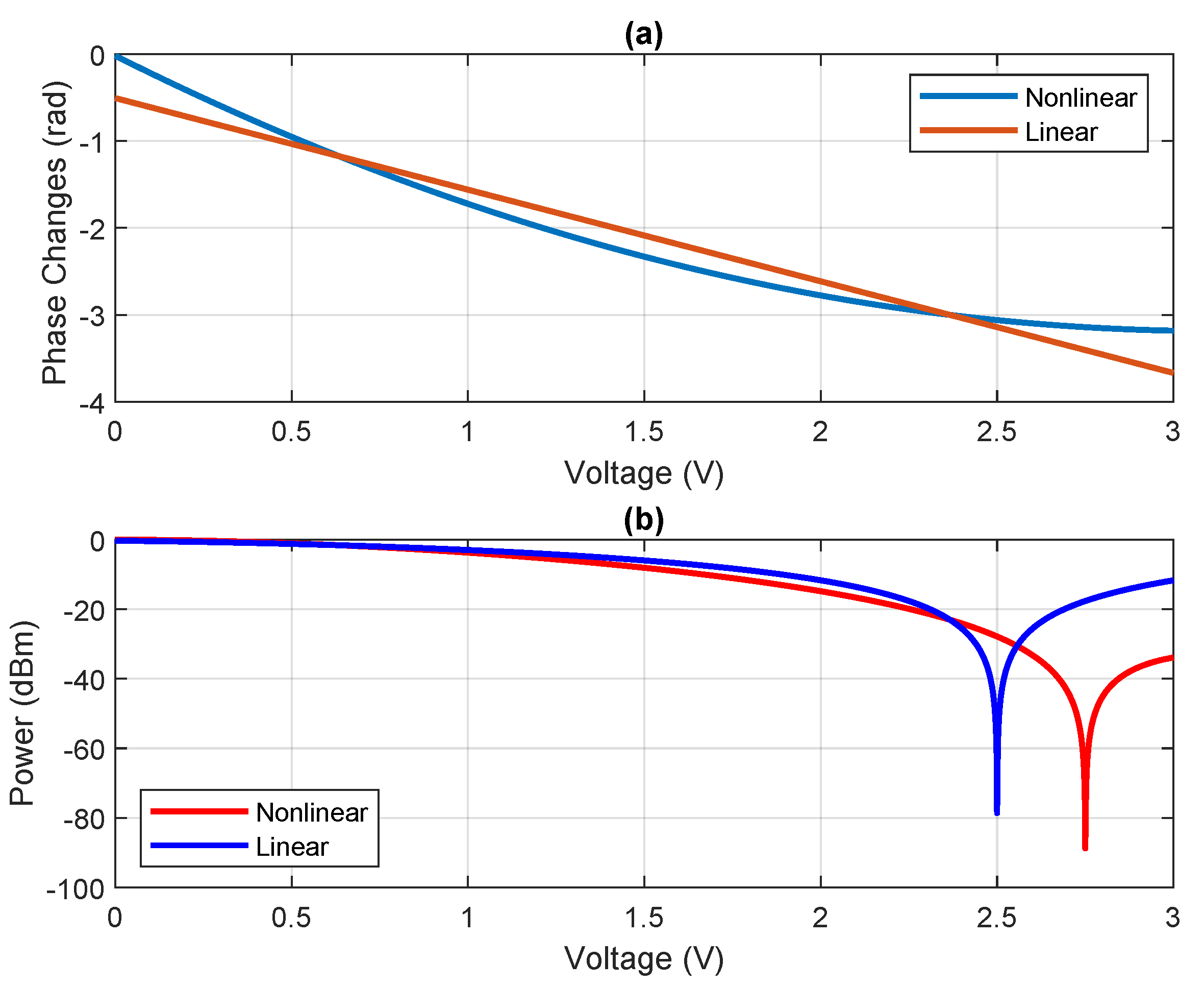
One of the important optical modulator parameters is V π . V π is defined as the amount of voltage that is created π radians of phase change between the input and output light of the modulator. This parameter is directly related to the refractive index of the modulator. Figure 3a, shows optical phase changes with respect to voltage changes. V π in our model, as shown in the Figure 3, occurs at 2.7 V in the nonlinear model and 2.5 V in the linear model, which have π radians phase difference. Figure 3b shows the optical signal power of the modulator. The reason for the power drop at the voltages of 2.5 and 2.7 V is because of the cancellation of two optical waves in the arms of MZM that occur at these voltages. In Figure 3a, the influence of the nonlinear behavior of the refractive index of the modulator on the phase of the optical wave is clearly visible. In the case where the linear approximation of the refractive index is used for the modulator, the phase decreases with a constant slope with respect to the voltage change. However, in the case where the nonlinear model of the refractive index is used, the phase changes with respect to the voltage are not with a constant slope and in an approximate way. It behaves as a parabola.
By replacing Equation (3) in Equation (1) and simplifying it, Equation (4) is obtained.
E o u t = E 0 e x p ( j ω 0 t ) e x p [ ( j β 0 ) l m ] × e x p [ ( ( j β 1 ) l m c o s ( ω r f t + ϕ r f ) ) ] × e x p [ ( ( j β 2 ) l m c o s ( 2 ω r f t + 2 ϕ r f ) ) ]
The new parameters can be calculated by Equation (5):
β 0 = ω 0 c [ p 0 + p 1 V 0 + p 2 V 0 2 + p 2 V r f 2 2 ] β 1 = ω 0 c [ p 1 V r f + 2 p 2 V 0 V r f ] β 2 = ω 0 c [ p 2 V r f 2 2 ]
It should be noted that if we use p 2 = 0 , the first-order model will be obtained.
The Fourier series of Equation (1) can be obtained by using the Jacobi–Anger expansion (6) [28].
e j z c o s ( α ) = n = n = + j n J n ( z ) e j n α
where J n ( z ) is a first-kind Bessel function of integer order n.
By using Jacobi–Anger expression (6) in Equation (4), the PM optical spectrum can be expressed as Equation (7) [29].
E o u t = E 0 e j ω 0 t e x p [ ( j β 0 ) l m ] × N = N = + ( j ) N J N ( β 1 l m ) e x p [ j N ( ω r f t + ϕ r f ) ] × N = N = + ( j ) N J N ( β 2 l m ) e x p [ j N ( 2 ω r f + 2 ϕ r f ) ]

2.2. MZM Analytical Model

As illustrated in Figure 4, each MZM consists of one PM. To drive the MZM analytical model, it needs to use the PM analytical expression that was achieved in Section 2.1. The MZM analytical general form can be reached by Equation (8).
E M Z M = 1 2 ( E i n + E P M )
where E P M = E i n × H P M , in this way, can express the PM transfer function ( H P M ) as Equation (9).
H P M = E P M E i n = e x p [ ( j β 0 ) l m ] × N = N = + ( j ) N J N ( β 1 l m ) e x p [ j N ( ω r f t + ϕ r f ) ] × N = N = + ( j ) N J N ( β 2 l m ) e x p [ j N ( 2 ω r f + 2 ϕ r f ) ]
By replacing Equation (7) in Equation (8) and employing Equation (9), we can reach a nonlinear model for MZM. This is achieved by Equation (10).
E = E i n 2 ( 1 + H P M )
To derive the transfer function for MZM, we can use the same method as described for PM. Therefore, the MZM transfer function can be expressed as Equation (11).
H M Z M = 1 2 ( 1 + H P M )

2.3. Cascaded MZM Mixer Model

In the proposed structure, the cascaded MZM mixer consists of two MZMs in series, as shown in Figure 4. The general form for this structure is achieved by Equation (12).
E o u t = E i n × H M Z M 1 × H M Z M 2
Therefore, by replacing Equation (11) in Equation (12), the nonlinear model for the cascaded MZM is achieved and can be expressed as Equation (13).
E o u t = E i n 4 × [ H P M 1 H P M 2 + H P M 1 + H P M 2 + 1 ]
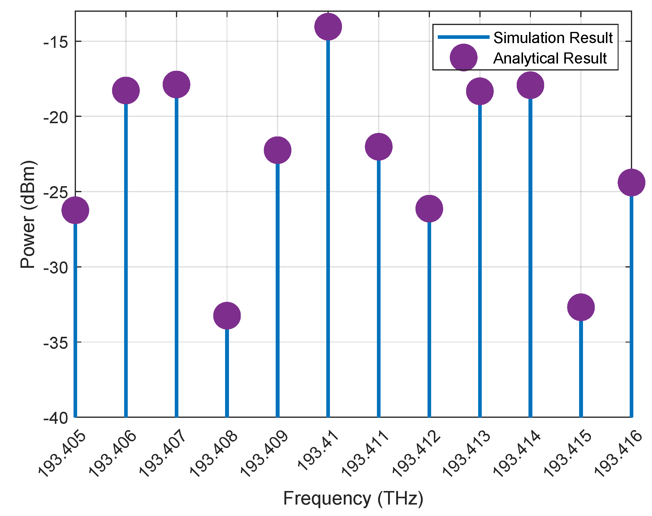
The optical spectrum of the mixer is illustrated in Figure 5, which is achieved by using Equation (13) and a simulation of the proposed structure in Lumerical. In the simulation and the analytical, both modulators are biased in quadrature points. Laser, RF and LO frequencies, respectively, are set at 193.41 THz, 3 GHz and 4 GHz. Additionally, laser power is set at 0 dBm. As can be seen from the figure, the simulation results are in very good agreement with the analytical output, which indicates the accuracy of the analytical expression.
In Figure 6, the results of the linear and nonlinear mixer are also compared. As it is clear, if we do not consider the effect of the nonlinear behavior of the modulator and only implement the modulator and mixer based on the linear model, we will have some errors in the optical spectrum.

2.4. Photo Diode Current and Frequency Combination

So far, the optical behavior of the cascaded mixer has been described. In general, the frequency mixing part requires nonlinear components. The mixing operation can be done by a nonlinear optical-to-electrical transformer device such as a photodiode. One of the advantages of photodiodes is a highly nonlinear behavior, and another advantage of photodiodes is the simplicity of this component. Therefore, considering these advantages of photodiodes, this make it suitable for employing in mixer structures. Therefore, this component is one of the most typical devices in microwave photonics, as it converts the optical signal to an electrical signal at the same time as it mixes the frequency.
The following Equation (14) shows the relation between photodiode current and optical signal of the mixer [27,30].
I p d = R P
where R is photodiode responsivity and P is the power of the optical signal applied to a photodiode, which can express power as Equation (15).
P E o u t E o u t *
note that * is conjugate operation.
By replacing Equation (15) in Equation (14), the photodiode current can be rewritten as Equation (16).
I p d R E o u t E o u t *
To obtain the photodiode current in the cascaded single-arm MZM configuration, we just need to replace Equation (13) in Equation (16).
Photodiode current in the proposed structure of the cascaded single-arm MZM configuration can be expressed as Equation (17).
I o u t s = | E 0 | 2 16 [ H P M 1 H P M 2 + H P M 1 + H P M 2 + 1 ] × [ H P M 1 H P M 2 + H P M 1 + H P M 2 + 1 ] *
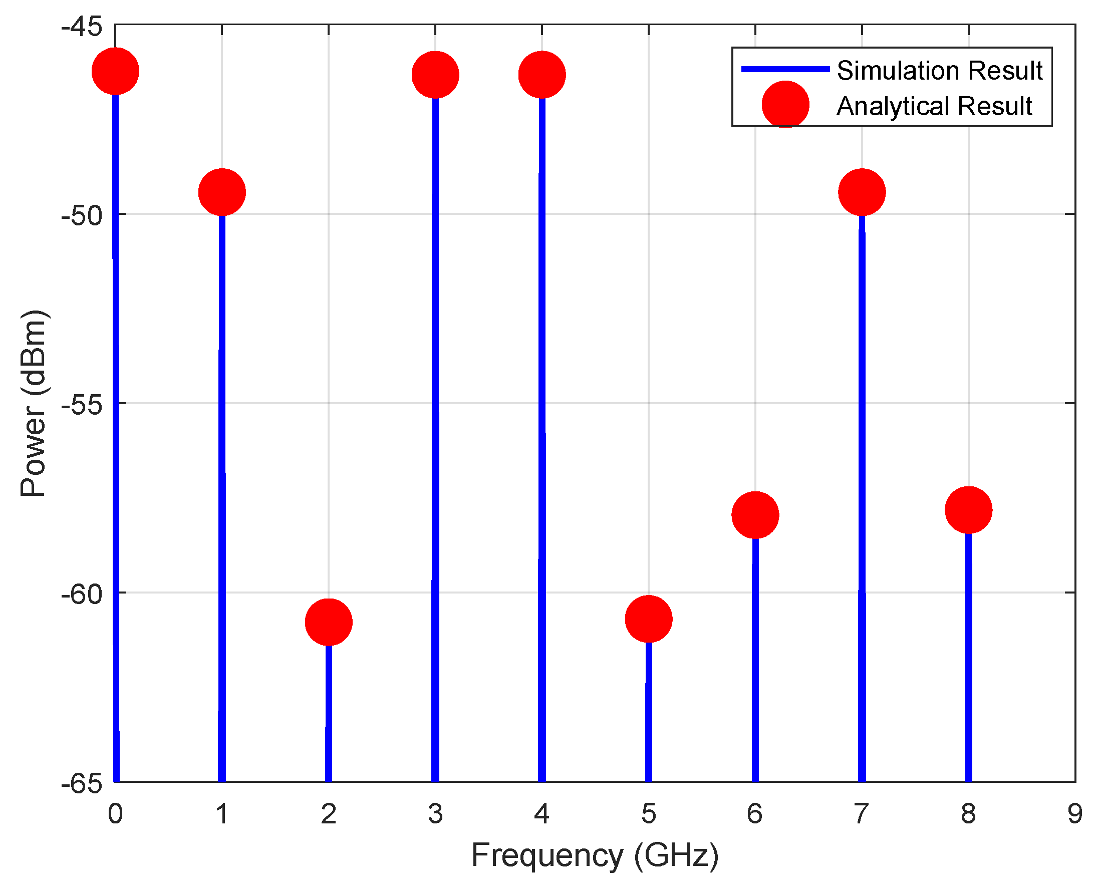
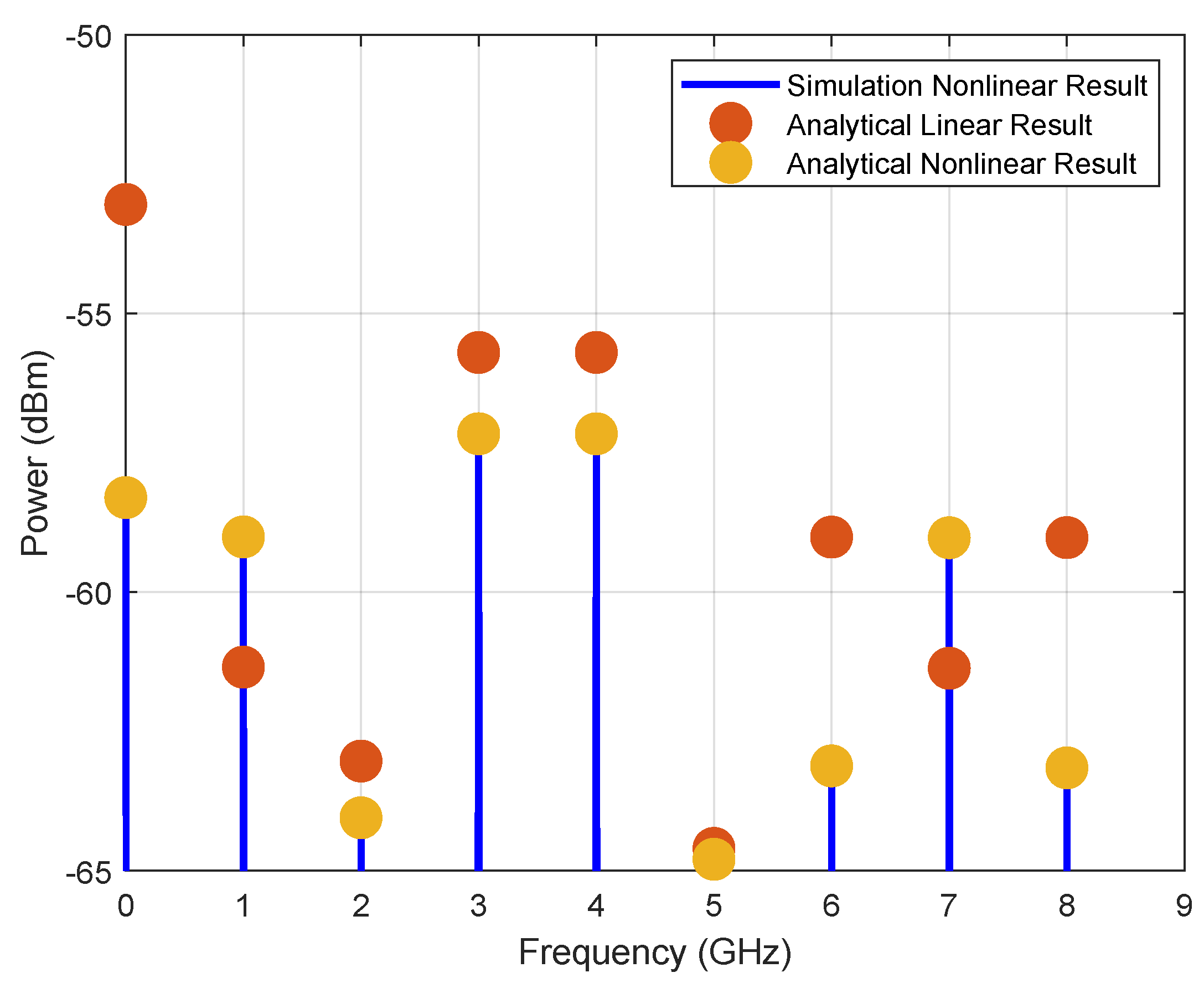
The electrical spectrum of the mixer is illustrated in Figure 7. The simulation results compared with analytical results completely match each other. The 1 and 7 GHz frequencies are down-conversion and up-conversion frequencies, respectively. A comparison of the linear mixer electrical spectrum and non-linear mixer electrical spectrum is shown in Figure 8. It is clear from the figure we have significant errors in some frequencies between the mixer with linear and non-linear models.

2.5. Conversion Loss

Conversion loss of the mixer is defined as the ratio of the output power at an Intermediate Frequency (IF) to RF applied power. This also can be expressed as Equation (18).
C L = S I F S R F
The Conversion Loss (CL) of the mixer is demonstrated in Figure 9. As expected, the mixer shows linear behavior at low voltages or small signal regimes, and, as the power of the IF signal increases, it goes above the small signal regime; hence, the mixer shows more nonlinear behavior. According to the behavior of the CL, it follows a constant value up to 25 dBm RF power; after 25 dBm, it suddenly and nonlinearly follows a new path, which determines the voltage of the signal in the large signal regime, and the mixer does not follow linear approximation behavior. It is worth mentioning that, by considering Equation (17), we come to the conclusion that the CL is directly related to the mixer optical input power. Therefore, the mixer conversion loss can be improved by increasing the entrance mixer’s optical power.

3. Various Configurations

In Section 2, the analytical model’s proposed structure was expressed and the analytical results were compared and evaluated with the simulation results. The results obtained from the simulation and analytical were well matched, which proves the correctness of the analytical expression for the nonlinear proposed structure. By using the analytical results, carried out functionalities, such as frequency hopping, amplitude shift key modulation and phase shifting, will be presented in the rest of this section.

3.1. Frequency Hopping

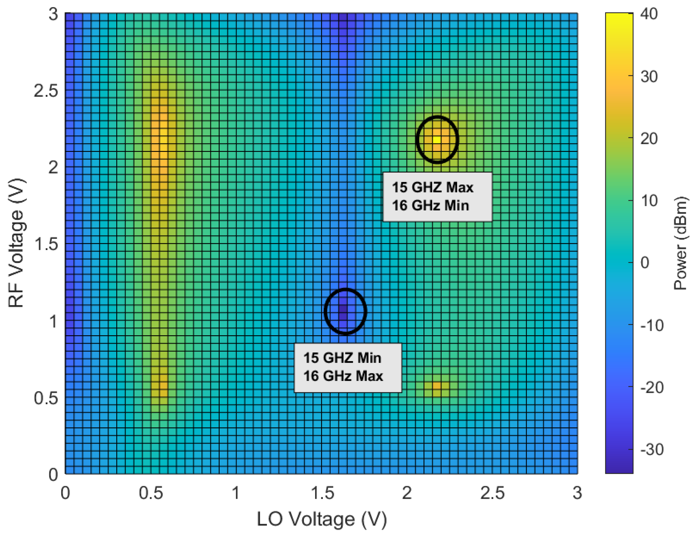
Frequency hopping is a wireless communication technology that sends the data using a special algorithm at the moment on a specific frequency. MWP frequency hopping is 10 3 to 10 6 times faster relative to electronic frequency hopping [31]. Moreover, MWP frequency hopping can be done at high frequencies due to no bandwidth limitation. For example, in this study, 15 and 16 GHz frequencies have been considered for research, and other frequencies can also be used.
In Figure 10, the electrical power level difference between 15 and 16 GHz frequencies by considering changes in bias voltage of MZM 1 and MZM 2 is shown. Where the RF signal modulates the optical carrier with MZM 1 and the LO signal modulates the optical carrier with MZM 2 . The simplicity of using the proposed structure for frequency hopping is the advantage of this structure because only by changing the bias voltage of mixer modulators one frequency can be easily suppressed compared to another frequency.
The areas specified in Figure 10 are laid out in such a way that for the switch from one frequency to another, if the bias voltage of the modulators has an error or is close to the voltage required for the frequency switch, the power level does not change suddenly and sharply. Assume at first that the system parameters set for 15 GHz frequency are maximum, where this parameter is MZM 1 bias voltage ( V b R F ) and MZM 2 bias voltage ( V b L O ), where V b R F and V b L O , considering Figure 10, are set at 2.15 volt for both of the bias voltages. Therefore, by setting the bias voltages of the structure to these voltages, the 15 GHz frequency is maximum and the 16 GHz frequency is suppressed. In a similar manner, for a switch from 15 to 16 GHz, it is just needed to adjust the bias voltage of the mixer, which, in this case, results in V b R F = 1.05 and V b L O = 1.6.
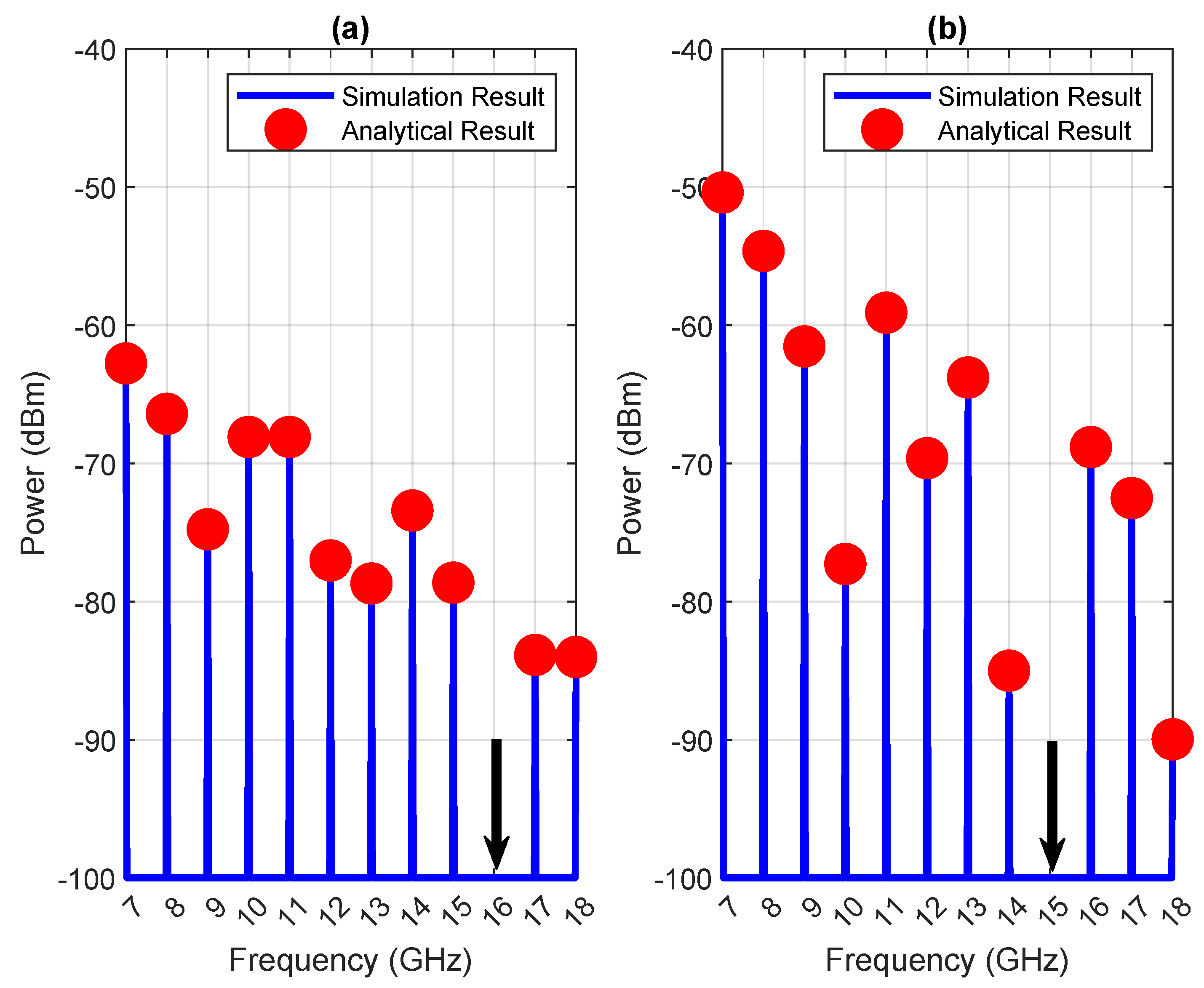
Figure 11a shows the modes for the 15 GHz frequency to be maximum and 16 suppressed, and Figure 11b shows the mode where the 16 GHz frequency is maximum and 15 suppressed. The area of the suppressed frequency is shown with a black arrow.
This functionality can be easily achieved from the proposed structure without any changes in the structure and only by adjusting the bias voltage of the modulators, which is one of the features of this structure. In addition, frequency hopping can be done for other frequencies by adjusting the bias voltage; in this section, these frequencies are only selected as samples. Moreover, it is worth mentioning that achieving Figure 10 is a consequence of having an analytical model. Therefore, one advantage of having an analytical model is optimizing the structure for specific functions.

3.2. Amplitude Shift Key Modulation (ASK)

Digital modulations are the basic foundation of digital communication and radar systems. Amplitude Shift Keying (ASK), Phase Shift Keying (PSK) and Frequency Shift Keying (FSK) modulation can be mentioned as typical digital modulations. Digital modulation, which is performed in the electrical field, has limitations such as bandwidth and high-frequency generation, which can be overcome by using MWP techniques and performing the modulation in the light field. Therefore, digital modulations that are done with MWP systems do not experience an electrical bottleneck. Reducing the Size, Weight and Power consumption (SWaP) is another advantage of MWP digital modulation.
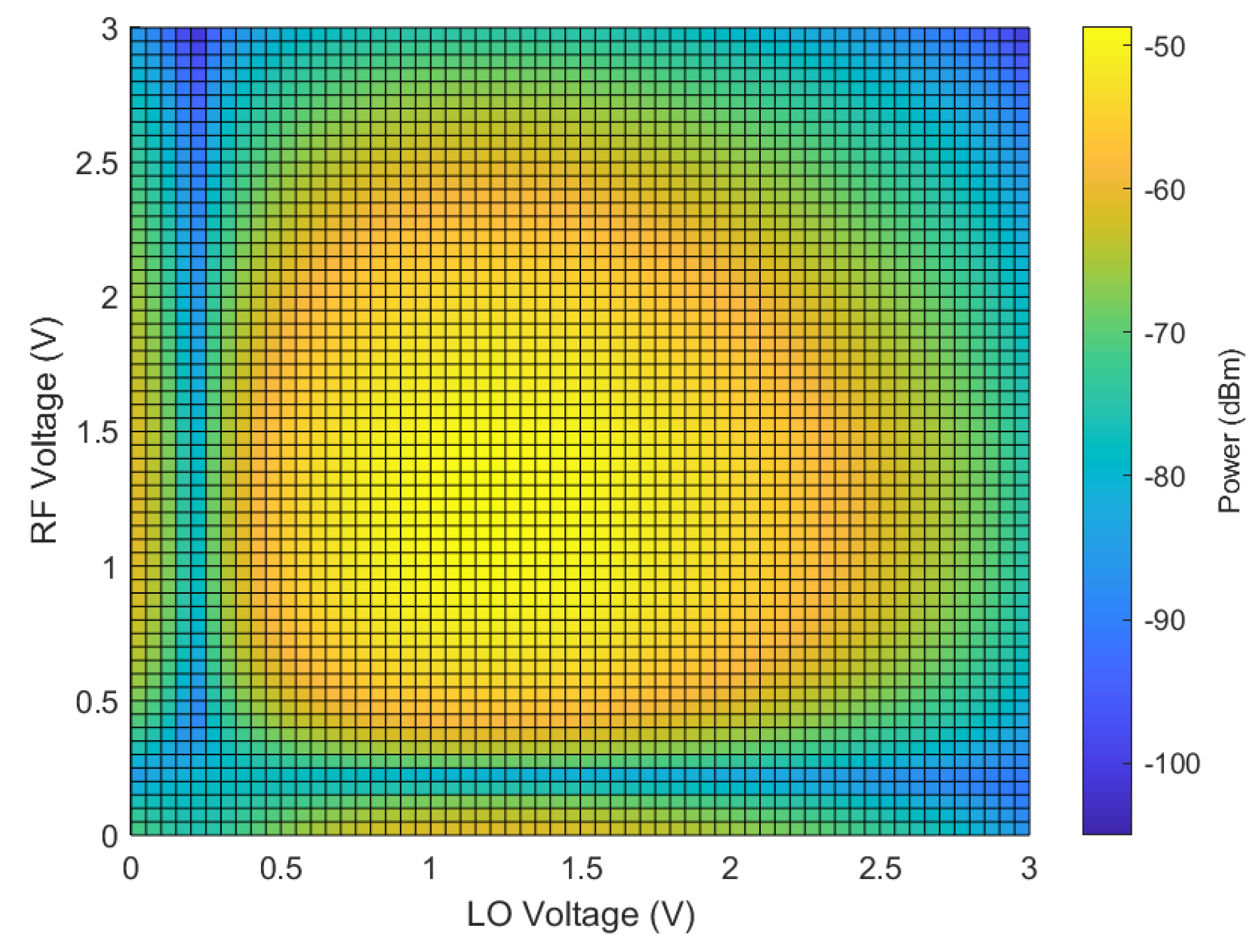
From the proposed structure and analytical expressions, we carried out ASK modulation functionality. MWP ASK digital modulation, which is presented, operates by considering the modulator’s applied bias voltages. Figure 12 shows the power level at 8 GHz frequency by considering changes in bias voltages of RF and LO modulators. With attention to the figure, some areas have higher power relative to others, so by selecting two points from the figure that have minimum and maximum power and with voltages of these points, ASK modulation can be done. The sequence of data to be modulated should be in the form of binary, where it is directly connected to the modulator bias. Therefore, with changes in modulator bias, the amplitude of desired frequency changes with respect to the sequence of the data.
In the studied case, the desired frequency is 8 GHz, V b L O is 1.5 V constant and V b R F changes between 0.3 and 1.5 V when bias voltages of modulators are 1.5 V ( V b L O ) and 0.3 V ( V b R F ). The amplitude of desired frequency is minimum relative to when the modulators’ bias voltages are 1.5 ( V b L O ) and 0.3 ( V b R F ) V according to Figure 12. Therefore, by switching the bias voltages of the modulators, the amplitude of 8 GHz frequency in proportion to the sequence of the data changes in a certain time period.
Figure 13 shows the ASK modulation by employing the proposed structure. Figure 13a shows the sequence of the data, and Figure 13b shows the normalized modulated sequence of the data on 8 GHz frequency. In addition, ASK modulation can be done for other frequencies in this section; these frequencies are only selected as examples. Again, as mentioned before, achieving Figure 12 is a consequence of having an analytical model.

3.3. Phase Shifter

Phase shifting has an important role in phase array antennae, beam forming and radar systems [32,33,34]. Microwave phase shifters have limited phase range and bandwidth and significant SWaP. However, the use of MWP can help overcome these limitations. The most important limitation of electrical phase shift is bandwidth limitation, which does not exist in MWP solutions.
The other functionality carried out from the proposed structure is phase shifting, which can control the phase of various frequencies. To illustrate, the proposed functionality was demonstrated using a 9 GHz frequency. It should be noted that this structure can control the phase of other frequencies besides 9 GHz, and the selection of 9 GHz was for illustrative purposes.
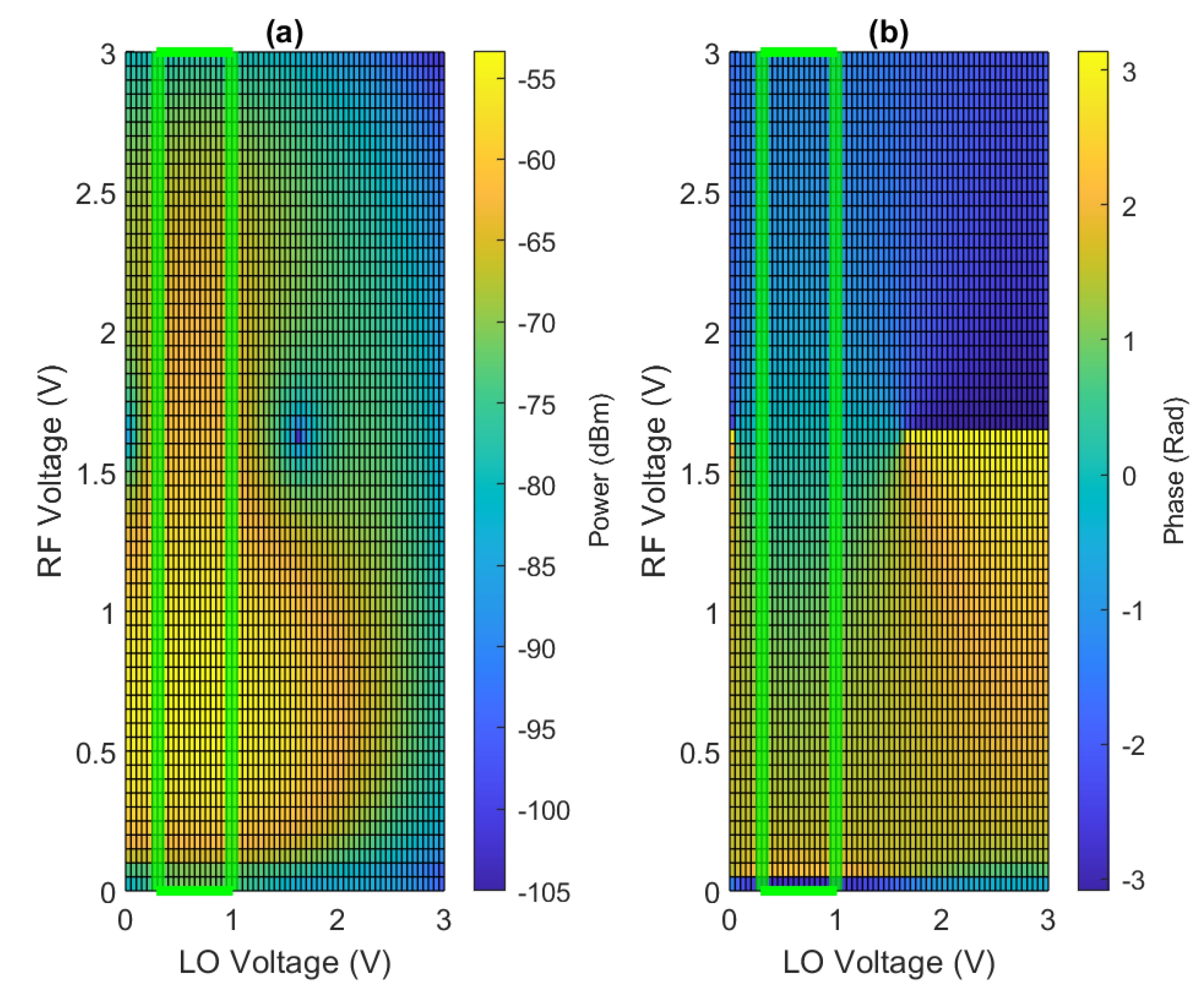
Figure 14a shows the power level at 9 GHz frequency by considering the changes in the modulators’ bias voltages, and Figure 14b shows phase behavior at 9 GHz frequency by considering the changes in the modulators’ bias voltages. According to Figure 14b, in the part inside the green area from top to bottom, the phase changes linearly between π / 2 and π / 2 approximately.
According to Figure 14a and Figure 15, in this region of the bias voltage of the modulators, the power level at the frequency of 9 GHz has a difference of 12 dB between the maximum value and the minimum value. In addition, it changes almost linearly with phase change and does not behave suddenly.
Figure 15 shows the power level with respect to the phase changes. In the selected region, for phase shifting, V b L O can have a voltage between 0.3 and 1 V, but it must be fixed because V b L O set at a fixed voltage and V b R F changing from 0 to 3 V will cause phase shifting according to Figure 14. With the change of V b R F from 0 to 3 V, phase changes in a smooth and linear behavior, which brings the ability to control the phase of desired frequency by adjusting the V b R F . Moreover, as shown in Figure 15, by changing the V b L O within the mentioned range, there is no significant difference in the phase behavior and it continues to change linearly.
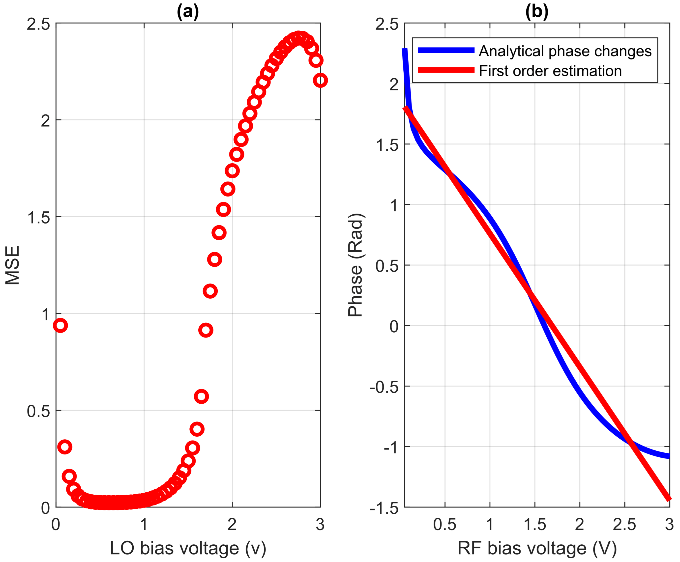
As mentioned, various LO bias voltages between 0.3 and about 1 V can be set for phase shift in structure, but all the voltages in this range are not suitable and the phase changes do not behave linearly and smoothly. Figure 16a shows the Mean Square Error (MSE) of phase changes in the range of 0 to 3 V LO bias voltages according to the estimation of first-order phase changes. As it is clear from the figure, in the range of 0.3 to 1 V, the phase changes have very little error and it has nearly linear behavior with respect to bias voltages, which shows the ability of the structure to control the phase for the mentioned applications. In addition, the error is very small in the area shown in Figure 14b.
From the results of Figure 16a, the minimum error occurs when the LO bias voltage is 0.6 volts. Therefore, the most linear behavior of the phase is obtained at this voltage. Figure 16b shows the behavior of the phase changes in the 0.6 V constant LO bias voltage in relation to the change in the RF bias voltage.

4. Conclusions

A cascaded MZM reconfigurable MWP mixer is presented, analyzed and simulated. The structure consists of two cascaded single-arm MZM modulators. Two single tone frequencies (RF and LO) are applied to MZM modulators, which makes this structure a MWP mixer. The general analytic model for the spectra (both power and phase) of a PM, MZM and mixer is derived and verified by the simulation results. In the proposed model, the nonlinear behavior of PM is considered, which makes this model more general and independent of the electro-optic platform. The proposed analytic model enables us to optimize the structure for different functionalities, such as frequency hopper, ASK modulator and phase shifter in some frequencies, by changing the bias voltages applied to MZMs. Having analytical expressions of the spectra, these configurations were investigated, and the performance of the structure in these configurations is discussed. The frequency hopping configuration was reached by suppressing one frequency while maximizing another neighbor frequency. The ASK modulator configuration is optimized by finding maximum and minimum power at a special frequency for applied bias voltages. Phase shifting occurred in some frequencies where they have the most linear phase behavior while having constant power behavior simultaneously.

Author Contributions

Conceptualization, E.D., H.K and P.M.; software, E.D. and H.K.; validation, E.D and H.K; data curation, E.D. and H.K; writing—original draft preparation, E.D.; supervision, H.K. and P.M.; project administration, H.K.; funding acquisition, P.M. All authors have read and agreed to the published version of the manuscript.

Funding

This research received no external funding.

Acknowledgments

This work was partially supported by the MSCA RISE programme through project DIOR (grant agreement no. 10100828) and by FEDER, through the CENTRO 2020 programme project ORCIP (CENTRO-01-0145-FEDER-022141).

Conflicts of Interest

The authors declare no conflict of interest.

References

  1. Capmany, J.; Novak, D. Microwave photonics combines two worlds. Nat. Photonics 2007, 1, 319. [Google Scholar] [CrossRef]
  2. Juodawlkis, P.W.; Twichell, J.C.; Betts, G.E.; Hargreaves, J.J.; Younger, R.D.; Wasserman, J.L.; O’Donnell, F.J.; Ray, K.G.; Williamson, R.C. Optically sampled analog-to-digital converters. IEEE Trans. Microw. Theory Tech. 2001, 49, 1840–1853. [Google Scholar] [CrossRef] [Green Version]
  3. Capmany, J.; Ortega, B.; Pastor, D. A tutorial on microwave photonic filters. J. Light. Technol. 2006, 24, 21–29. [Google Scholar] [CrossRef]
  4. Supradeepa, V.R.; Long, C.M.; Wu, R.; Ferdous, F.; Hamidi, E.; Leaird, D.E.; Weiner, A.M. Comb-based radiofrequency photonic filters with rapid tunability and high selectivity. Nat. Photonics 2012, 6, 186–194. [Google Scholar] [CrossRef] [Green Version]
  5. Loo, R.Y.; Tangonan, G.L.; Yen, H.W.; Jones, V.L.; Ng, W.W.; Lewis, J.B.; Lee, J.J.; Livingston, S. Photonics for phased-array antennas. Photonics Radio Freq. 1996, 2844, 234–240. [Google Scholar]
  6. Tang, Z.; Li, Y.; Yao, J.; Pan, S. Photonics-based microwave frequency mixing: Methodology and applications. Laser Photonics Rev. 2020, 14, 1800350. [Google Scholar] [CrossRef]
  7. Winnall, S.T.; Lindsay, A.C.; Knight, G.A. A wide-band microwave photonic phase and frequency shifter. IEEE Trans. Microw. Theory Tech. 1997, 45, 1003–1006. [Google Scholar] [CrossRef]
  8. Khan, M.H.; Shen, H.; Xuan, Y.; Zhao, L.; Xiao, S.; Leaird, D.E.; Weiner, A.M.; Qi, M. Ultrabroad-bandwidth arbitrary radiofrequency waveform generation with a silicon photonic chip-based spectral shaper. Nat. Photonics 2010, 4, 117–122. [Google Scholar]
  9. Yao, J.; Zeng, F.; Wang, Q. Photonic generation of ultrawideband signals. J. Lightwave Technol. 2007, 25, 3219–3235. [Google Scholar]
  10. Liu, Y.Q.; Sun, J.; Shu, Y.; Wu, L.; Lu, L.; Qi, K.; Che, Y.; Li, L.; Yin, H. High numerical aperture and large focusing efficiency metalens based on multilayer transmitarray elements. Opt. Lasers Eng. 2021, 147, 106734. [Google Scholar] [CrossRef]
  11. Liu, Y.Q.; Ren, Z.; Shu, Y.; Wu, L.; Sun, J.; Cai, H.; Zhang, X.; Lu, L.; Qi, K.; Li, L.; et al. Broadband, large-numerical-aperture and high-efficiency microwave metalens by using a double-layer transmissive metasurface. Appl. Phys. Express 2022, 15, 014003. [Google Scholar]
  12. Maleki, L. The optoelectronic oscillator. Nat. Photonics 2011, 5, 728–730. [Google Scholar] [CrossRef]
  13. Yao, X.S.; Maleki, L. Optoelectronic microwave oscillator. JOSA B 1996, 13, 1725–1735. [Google Scholar] [CrossRef]
  14. Liu, M.; Yin, X.; Ulin-Avila, E.; Geng, B.; Zentgraf, T.; Ju, L.; Wang, F.; Zhang, X. A graphene-based broadband optical modulator. Nature 2011, 474, 64–67. [Google Scholar] [CrossRef] [PubMed]
  15. Gu, T.; Petrone, N.; McMillan, J.; van der Zande, A.; Yu, M.; Lo, G.Q.; Kwong, D.L.; Hone, J.; Wong, C.W. Regenerative oscillation and four-wave mixing in graphene optoelectronics. Nat. Photonics 2012, 6, 554–559. [Google Scholar] [CrossRef] [Green Version]
  16. Zhang, H.; Tang, D.; Zhao, L.; Bao, Q.; Loh, K.P. Vector dissipative solitons in graphene mode locked fiber lasers. Opt. Commun. 2010, 283, 3334–3338. [Google Scholar] [CrossRef] [Green Version]
  17. Paris, M.G.A.; Genoni, M.G.; Shammah, N.; Teklu, B. Quantifying the nonlinearity of a quantum oscillator. Phys. Rev. A Mol. Opt. Phys. 2014, 90, 012104. [Google Scholar] [CrossRef] [Green Version]
  18. Teklu, B.; Ferraro, A.; Paternostro, M.; Paris, M.G.A. Nonlinearity and nonclassicality in a nanomechanical resonator. EPJ Quantum Technol. 2015, 2, 1–10. [Google Scholar] [CrossRef] [Green Version]
  19. Olivares, S.; Cialdi, S.; Castelli, F.; Paris, M.G.A. Homodyne detection as a near-optimum receiver for phase-shift-keyed binary communication in the presence of phase diffusion. Phys. Rev. A Mol. Opt. Phys. 2013, 87, 050303. [Google Scholar]
  20. Chan, E.H.W.; Minasian, R.A. Microwave photonic downconverter with high conversion efficiency. J. Lightwave Technol. 2012, 30, 3580–3585. [Google Scholar] [CrossRef]
  21. Gopalakrishnan, G.K.; Moeller, R.P.; Howerton, M.M.; Burns, W.K.; Williams, K.J.; Esman, R.D. A low-loss downconverting analog fiber-optic link. IEEE Trans. Microw. Theory Tech. 1995, 43, 2318–2323. [Google Scholar] [CrossRef]
  22. Keshavarz, H.; Hosseini, S.E.; Jamshidi, K.; Plettemeier, D. Silicon Photonic-Based Integrated Microwave Photonic Reconfigurable Mixer, Phase Shifter, and Frequency Doubler. J. Light. Tech. 2021, 39, 7698–7705. [Google Scholar] [CrossRef]
  23. Zhang, W.; Wen, A.; Gao, Y.; Li, X.; Shang, S. Microwave photonic frequency conversion with high conversion efficiency and elimination of dispersion-induced power fading. IEEE Photonics J. 2016, 8, 5500909. [Google Scholar] [CrossRef]
  24. Jiang, T.; Wu, R.; Yu, S.; Wang, D.; Gu, W. Microwave photonic phase-tunable mixer. Opt. Express 2017, 25, 4519–4527. [Google Scholar] [CrossRef] [PubMed]
  25. Tang, Z.; Pan, S. Reconfigurable microwave photonic mixer with minimized path separation and large suppression of mixing spurs. Opt. Lett. 2017, 42, 33–36. [Google Scholar] [CrossRef] [Green Version]
  26. Li, H.; Zhao, S.; Lin, T.; Zhang, K.; Jiang, W.; Wang, G.; Li, X. A filterless reconfigurable frequency mixer based on a wideband photonic microwave phase shifter. Opt. Commun. 2020, 475, 126224. [Google Scholar] [CrossRef]
  27. Urick, V.J.; Williams, K.J.; McKinney, J.D. Fundamentals of Microwave Photonics; John Wiley & Sons: Hoboken, NJ, USA, 2015. [Google Scholar]
  28. Abramowitz, M.; Stegun, I.A. Handbook of Mathematical Functions with Formulas, Graphs, and Mathematical Tables; National Bureau of Standards Applied Mathematics Series 55. Tenth Printing; ERIC: Fort Collins, CO, USA, 1972.
  29. Keshavarz, H.; Hosseini, S.E.; Abiri, H.; Jamshidi, K.; Plettemeier, D. Bias-Free Silicon-Based Optical Single-Sideband Modulator without 2nd-Order Sideband. IEEE Photonics J. 2020, 12, 5501816. [Google Scholar] [CrossRef]
  30. Cox, C.H. Analog Optical Links: Theory and Practice; Cambridge University Press: Cambridge, UK, 2006. [Google Scholar]
  31. Liu, Q.; Fok, M.P. Ultrafast and wideband microwave photonic frequency-hopping systems: A review. Appl. Sci. 2020, 10, 521. [Google Scholar] [CrossRef] [Green Version]
  32. Pan, S.; Zhang, Y. Tunable and wideband microwave photonic phase shifter based on a single-sideband polarization modulator and a polarizer. Opt. Lett. 2012, 37, 4483–4485. [Google Scholar] [CrossRef] [Green Version]
  33. Niu, T.; Wang, X.D.; Chan, E.H.; Feng, X.; Guan, B.O. Dual-polarization dual-parallel MZM and optical phase shifter based microwave photonic phase controller. IEEE Photonics J. 2016, 8, 5501114. [Google Scholar] [CrossRef]
  34. Pan, S.; Ye, X.; Zhang, Y.; Zhang, F. Microwave photonic array radars. IEEE J. Microw. 2021, 1, 176–190. [Google Scholar] [CrossRef]
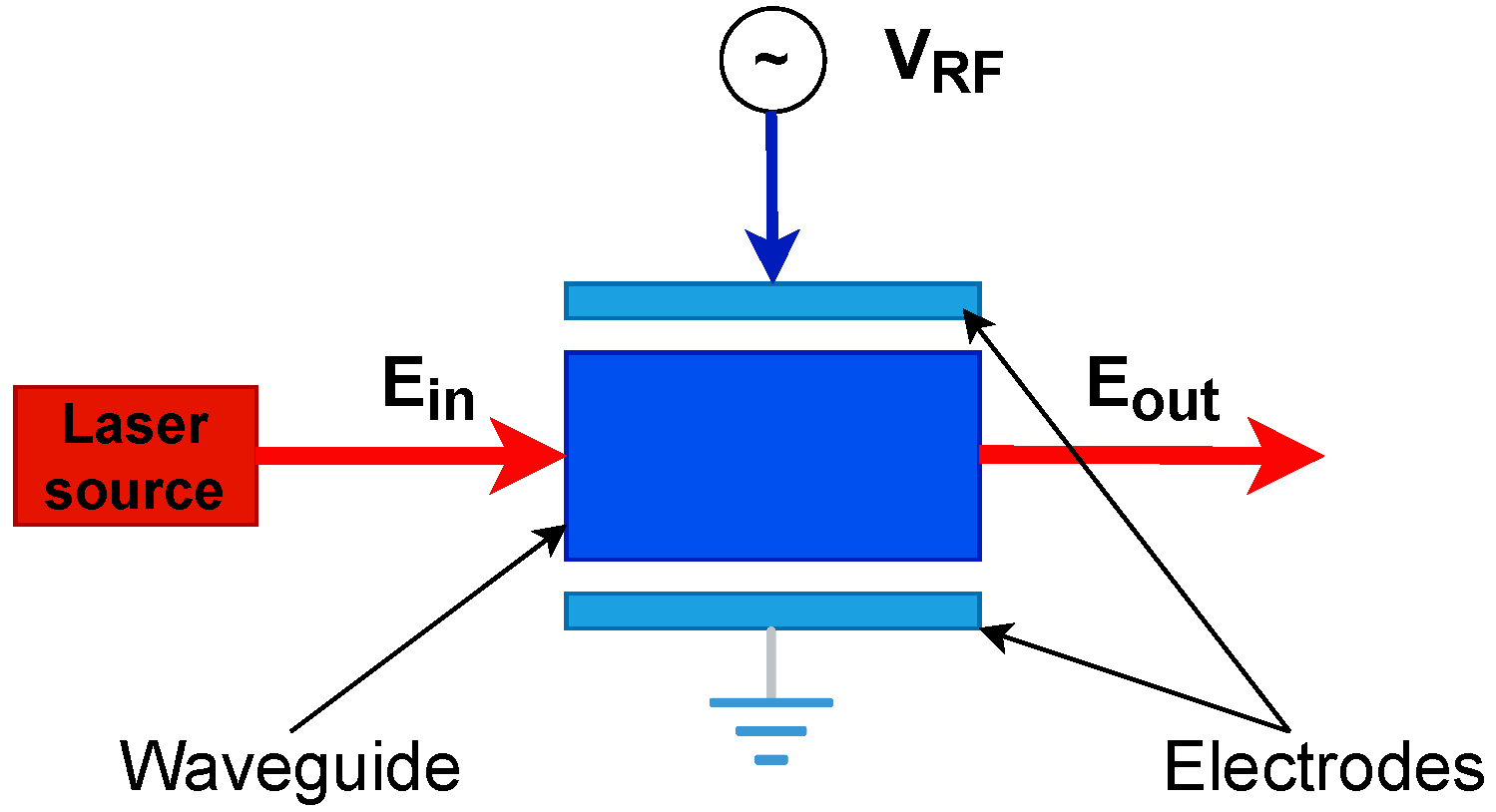
Figure 1. Phase modulator or electro-optic modulator. The blue lines refer to electrical paths and the red lines refer to optical paths.
Photonics 10 00916 g001
Figure 2. Refractive index behavior by changing applied voltage.
Photonics 10 00916 g002
Figure 3. (a) Optical carrier phase changes for PM, (b) optical output power for MZM.
Photonics 10 00916 g003
Figure 4. Cascaded MZM mixer that employs single arm MZM. The blue lines refer to electrical paths and the red lines refer to the optical paths. PM: phase modulator.
Photonics 10 00916 g004
Figure 5. Nonlinear mixer optical spectrum according to Table 1 parameters.
Photonics 10 00916 g005
Figure 6. Optical spectrum comparison of mixers with linear and nonlinear modulator behavior according to Table 1 parameters.
Photonics 10 00916 g006
Figure 7. Mixer electrical spectrum.
Photonics 10 00916 g007
Figure 8. Electrical spectrum comparison of mixers with linear and nonlinear modulators.
Photonics 10 00916 g008
Figure 9. IF conversion loss.
Photonics 10 00916 g009
Figure 10. Power difference between 15 GHz and 16 GHz by changing RF and LO modulator bias.
Photonics 10 00916 g010
Figure 11. Frequency hopping operation for 16 GHz (a) and 15 GHz (b).
Photonics 10 00916 g011
Figure 12. Power level at 8 GHz frequency by changing RF and LO modulator bias.
Photonics 10 00916 g012
Figure 13. (a) Sequence of the data applied to RF modulator; (b) simulated normalized modulated signal at 8 GHz.
Photonics 10 00916 g013
Figure 14. (a) Power level with respect to the bias voltage changes at 9 GHz frequency. (b) phase of 9 GHz frequency with respect to the bias voltages changes.
Photonics 10 00916 g014
Figure 15. Power level with respect to the phase changes at 9 GHz frequency.
Photonics 10 00916 g015
Figure 16. (a) MSE of phase changes related to linear estimation (b) Comparison between phase changes and its linear estimation for minimum MSE at V b L O = 0.6 volt.
Photonics 10 00916 g016
Table 1. Nonlinear and linear refractive index model coefficients.
Model p 2 p 1 p 0
Nonlinear 1.6 × 10 5 10 × 10 5 0.1 × 10 5
Linear0 5.2 × 10 5 2.499 × 10 5
Disclaimer/Publisher’s Note: The statements, opinions and data contained in all publications are solely those of the individual author(s) and contributor(s) and not of MDPI and/or the editor(s). MDPI and/or the editor(s) disclaim responsibility for any injury to people or property resulting from any ideas, methods, instructions or products referred to in the content.