Abstract
Plasmonics is the study of resonant oscillations of free electrons in metals caused by incident electromagnetic radiation. Surface plasmons can focus and steer light on the subwavelength scale. Apart from metals, plasmonic phenomena can be observed in soft matter systems such as electrolytes which we study here. Resonant charge oscillations can be induced for ions in solution, however, due to their larger mass, they are plasmon-active in a lower frequency regime and on a larger wavelength scale. Our investigation focuses on spatial confinement which allows increasingly strong charge interactions and gives rise to nonlocality or spatial dispersion effects. We derive and discuss the nonlocal optical response of ionic plasmons using a hydrodynamic two-fluid model in a planar homogeneous three-layer system with electrolyte-dielectric interfaces. As in metals, we observe the emergence of additional longitudinal propagation modes in electrolytes which causes plasmonic broadening. Studying such systems enables us to identify and understand plasmonic phenomena in biological and chemical systems.
1. Introduction
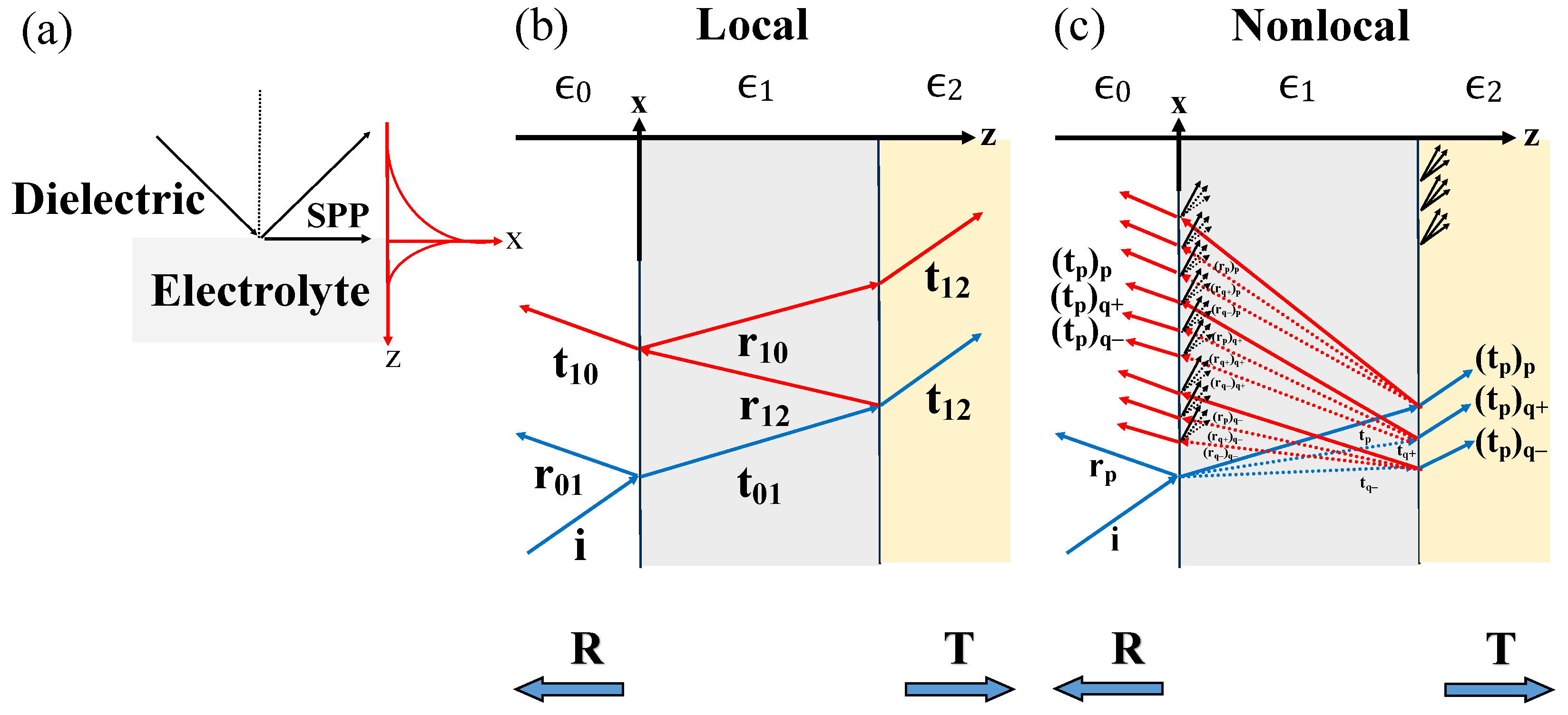
Free electrons in the conduction band of metals can be resonantly excited by incident light to form collective oscillations. If confined to a nanostructure in a dielectric environment, they form surface plasmons (SPs) manifesting along the conducting interface. At planar interfaces, surface plasmon polaritons (SPPs) are formed which propagate along the metal-dielectric interface with a higher parallel momentum compared to light in a vacuum, while they decay exponentially away from the interface, as depicted in Figure 1a. Consequently, they benefit from a long lifetime and enable the concentration of electromagnetic fields within dimensions approximately equal to or smaller than their wavelength [1]. Apart from metals, graphene-based structures exhibit such plasmonic properties in the THz regime [2,3,4,5]. This opens numerous possibilities for nanoscale applications including light generation and concentration through confinement effects [6,7], the enhancement of nonlinear phenomena [8,9,10,11,12], optical data storage [13,14], improved solar cells [15,16,17] and photocatalysis [18], sensing down to the molecular level [19,20], surface-enhanced Raman spectroscopy [21,22], structure-induced colors [23,24], and much more.
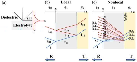
Figure 1.
(a) Surface plasmon polariton (SPP) propagation and its evanescent decay perpendicular to a dielectric-electrolyte interface. (b) In the local response approximation (LRA), a three-layer-system with dielectric constants , and shows the common multiple reflections for a single transversal mode. (c) With nonlocal optical response (NOR), multiple reflections of several modes of transversal and longitudinal character occur inside the electrolyte layer. Indices have been simplified.
Experimental observations show that short-ranged electron-electron interactions change the spectral profile of plasmons [25], which is contrary to the size-independence predicted by classical electrodynamics in the local response approximation (LRA). At length scales where the mean free path of valence electrons is similar to the particle diameter, quantum effects emerge leading to additional loss channels. Noble metal nanostructures [26,27,28,29], metallic dimers [27,30,31,32,33], and nanostructures with sub-nanometer gaps [34] exhibit significant blueshifts and quenching of their classically predicted near-field intensity.
To describe such effects, the hydrodynamic Drude model (HDM) is commonly integrated into standard computational nanophotonics methods. Spatial dispersion in metals has been described with the finite element method (FEM) [35], the analytical Wentzel-Kramers-Brillouin (WKB) method [35], time-dependent local density approximation (TDLDA) [31], Fourier modal method (FMM) [36], and transformation optics (TO) [29]. To account for convection and electron diffusion, the HDM can be expanded into the generalized nonlocal optical response (GNOR) model [29,37,38,39].
Typically, plasmonics refers to the resonant excitation of the electron plasma. However, ionic charge carriers in soft matter such as membranes, biopolymers, liquid crystals, and complex fluids [40,41] also exhibit plasmonic behavior. These materials have a heterogeneous structure with sizes ranging from nanoscale to a few micrometers. Ions are much heavier than electrons, their concentration is much lower and their velocity depends on local temperature as we will detail below. Consequently, different design principles and adapted analytical theories of plasmonics are needed to conceive soft matter systems that leverage plasmonic light-matter interactions. Ionic plasmon-polaritons have been investigated for spherical electrolytes, embedded, e.g., in an insulating membrane and chains thereof. Such models provide an alternative description of saltatory conduction observed in nerve cells [42]. In addition, loss mechanisms beyond classical electrodynamics such as size-dependent plasmon damping, ohmic-type energy dissipation, and radiative losses were discussed [43,44]. Nonlocal effects in soft plasmonics were investigated in spherical electrolyte systems using a two-fluid hydrodynamic model [44]. Such a two-fluid model was furthermore used to investigate nonlocal interactions in electron-hole pairs of semiconductors [45,46]. A generalized multi-fluid model has recently been developed [47].
In this article, we study the plasmonic properties of ions in solution analogous to electrons in metals at planar homogeneous dielectric-electrolyte interfaces in systems depicted in Figure 1b,c, developing an analytic nonlocal two-fluid model that includes short-ranged non-classical interactions between the charge carriers resulting in spatial dispersion effects. Our study can provide insights into the underlying physics of ionic phenomena in biological and chemical systems. Soft plasmonics allows a different perspective on energy transfer and the interaction of electrolytes with surfaces, e.g., in photocatalytic processes, could be described more efficiently using computational tools from nanophotonics. In biological systems, the confinement of an electrolyte into a liquid layered system can be achieved by thin membranes separating the different layers. An example is signaling in nerve cells (axons) where a cord connects several myelinated axons. Within and without the myelinated sheaths, electrolytes of different concentrations and compositions are interfacing. This enables a plasmon-polariton model in chains of myelinated axons [48,49] providing insights into the treatment of demyelination syndromes such as multiple sclerosis caused due to perturbation of neuro-signaling in myelinated axons. Studying biological systems through the lens of plasmonic properties may allow us to find different routes to diagnose, study and combat such diseases.
2. Methodology
2.1. Classical Soft Plasmonics—General Characteristics of Ionic Systems
Similarly to how electrons behave in metals, negative (−) ions in a fluid are displaced toward positive (+) ions and vice versa due to material polarization, leading to bulk plasma oscillations for each type of ion with frequency
which depends on their respective charge , mass , and concentration [44]. Both positive and negative ions carry equal but opposite charge parities in our chosen materials. More generally, total charge balance is demanded, i.e., . Throughout this work, we set the ion concentration to , with the Avagadro constant .
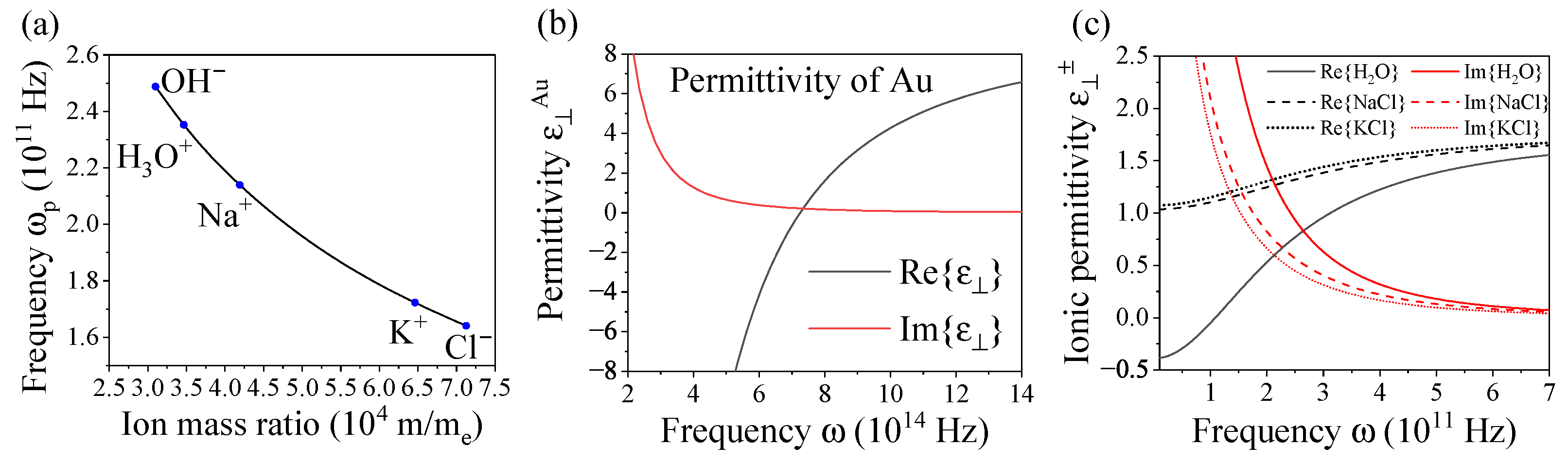
The ions are scattered throughout the entire electrolyte system and in principle move freely within the solution. The movement of ions within the electrolyte is influenced by their relatively large mass. Their mass is approximately times greater than the mass of an electron, see Table 1. Ions exhibit a velocity determined by their sensitivity to thermal fluctuations, their thermal velocity , with values below m/s at K. Notably, ions of greater mass such as K and Cl are slower than lighter ions such as OH and HO. In contrast, free electrons in metals travel at a much higher speed, characterized by their Fermi velocity , which is typically three to four orders of magnitude larger, e.g., for gold (and similarly for silver) m/s [44]. Figure 2a shows that the values of ionic fall within the range of a few hundred GHz with heavier ions exhibiting decreasing values. Therefore, the plasmonic optical response of ionic systems occurs predominantly in the far-infrared.

Table 1.
Characteristic material parameters of ionic systems [44].
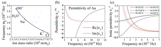
Figure 2.
(a) Bulk plasmon frequency of OH, HO, Na, K, and Cl ions in solution varying with their respective ion mass ratios with ion concentration , where is the Avogadro constant. (b) Dielectric permittivity of Au in a simple Drude model varying with frequency using parameters Hz, Hz, [50]. (c) Dielectric ionic permittivity of HO, NaCl, and KCl ions in solution varying with frequency and with parameters as in Table 1 and background permittivity .
When considering the contribution of both negative and positive ions to the optical response of an electrolyte, the dielectric Drude permittivity of ions can be employed as
Negative and positive ions operate with distinct plasmon bulk and damping frequencies calculated from their viscosities; refer to Table 1 [44]. To illustrate the basic plasmonic characteristics of ions, we compare them to gold in a simple Drude model for the sake of clarity. Figure 2b shows the dielectric function for Au enabling comparability with the behavior of ions in solution, Figure 2c. Apart from operating in a distinct frequency range, ionic plasmons exhibit a typical plasmonic behavior similar to that of Au, which allows for identifying the resonance condition at a planar interface . It should be noted that the dielectric permittivity is significantly lower for ions than that of noble metals such as Au () as it is determined by the solution in which the electrolytes move. Instead of a liquid, lipid matter with slightly higher could be used. Neglecting damping, the resonance frequency at a planar metal interface is obtained from
which in the case of ions becomes
Finally, the dispersion relation of p-polarized SPPs that propagate at the interface separating two media as depicted in Figure 1b is given by
In Figure 3, we compare the analytical dispersion curve with the calculated energy flux in the reflection of a Au-water interface, Figure 3a, with ionized HO confined in neutral water to a slab of thickness mm in Figure 3b. In biological systems, such confinement can be achieved by thin membranes separating the different layers. Note that the permittivity of water is almost constant in the relevant frequency range. The left side of the light line, the black line defined by , represents propagating waves, while the right side corresponds to the excitation of bound SPPs. This excitation occurs for [1]. Due to realistic damping in the system, propagating modes occur above the resonance frequency and bound modes show a finite width. While we observe the typical strong dispersion in Au due to the abundance of free electrons, the same signature is present in electrolytes with low concentration.
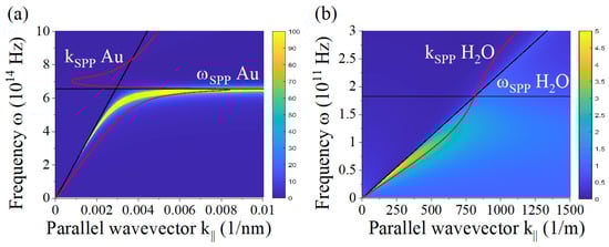
Figure 3.
Analytical dispersion (red curves) and reflected energy flux for (a) a Au-water interface and (b) ionized HO in a slab of thickness mm. The position of and the light line (black curves) are marked for reference. Tabulated data was used for Au [50].
2.2. Nonlocal Interactions in Dielectric-Electrolyte Multilayered Systems
Nonlocal phenomena occur when charge carriers interact over short length scales, typically promoted by strong spatial confinement [51]. This section focuses on nonlocal effects arising from ion-ion interactions driven by Coulombic forces in planar homogeneous multilayers. In order to study such systems, we apply the HDM to a two-fluid system [44]. In this framework, it was shown for ionic spheres that spatial dispersion yields less pronounced blueshifts of their plasmon resonances compared to metals [44].
The ion-ion interaction is described by the linearized Navier-Stokes equation
for an incident light field . The charges are treated separately in the usual wave equation as external current and charge densities arising from each charge carrier type. The nonlocal strength quantifies the interaction caused by internal pressure of the charge carriers. The Helmholtz equation for a nonlocal ionic system becomes
where , leading to a system of a total of three coupled equations.
An important manifestation of spatial dispersion is the emergence of longitudinal waves in addition to the usual transversal modes obtained by the Navier-Stokes equation as pressure waves of charge carriers. The classical transversal and additional longitudinal waves are superimposed in the nonlocal medium. The nonlocal wave vectors associated with the propagation of individual longitudinal ionic modes in a medium are
where is the individual permittivity of each type of ion, which is not to be confused with the total ionic permittivity of the electrolyte given by , see Equation (2).
The coupled nonlocal wave equations of each type of ion can be combined into a single differential equation, symmetric with respect to the indicated signs, that results in a nonlocal wave equation of fourth order
This gives rise to a fourth-power equation whose symmetric complex-valued roots describe the oscillations of positive and negative ions in an electrolyte system. Assuming a planar system and propagation in the z-direction, the component of the wave vector of interest is while the parallel component remains unchanged throughout the structure.
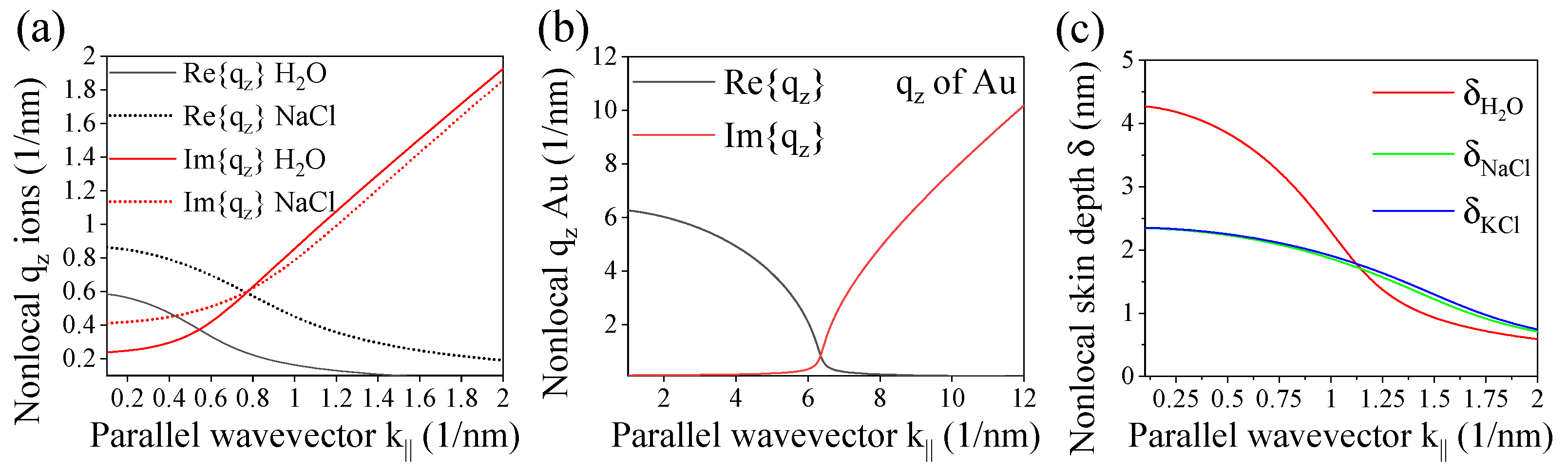
Figure 4a shows the resulting total nonlocal wave vector as a function of the parallel wave vector necessary to excite the longitudinal modes at planar interfaces. For the chosen frequency Hz, the values are in the range of 0.1–2 nm. Interestingly, a similar length scale is found for Au surfaces as depicted in Figure 4b. The wave vector in the propagation direction is connected to the penetration depth of the SPP waves that evanescently decay in the z-direction. The penetration or skin depth of nonlocal modes is given by , which is of the order of 1 to 5 nm as depicted in Figure 4c for the ions.
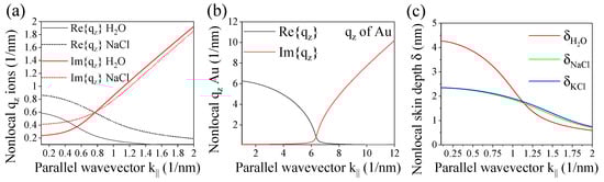
Figure 4.
(a) Real and imaginary part of the nonlocal wave vector of ions in solution varying with the parallel wave vector for frequency Hz. (b) Same for Au at frequency Hz. (c) Nonlocal skin depth of ions in solution.
3. Results and Discussion
3.1. Nonlocal Optical Coefficients for Finite Multilayers
In this section, we derive the optical coefficients at planar dielectric-electrolyte interfaces with either transversal or longitudinal incident modes as illustrated in Figure 1c. The usual boundary conditions, i.e., the continuity of the parallel field components of the electric and magnetic fields, are applied next to an additional boundary condition (ABC) emerging from the differential equation central to the hydrodynamic model for each type of ion. The ABC confines the charge carriers to the nonlocal medium and prohibits them from entering the dielectric local environment. In a hard-wall boundary approach, it is given by , where is the surface normal and determines the amplitude of longitudinal waves. Due to the overall micrometer size of ionic systems and larger mass of individual ions than compared to electrons, further surface effects are negligible [44,52,53].
The system is, thus, described by a total of three possible modes, the transversal p and longitudinal excitations, through their wave vectors in z-direction and given by the roots of the fourth-power Equation (9) discussed above.
In general, several distinct cases are possible. Within the dielectric, only the transversal mode (p) can be excited. At a dielectric-electrolyte interface, i.e., light incident from the dielectric side and propagation in -direction, the light transmitted into the electrolyte medium excites a transversal and both longitudinal modes according to their respective transmission coefficients. On the other hand, in reflection, only the transversal mode (p) remains. For an electrolyte-dielectric interface, any of the three modes may be incident on the interface and likewise reflected back into the electrolyte, but again, in transmission only the transversal mode will be excited.
Let us consider as an examplary case light incident from the dielectric side, characterized by permittivity . It is partially reflected back into the dielectric medium as and the remainder is transmitted into the electrolyte medium of permittivity and divided into three modes, namely the transversal mode , and the longitudinal modes . Solving the three boundary conditions mentioned above leads to the nonlocal Fresnel coefficients for a two-fluid system.
where and stem from the nonlocal properties with
Finally, the ABC connects the longitudinal modes with the transversal mode via
In the (local) limit , the common Fresnel coefficients of the LRA can be retrieved, i.e., for planar systems all coefficients become local at normal incidence as at least some parallel momentum is needed to excite the longitudinal modes. Further details, e.g., on the additional nonlocal function can be found in the Appendix A.
For a three-layered system, e.g., an electrolyte layer of finite width d in neutral solution as depicted in Figure 1c, a high degree of complexity regarding the involved modes emerges due to the multiple reflection events as each interaction with an interface creates three further excitations.
Let us consider the total transmission coefficient T. The part of the incident light that transmits into the electrolyte medium splits into three modes with amplitudes , , and . When reaching the second interface, these modes can transmit into the second dielectric medium with amplitude or be reflected back as , , and . A second index is necessary to indicate both the original mode and the type of mode that was excited by it, as the respective optical coefficients differ from each other. Further internal reflections occur and all triple possibilities with the respective double index are [, , ], [, , ], and [, , ]. For transmission, all contributions exiting the second interface towards the outer medium are summed up. Depending on the nature of the wave incident to the interface, the related coefficients are [, , and ]. The described optical paths are the typical multiple reflections observed in a Fabry-Pérot setup, however, each interaction with an interface creates three modes inside the nonlocal electrolyte. This allows writing the total reflection and transmission coefficients in the known manner. All related electric fields are superimposed and contribute to the total transmission coefficient T
where and are the transmission contributions from the three excitations
They describe the initial transmission step into the electrolyte layer and the final transmission step into the outer dielectric layer, respectively. The term describes the multiple internal reflections. Here, all possible modes are excited and this contribution becomes rather involved. The analytic expression can be found in the Appendix B.
The total reflection coefficient R can be derived in a similar manner and can be cast into the standard form for a three-layer system
where the coefficient describing the inner multiple reflections, , is unchanged. The term describes the reflection at the second interface and can be found in the Appendix B. and contain the initial transmission into the electrolyte layer and the final transmission back into the front layer. They are given by
It is notable that from analyzing the optical paths of all modes, both the total transmission and reflection for the case of nonlocal interaction between ions can be cast into the familiar form known from classical electrodynamics. While the contributions are given by summations of transversal and longitudinal solutions, this analysis allows for systematically increasing the complexity to multi-fluid systems with more distinct constituents.
3.2. Evaluating Three-Layer Systems
In an experimental setup, reflection and transmission are measured in terms of energy flux retrieved from the time-averaged real part of the Poynting vector . The flux of light incident in the dielectric is , and changes for reflected light to , and results for transmitted light in , where . From this, we calculate the reflected and transmitted energy flux
The wave vectors in the dielectric media are and . Note that the flux can be greater than 1 in the evanescent regime at high parallel momenta, however, the flux of the associated evanescent waves does not carry energy.
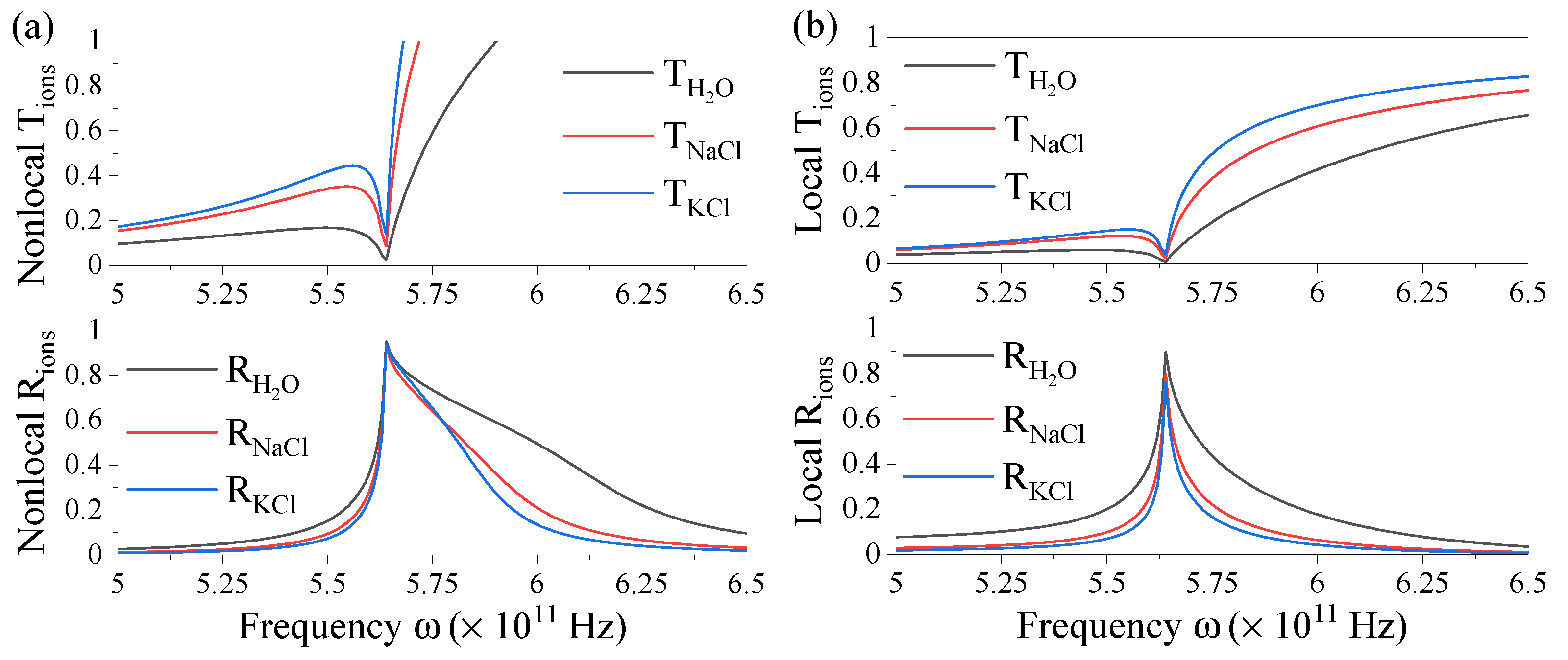
We compare spectra of the fluxes for a nonlocal system in a water-electrolyte-water configuration with its local case in Figure 5 using the material parameters given in Table 1 for the different ionic systems. Firstly, we consider in Figure 5a a nonlocal electrolyte layer with thickness mm at a fixed parallel momentum. We observe a considerable amount of plasmonic resonance broadening for the in the upper and in the lower panel as compared to the sharp resonances in the local case in Figure 5b, in particular for the resonant reflection. The broadening is stronger for lighter ions. This is due to the nonlocal strength parameter being larger for faster ions, which is the case for the lighter ions since the thermal velocity is inversely proportional to their mass.
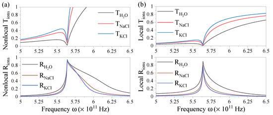
Figure 5.
Transmission (upper panel) and reflection spectra (lower panel) of ions in solution in the (a) nonlocal and (b) local case for an electrolyte layer of thickness mm and with parallel momentum m.
The flux can become larger than 1 in the evanescent regime where . The transition into this regime occurs past the resonance frequency and explains the increase observed in T. The associated modes are evanescent and do not carry information at this large parallel momentum. For reasonably low parallel momentum, the measurable transmission converges to the local result. Hence, the measured transmission will reach close to 100% in this regime which can still be assessed from . The absorption reaching zero beyond the resonance frequency can additionally be seen in Figure 2c since the imaginary part of the permittivity vanishes.
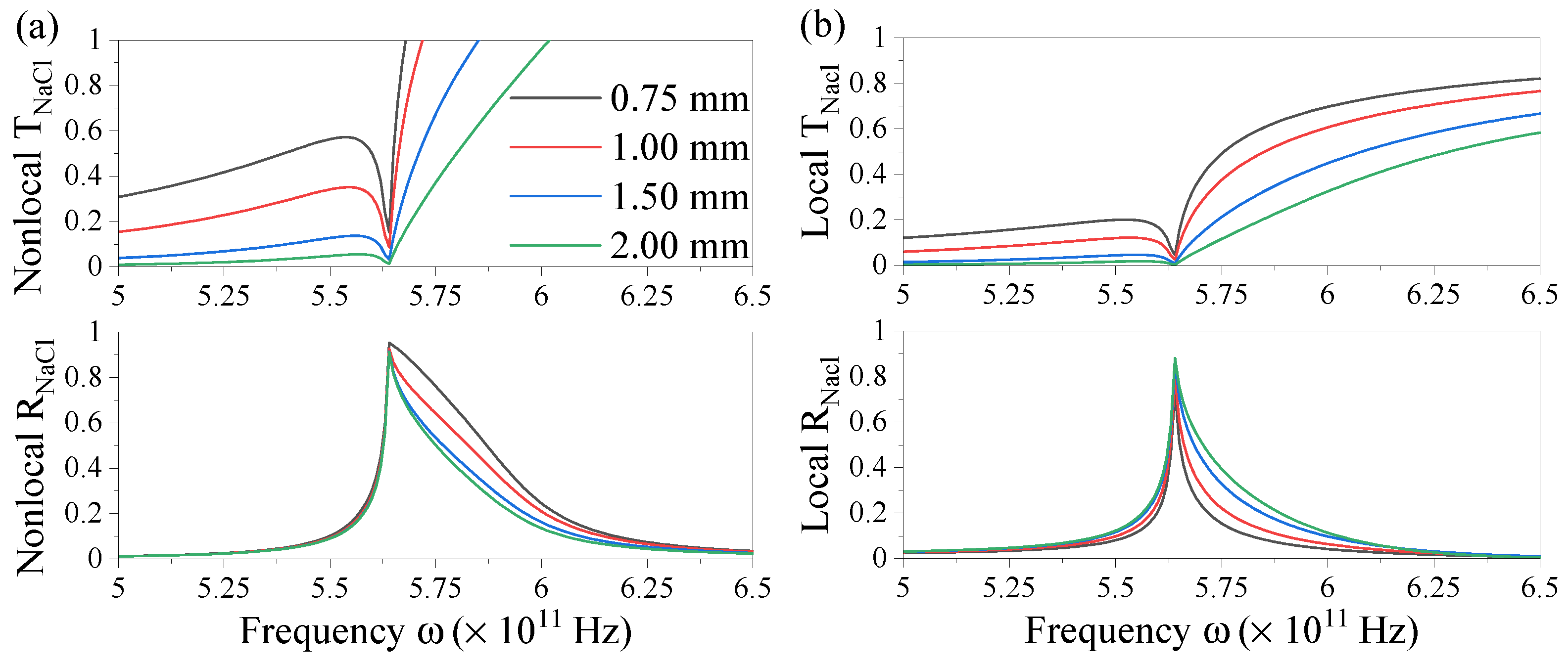
We compare spectra of the fluxes for a nonlocal system in a water-electrolyte-water configuration with its local case in Figure 6 varying the thickness of the electrolyte layer. The highest T is observed for the lowest thickness and vice versa for reflection, which can be expected for the only slightly absorbing material. The reflection peaks become broader for the lower layer thickness where the nonlocal strength increases. Note that the local and nonlocal theories coincide for the case of thickness mm which means that the local limit is reached and the nonlocal interactions no longer alter the optical response. The resonance position is stable and any induced blue shift as observed in solid metal nonlocal systems [25,27,28,30,35,38] is not resolved in this frequency regime. In metal systems, such a shift results in a few tens of nanometers for highly nonlocal systems. In ionic systems, where the resonance wavelength is several orders of magnitude larger, such a shift does not have an impact given the broadening of the peaks with increased nonlocal interaction. As before, the transmitted flux becomes larger than 1 in the evanescent regime past the resonance frequency but reduces to the local result when decreasing the parallel momentum.
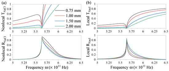
Figure 6.
Transmission (upper panel) and reflection spectra (lower panel) of ionized NaCl in solution in the (a) nonlocal and (b) local case for varying layer thickness d and with parallel momentum m.
4. Conclusions
We studied the nonlocal plasmonic response of planar electrolyte-dielectric interfaces in comparison to the local response approximation of classical electrodynamics. We believe that there is a need to create an understanding of plasmonics beyond electrons in solid matter. Ions are resonant in the far-infrared and are typically confined to mesoscopic length scales in the range of a few hundred microns, e.g., in biological systems separated by thin membranes. Their analytical plasmonic dispersion curve exhibits weak SPPs due to their typically low charge carrier concentration. These fundamental properties arise due to their large mass resulting in low thermal velocities which determines the interaction strengths of the nonlocal charge carrier interaction. Overall, their plasmonic behavior is comparable to electrons in metals. However, they offer a wider range of tunability by choice of material allowing for the adjustment of material mass, charge and concentration.
In addition to studying classical plasmonic properties of ions in a planar electrolyte layer, we use the hydrodynamic two-fluid model to assess spatial dispersion effects in ionic systems. A coupled dynamics of the negative and positive ions is obtained from the analytical expressions of charge densities. In a three-layered system with dielectric-electrolyte interfaces, the complexity is increased by the additional longitudinal modes associated with nonlocal wave numbers . This manifests as resonance broadening of the energy flux. The wave amplitudes of these modes were obtained from the additional boundary condition at the electrolyte-dielectric interfaces. In the limit of the nonlocal analytical expressions, we retrieve the original expressions for the local response.
We conclude from these results that a notable difference in the optical coefficients arises in ionic fluids confined to a planar slab when ion-ion interaction is considered. Our analysis allows for systematically increasing the complexity further to a three-layered multi-fluid ionic system, where the contributions stem from more than two ionic constituents. However, it should be noted that further effects are of importance in solutions with liquid-liquid interfaces even when separated by thin membranes. Firstly, while such membranes offer some stability, the interfaces are constantly shape-shifting and forming a wave pattern instead of an idealized planar surface. Secondly, although the ions cannot move freely due to the confinement, osmosis will take place allowing them to transfer into a neighboring layer and, ultimately, altering the concentration until an equilibrium is reached between a neutral and an ionized layer. Such elaborate aspects are worth investigating in the future. Exploiting the plasmonic properties of ions can open up new avenues in their description and, thus, expand our understanding of their behaviour. We believe that extending plasmonics towards soft matter can bridge soft and hard matter regimes with potential applications in biology and chemistry.
Author Contributions
Conceptualization, C.D.; methodology, C.D.; software, P.R.N.; validation, P.R.N. and C.D.; formal analysis, P.R.N.; writing—original draft preparation, P.R.N.; writing—review and editing, P.R.N. and C.D.; visualization, P.R.N.; funding acquisition, C.D. All authors have read and agreed to the published version of the manuscript.
Funding
We acknowledge financial support by the program ProChancecareer of the Friedrich-Schiller-University Jena (2.11.3-A1/2020-02). This article is the result of P.R.N.’s research project within the framework of the Honours Program for Future Researchers at the Friedrich Schiller University Jena, Germany, funded by the Excellence Strategy of the German State Government and the Länder. The APC was kindly waived for this invited contribution.
Institutional Review Board Statement
Not applicable.
Informed Consent Statement
Not applicable.
Data Availability Statement
The datasets generated and analyzed during the presented study are available upon reasonable request from the corresponding author.
Conflicts of Interest
The authors declare no conflict of interest.
Appendix A. Nonlocal Function Fl±
The function connects the optical coefficients of the longitudinal with the transversal modes Equation (12) and is found after applying the respective boundary conditions and solving the resulting system of linear equations. Its analytic expression is
where , , and are given by
References
- Maier, S.A. Plasmonics: Fundamentals and Applications; Springer: New York, NY, USA, 2007. [Google Scholar] [CrossRef]
- Tang, B.; Guo, Z.; Jin, G. Polarization-controlled and symmetry-dependent multiple plasmon-induced transparency in graphene-based metasurfaces. Opt. Express 2022, 30, 35554–35566. [Google Scholar] [CrossRef] [PubMed]
- Lai, R.; Shi, P.; Yi, Z.; Li, H.; Yi, Y. Triple-Band Surface Plasmon Resonance Metamaterial Absorber Based on Open-Ended Prohibited Sign Type Monolayer Graphene. Micromachines 2023, 14, 953. [Google Scholar] [CrossRef] [PubMed]
- Ye, Z.; Wu, P.; Wang, H.; Jiang, S.; Huang, M.; Lei, D.; Wu, F. Multimode tunable terahertz absorber based on a quarter graphene disk structure. Results Phys. 2023, 48, 106420. [Google Scholar] [CrossRef]
- Chen, Z.; Cai, P.; Wen, Q.; Chen, H.; Tang, Y.; Yi, Z.; Wei, K.; Li, G.; Tang, B.; Yi, Y. Graphene Multi-Frequency Broadband and Ultra-Broadband Terahertz Absorber Based on Surface Plasmon Resonance. Electronics 2023, 12, 2655. [Google Scholar] [CrossRef]
- Schuller, J.A.; Barnard, E.S.; Cai, W.; Jun, Y.C.; White, J.S.; Brongersma, M.L. Plasmonics for extreme light concentration and manipulation. Nat. Mater. 2010, 9, 193–204. [Google Scholar] [CrossRef] [PubMed]
- Luo, Y.; Chamanzar, M.; Adibi, A. Compact on-chip plasmonic light concentration based on a hybrid photonic-plasmonic structure. Opt. Express 2013, 21, 1898. [Google Scholar] [CrossRef] [PubMed]
- Kauranen, M.; Zayats, A.V. Nonlinear plasmonics. Nat. Photonics 2012, 6, 737–748. [Google Scholar] [CrossRef]
- Krasavin Alexey, V.; Pavel, G.; Zayats Anatoly, V. Free-electron Optical Nonlinearities in Plasmonic Nanostructures: A Review of the Hydrodynamic Description. Laser Photonics Rev. 2018, 12, 1700082. [Google Scholar] [CrossRef]
- Mesch, M.; Metzger, B.; Hentschel, M.; Giessen, H. Nonlinear Plasmonic Sensing. Nano Lett. 2016, 16, 3155–3159. [Google Scholar] [CrossRef] [PubMed]
- Beer, S.; Gour, J.; Alberucci, A.; David, C.; Nolte, S.; Zeitner, U.D. Second harmonic generation under doubly resonant lattice plasmon excitation. Opt. Express 2022, 30, 40884. [Google Scholar] [CrossRef]
- Daryakar, N.; David, C. Thin Films of Nonlinear Metallic Amorphous Composites. Nanomaterials 2022, 12, 3359. [Google Scholar] [CrossRef]
- Zhang, C.; Ji, M.; Zhou, X.; Mi, X.; Chen, H.; Zhang, B.; Fu, Z.; Zhang, Z.; Zheng, H. Plasmon-Assisted Self-Encrypted All-Optical Memory. Adv. Funct. Mater. 2022, 33, 2208561. [Google Scholar] [CrossRef]
- Taylor, A.B.; Michaux, P.; Mohsin, A.S.M.; Chon, J.W.M. Electron-beam lithography of plasmonic nanorod arrays for multilayered optical storage. Opt. Express 2014, 22, 13234. [Google Scholar] [CrossRef]
- Green, M.A.; Pillai, S. Harnessing plasmonics for solar cells. Nat. Photonics 2012, 6, 130–132. [Google Scholar] [CrossRef]
- Enrichi, F.; Quandt, A.; Righini, G. Plasmonic enhanced solar cells: Summary of possible strategies and recent results. Renew. Sustain. Energy Rev. 2018, 82, 2433–2439. [Google Scholar] [CrossRef]
- David, C.; Koduvelikulathu, L.J.; Kopecek, R. Comparative Simulations of Conductive Nitrides as Alternative Plasmonic Nanostructures for Solar Cells. Energies 2021, 14, 4236. [Google Scholar] [CrossRef]
- Fusco, Z.; Catchpole, K.; Beck, F.J. Investigation of the mechanisms of plasmon-mediated photocatalysis: Synergistic contribution of near-field and charge transfer effects. J. Mater. Chem. C 2022, 10, 7511–7524. [Google Scholar] [CrossRef]
- Taylor, A.B.; Zijlstra, P. Single-Molecule Plasmon Sensing: Current Status and Future Prospects. ACS Sens. 2017, 2, 1103–1122. [Google Scholar] [CrossRef] [PubMed]
- Zhou, X.L.; Yang, Y.; Wang, S.; Liu, X.W. Surface Plasmon Resonance Microscopy: From Single-Molecule Sensing to Single-Cell Imaging. Angew. Chem. Int. Ed. 2020, 59, 1776–1785. [Google Scholar] [CrossRef] [PubMed]
- Sharma, B.; Frontiera, R.R.; Henry, A.I.; Ringe, E.; Duyne, R.P.V. SERS: Materials, applications, and the future. Mater. Today 2012, 15, 16–25. [Google Scholar] [CrossRef]
- Schlücker, S. Surface-Enhanced Raman Spectroscopy: Concepts and Chemical Applications. Angew. Chem. Int. Ed. 2014, 53, 4756–4795. [Google Scholar] [CrossRef]
- Stockman, M.I.; Kneipp, K.; Bozhevolnyi, S.I.; Saha, S.; Dutta, A.; Ndukaife, J.; Kinsey, N.; Reddy, H.; Guler, U.; Shalaev, V.M.; et al. Roadmap on plasmonics. J. Opt. 2018, 20, 043001. [Google Scholar] [CrossRef]
- Rezaei, S.D.; Dong, Z.; Chan, J.Y.E.; Trisno, J.; Ng, R.J.H.; Ruan, Q.; Qiu, C.W.; Mortensen, N.A.; Yang, J.K. Nanophotonic Structural Colors. ACS Photonics 2020, 8, 18–33. [Google Scholar] [CrossRef]
- García de Abajo, F.J. Nonlocal Effects in the Plasmons of Strongly Interacting Nanoparticles, Dimers, and Waveguides. J. Phys. Chem. C 2008, 112, 17983–17987. [Google Scholar] [CrossRef]
- Scholl, J.A.; Koh, A.L.; Dionne, J.A. Quantum plasmon resonances of individual metallic nanoparticles. Nature 2012, 483, 421–427. [Google Scholar] [CrossRef] [PubMed]
- David, C.; García de Abajo, F.J. Spatial Nonlocality in the Optical Response of Metal Nanoparticles. J. Phys. Chem. C 2011, 115, 19470–19475. [Google Scholar] [CrossRef]
- Raza, S.; Stenger, N.; Kadkhodazadeh, S.; Fischer, S.V.; Kostesha, N.; Jauho, A.P.; Burrows, A.; Wubs, M.; Mortensen, N.A. Blueshift of the surface plasmon resonance in silver nanoparticles studied with EELS. Nanophotonics 2013, 2, 131. [Google Scholar] [CrossRef]
- Raza, S.; Bozhevolnyi, S.I.; Wubs, M.; Mortensen, N.A. Nonlocal optical response in metallic nanostructures. J. Phys. Cond. Matter. 2015, 27, 183204. [Google Scholar] [CrossRef] [PubMed]
- Fernández-Domínguez, A.I.; Wiener, A.; García-Vidal, F.J.; Maier, S.A.; Pendry, J.B. Transformation-Optics Description of Nonlocal Effects in Plasmonic Nanostructures. Phys. Rev. Lett. 2012, 108, 106802. [Google Scholar] [CrossRef] [PubMed]
- Zuloaga, J.; Prodan, E.; Nordlander, P. Quantum Description of the Plasmon Resonances of a Nanoparticle Dimer. Nano Lett. 2009, 9, 887–891. [Google Scholar] [CrossRef] [PubMed]
- Ciracì, C.; Hill, R.T.; Mock, J.J.; Urzhumov, Y.; Fernández-Domínguez, A.I.; Maier, S.A.; Pendry, J.B.; Chilkoti, A.; Smith, D.R. Probing the Ultimate Limits of Plasmonic Enhancement. Science 2012, 337, 1072–1074. [Google Scholar] [CrossRef] [PubMed]
- Toscano, G.; Straubel, J.; Kwiatkowski, A.; Rockstuhl, C.; Evers, F.; Xu, H.; Mortensen, N.A.; Wubs, M. Resonance shifts and spill-out effects in self-consistent hydrodynamic nanoplasmonics. Nat. Commun. 2015, 6, 7132. [Google Scholar] [CrossRef] [PubMed]
- Zhu, W.; Esteban, R.; Borisov, A.G.; Baumberg, J.J.; Nordlander, P.; Lezec, H.J.; Aizpurua, J.; Crozier, K.B. Quantum mechanical effects in plasmonic structures with subnanometre gaps. Nat. Commun. 2016, 7, 11495. [Google Scholar] [CrossRef] [PubMed]
- Wiener, A.; Fernández-Domínguez, A.I.; Horsfield, A.P.; Pendry, J.B.; Maier, S.A. Nonlocal Effects in the Nanofocusing Performance of Plasmonic Tips. Nano Lett. 2012, 12, 3308–3314. [Google Scholar] [CrossRef]
- David, C.; Christensen, J.; Mortensen, N.A. Spatial dispersion in two-dimensional plasmonic crystals: Large blueshifts promoted by diffraction anomalies. Phys. Rev. B 2016, 94, 165410. [Google Scholar] [CrossRef]
- Mortensen, N.A.; Raza, S.; Wubs, M.; Søndergaard, T.; Bozhevolnyi, S.I. A generalized non-local optical response theory for plasmonic nanostructures. Nat. Commun. 2014, 5, 3809. [Google Scholar] [CrossRef] [PubMed]
- Raza, S.; Wubs, M.; Bozhevolnyi, S.I.; Mortensen, N.A. Nonlocal study of ultimate plasmon hybridization. Opt. Lett. 2015, 40, 839–842. [Google Scholar] [CrossRef] [PubMed]
- Mortensen, N.A. Mesoscopic electrodynamics at metal surfaces. Nanophotonics 2021, 10, 2563–2616. [Google Scholar] [CrossRef]
- Kolle, M.; Lee, S. Progress and Opportunities in Soft Photonics and Biologically Inspired Optics. Adv. Mater. 2017, 30, 1702669. [Google Scholar] [CrossRef]
- van der Gucht, J. Grand Challenges in Soft Matter Physics. Front. Phys. 2018, 6, 87. [Google Scholar] [CrossRef]
- Jacak, J.; Jacak, W. Plasmons and Plasmon–Polaritons in Finite Ionic Systems: Toward Soft-Plasmonics of Confined Electrolyte Structures. Appl. Sci. 2019, 9, 1159. [Google Scholar] [CrossRef]
- Jacak, W.A. Plasmons in finite spherical electrolyte systems: RPA effective jellium model for ionic plasma excitations. Plasmonics 2016, 11, 637–651. [Google Scholar] [CrossRef] [PubMed]
- David, C. Two-fluid, hydrodynamic model for spherical electrolyte systems. Sci. Rep. 2018, 8, 7544. [Google Scholar] [CrossRef] [PubMed]
- Maack, J.R.; Mortensen, N.A.; Wubs, M. Size-dependent nonlocal effects in plasmonic semiconductor particles. EPL (Europhys. Lett.) 2017, 119, 17003. [Google Scholar] [CrossRef]
- Maack, J.R.; Mortensen, N.A.; Wubs, M. Two-fluid hydrodynamic model for semiconductors. Phys. Rev. B 2018, 97, 115415. [Google Scholar] [CrossRef]
- Dong, T.; Yin, K.; Gao, X.; Ma, X. Generalized local analogue model for nonlocal plasmonic nanostructures based on multiple-fluid hydrodynamic framework. J. Phys. Appl. Phys. 2020, 53, 295105. [Google Scholar] [CrossRef]
- Jacak, J.E.; Jacak, W.A. New wave-type mechanism of saltatory conduction in myelinated axons and micro-saltatory conduction in C fibres. Eur. Biophys. J. 2020, 49, 343–360. [Google Scholar] [CrossRef] [PubMed]
- Jacak, J.E.; Jacak, W.A. Explanation of saltatory conduction in myelinated axons and of micro-saltatory conduction in C fibers of pain sensation by a wave-type ion plasmonic mechanism of stimulus kinetics. bioRxiv 2023. [Google Scholar] [CrossRef]
- Johnson, P.B.; Christy, R.W. Optical Constants of noble metals. Phys. Rev. B 1972, 6, 4370–4379. [Google Scholar] [CrossRef]
- Kluczyk, K.; Jacak, L.; Jacak, W.; David, C. Microscopic Electron Dynamics in Metal Nanoparticles for Photovoltaic Systems. Materials 2018, 11, 1077. [Google Scholar] [CrossRef]
- Toscano, G.; Raza, S.; Jauho, A.P.; Mortensen, N.A.; Wubs, M. Modified field enhancement and extinction by plasmonic nanowire dimers due to nonlocal response. Opt. Express 2012, 20, 4176–4188. [Google Scholar] [CrossRef] [PubMed]
- David, C.; García de Abajo, F.J. Surface Plasmon Dependence on the Electron Density Profile at Metal Surfaces. ACS Nano 2014, 8, 9558–9566. [Google Scholar] [CrossRef] [PubMed]

Disclaimer/Publisher’s Note: The statements, opinions and data contained in all publications are solely those of the individual author(s) and contributor(s) and not of MDPI and/or the editor(s). MDPI and/or the editor(s) disclaim responsibility for any injury to people or property resulting from any ideas, methods, instructions or products referred to in the content. |
© 2023 by the authors. Licensee MDPI, Basel, Switzerland. This article is an open access article distributed under the terms and conditions of the Creative Commons Attribution (CC BY) license (https://creativecommons.org/licenses/by/4.0/).