Article

AR-HUD Optical System Design and Its Multiple Configurations Analysis

Guangxi Key Laboratory of Optoelectronic Information Processing, School of Optoelectronic Engineering, Guilin University of Electronic Technology, Guilin 541004, China
*
Author to whom correspondence should be addressed.
Photonics 2023, 10(9), 954; https://doi.org/10.3390/photonics10090954
Submission received: 8 June 2023 / Revised: 3 August 2023 / Accepted: 14 August 2023 / Published: 22 August 2023
(This article belongs to the Special Issue Advances in Photonic Materials and Technologies)

Abstract

:
The use of augmented reality head-up displays (AR-HUD) in automobile safety driving has drawn more and more interest in recent years. An AR-HUD display system should be developed to fit the vehicle and the complicated traffic environment in order to increase the driver’s driving concentration and improve the man–vehicle synchronization. In this article, we suggest an AR-HUD display system with dual-layer virtual-image displays for the near field and far field, as well as further research and design of the adjustment system for multi-depth displays of far-field images. It also examines the EYEBOX horizontal adjustment margin of the dual light path. The analysis results show that the scale of EYEBOX is 120 × 60 mm2, the modulation transfer function (MTF) of near-field light path > 0.2 @ 6.7 lp/mm, and the MTF of far-field optical path > 0.4 @ 6.7 lp/mm. The distortion of the near-field optical path is less than 0.86%, and that of the far-field optical path is less than 2.2%. By modifying the folding mirror, the far-field optical path creates an 8 m to 24 m multi-depth virtual picture display. Image quality can be maintained when the near-field and far-field optical paths are moved horizontally by 25 mm and 100 mm, respectively. This study offers guidelines for the multi-depth display, EYEBOX horizontal adjustment, and optical layout of augmented reality head-up displays.

1. Introduction

Head-up display (HUD) is a display technology based on vehicle–machine interactions that reflects vehicle driving information into the human eye through optical components so that the driver can read the information in a horizontal view to improve driving safety, such as speed, fuel consumption, navigation information, driver assistance information, warning information, etc. The first use of HUD was in the 1950s, for aiming and shooting [1]. In 1960, the Hawker Siddeley Buccaneer first used heads-up display technology in military aircraft [2]. HUD was first deployed in commercial aviation in 1970 [3]. In 1988, HUD technology was initially made available in Oldsmobile and Pontiac models by General Motors (GM) [4]. At present, the Boeing 787 Dreamliner is the first mainstream commercial aircraft to use HUD as the standard model [5]. The benefit of HUD is that it allows the driver to avoid moving between the flat (0–5°) road conditions and the overhead (20–25°) dashboard, which eliminates the need for constant switching between dark and light settings. The threshold for traffic accidents is taking one’s eyes off the road for longer than two seconds, which is a primary contributor to traffic accidents [6]. Equipped with HUD, system drivers can read vehicle driving information in a flat perspective, especially to reduce the risk of traffic accidents for senior drivers, enhance driving coordination, and improve man–machine efficiency.
Combiner HUD (C-HUD), Windshield HUD (W-HUD), and Augmented Reality HUD (AR-HUD) are some of the existing head-up display systems for cars. W-HUD and AR-HUD both reflect the image source into the driver’s eyes through the front windshield, and AR-HUD can be seen as an upgraded version of W-HUD. Rear-mounted HUDs like the C-HUD, which also includes instrument panel and suspension types, pose a safety risk to drivers in the event of an accident. Front-mounted embedded HUD including such image generation units (PGUs), flat reflector, freeform reflector, wedge-shaped front windscreen, etc., are called W-HUD and AR-HUD. W-HUD is the primary HUD product at the moment, with virtual image dimensions of 7~12 inches, a field of view (FOV) of fewer than 10 degrees, and a virtual image distance (VID) of 1.8~2.5 m. The inevitable trend of HUD development is toward AR-HUD, which has a VID of more than 7 m, a FOV of more than 10°, and a larger virtual image size. It can display information from advanced driver assistance systems and realize true human, vehicle, and road collaboration [7,8]. The global installed base of HUDs will reach 15 million units in 2025, with W-HUD serving as the primary product, and close to 35 million units in 2030, with AR-share HUD’s expanding quickly, according to Continental’s head-up display market development forecast data [9].
According to the type of imaging, current AR-HUD optical systems can be divided into two categories: geometric optical imaging and physical optical imaging. Geometric optical imaging include the author-designed off-axis three-mirror HUD optical system, where the PGU, plane mirror, and freeform reflector were laid out in the same horizontal plane [10,11,12]. By using Solidworks’ basic mechanical assembly structure to determine the coordinates of the plane mirror and PGU, the light constraint equations were developed to guarantee unhindered light transmission [11]. The study could not have an augmented reality influence on the Advanced Driving Assistance System information that should have been given in the far-field optical path because it was only designed and analyzed for the near-field light path. To accomplish infinity imaging with a FOV of 24° × 15°, the authors created an off-axis quad-mirror HUD optical system for airplanes [12]. The initial spatial architecture of the four-mirror system was acquired by restricting the edge beam of the maximum FOV. In the end, the biological lens parallax was assessed and adjusted to produce infinity imaging with a FOV of 24° × 15°. The design of this aircraft head-up display system is only designed and analyzed for the virtual image at infinity, which does not have the effect of layered display. Using lens eccentricity and tilt to correct for the aberrations and off-axis aberrations caused by the asymmetric FOV and the tilted and bent combiner, physical optical imaging researchers like the authors designed a holographic HUD optical system with an asymmetric large FOV [13,14,15,16]. However, physical optical imaging technology is still in its infancy and cannot currently handle the demand for batch use. Other AR-HUD optical systems exist that use two PGUs and a dual optical route separation design method, but these systems require more room to install. At the same time, we have yet to see an AR-HUD system that performs a continuous multi-depth display with a large range of far-field light paths, which will not maximize the augmented reality effect of the AR system. Therefore, it is essential to suggest a new AR-HUD optical system with dual-layer display functionality that uses a coupling architecture of near-field and far-field dual optical routes. Based on this, the optimum augmented reality impact requires its far-field optical channel to have a wide range of continuous multi-depth virtual image display capabilities. This article is devoted to exploring this problem.
In this paper, we develop a single PGU approach for linking near-field and far-field dual optical routes in order to solve the issue of huge space occupation while designing near-field and far-field split optical channels with dual PGUs for AR-HUD [13,14]. The design difference of the upper and lower FOV deviation allows the near-field and far-field dual optical paths to deviate in position on the free surface reflector, while the far-field optical path is connected to the common image plane by a folding mirror and the near-field optical path. The optical distortion of the near and far field is less than 0.86% and 2.2%, respectively, and this design achieves an MTF of the near-field optical path > 0.2 @ 6.7 lp/mm and an MTF of the far-field optical path > 0.4 @ 6.7 lp/mm. The spot diagrams of the near- and far-field light paths are also within the Airy disk. In addition, taking into account the requirement for far-field image distance in various road scenes, a design analysis for a multi-depth variable VID for far-field images from 8 to 24 m was carried out. This design analysis shows that the requirement for the multi-depth virtual image quality can be met only by adjusting the distance of three folding mirrors, while also guaranteeing the constant PGU position at various VIDs. It was discovered that there was no appreciable loss of image quality when the near-field optical path was adjusted horizontally by 25 mm in the preset EYEBOX plane and by 100 mm in the far-field optical path in the preset EYEBOX plane within the EYEBOX horizontal adjustment range (120 × 60 mm2) in the near-field and far-field optical paths.

2. Optical Design

2.1. Design Considerations and System Parameters

The AR-HUD optical system consists of two optical routes: near field and far field, with the single PGU scheme and the double PGUs scheme being used for the two optical paths, respectively. The single PGU scheme divides a projection screen into near-field and far-field sections and creates two virtual images of various sizes and distances through two optical paths. This method has clear volumetric advantages and is the current development trend for AR-HUD systems. From the virtual image end to the human eye, then to the windshield, freeform reflector, folding mirror, and PGU, the AR-HUD optical path system uses an inverse optical path design. The AR-HUD optical route is intended to generate virtual images of various horizontal distances through various object distance settings and virtual images of various vertical heights through various up and down viewing angles. The windshield 3D model can be used to fit the optical surface shape, and an optical reflection model can be built. Different models’ data for the windshield surface and inclination angle varies slightly. The design does the design analysis at a 45° tilt angle condition and cites the windshield face pattern data from the study [17]. As an off-axis, unobstructed reflective optical system, the HUD introduces a number of aberrations like a spherical aberration, coma, astigmatism, field curvature, distortion, etc., due to the system architecture and hyperbolic features of the windshield glass surface. When designing an aberration, balance and correction are accomplished using a freeform reflector with strong aberration correction capability. Zernike polynomial and Seidel aberration have a direct mapping relationship that allows for the effective and individual correction of each aberration while also allowing for the conversion to a more processing-friendly XY polynomial surface type. The design of the freeform reflector uses the Zernike standard sag surface type. The Zernike Standard Sag surface is defined by the same polynomial as the Even Aspheric surface (which supports planes, spheres, conics, and polynomial aspheres) plus additional aspheric terms defined by the Zernike Standard coefficients. The surface sag is of the form:
z = c r 2 1 + 1 1 + k c 2 r 2 + i = 1 8 α i r 2 i + i = 1 N A i Z i ρ , φ
where c denotes the basal curvature, k is the aspheric coefficient, r is the radial ray coordinate in lens units, αi is the coefficient on the ith Even Aspheric polynomial, N is the number of Zernike coefficients in the series, Ai is the coefficient on the ith Zernike Standard polynomial, ρ is the normalized radial ray coordinate, and φ is the angular ray coordinate.
The cut-off frequency of the modulation transfer function (MTF), which corresponds to the PGU pixel size of 75 μm in the design, is 6.7 lp/mm. The driver’s EYEBOX, which is where their eyes are focused when they are operating a vehicle, is where the virtual image that PGU projects may be seen. Its front and back depth can be adjusted, and its design size is 120 × 60 mm2. The preset distance of far-field virtual image is not less than 7 m, the FOV is not less than 10°, the distance of near-field image is around 2 m, and the FOV is not less than 6°. The authors used two freeform reflectors to design an AR-HUD optical system including only the far-field optical path, with a horizontal FOV of 10° and a vertical FOV of 5° [8]. The authors used freeform reflector to design an AR system including only the near-field optical path, with a horizontal FOV of 5° and a vertical FOV of 2.5° [11]. This study suggests designing a dual-field AR-HUD optical system with a 6° × 2° FOV for the near-field optical path and a 10° × 3° FOV for the far-field optical path, taking into account the challenge of dual-optical path coupling design and the upper and lower viewing angle deviation of the near-field and far-field optical paths. The design indexes of AR-HUD optical system are shown in Table 1.

2.2. Optical Layout and Design Methods

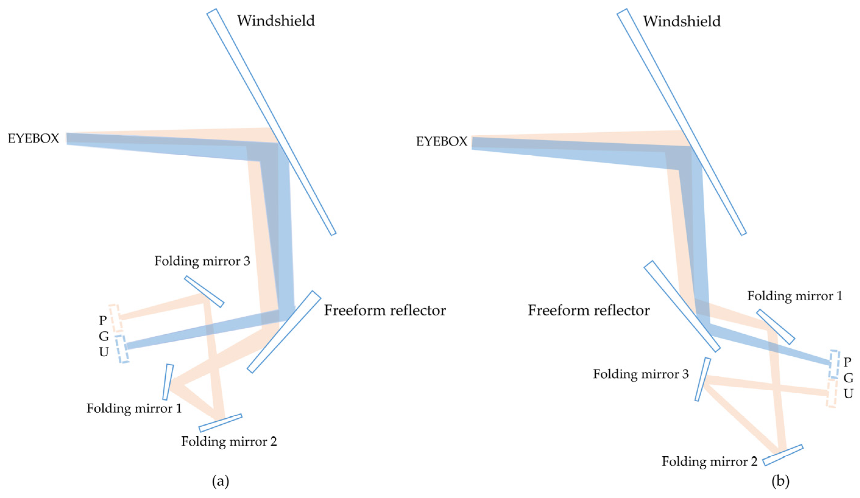
2.2.1. Two Possible Optical Layouts

The fully reflective optical system, which has flexible design forms and fewer optical components than the conventional refractive optical system, does not cause chromatic aberration and is suitable for broad-spectrum and multispectral imaging, especially for large FOV and large aperture optical system design. Due to the fact that off-axis characteristics still necessitate up- and down-view deviations for AR-HUD near-field and far-field optical routes, freeform reflectors may provide two optical layouts, as shown in Figure 1a,b, depending on the reflectors’ placement angles. Three folding mirrors fold the far-field optical path and connect it to a shared image plane with the near-field optical path, providing an adjustment margin to maintain the image plane position constant throughout the ensuing 8~24 m continuous multi-depth virtual image adjustment.

2.2.2. Design Method

The optical arrangement of the dual optical channel is one of the challenges in the original design of the AR-HUD optical system. Several simulations were used to tweak the design to obtain the two optical configurations shown in Figure 1. The optical arrangement in Figure 1a produces the effect of multiple mirrors without blocking and dual optical routes with a common image plane. The design and analysis work of this study is focused on this optical layout. The coupling of the dual optical routes’ initial structures must be realized via ZEMAX’s multi-configuration function since the two optical paths’ fields of view, VIDs, and upper and lower viewing angles are all out of alignment. The freeform reflector is shared by the two optical pathways, and because the near-field optical path is relatively straightforward and heavily dependent on the placement angle of the freeform reflector, the priority design of the near-field optical path can be taken into account. By repositioning several mirrors to create a double optical route without blocking coupling, the far-field optical way is based on the near-field optical path, and the multi-stage folding mirror is optimized to meet the requirements of the far-field optical path design. The radius of curvature, rotation angle, and distance of each reflector, as well as the image plane coupling of the two optical channels, are the parameters that must be constrained during the design process.
Although the design process should consider the F-number of the near-field and far-field optical paths, the design should be optimized using the full aperture of 134 mm. However, the image quality is evaluated for the size of the human eye pupil, considering the human eye pupil maximum. The system F-number will increase 16.75 times in the case of 8 mm. Using the diffraction limit equation as a guide [18]:
Δ θ = 1.22 λ / D
where Δθ is the minimum resolution angle of the optical system, λ is the wavelength, and D is the pupil diameter. When Δθ is very small, sinΔθ ≈ Δθ, which is approximately equal to D/f, D is the minimum resolution size, and f is the focal length, we can obtain:
f / D = d / 1.22 λ
The diffraction limit aperture is 104.7 when the center wavelength is 0.587 um and the image element size is 75 μm. Consequently, when maximizing for an optical system with a human eye pupil of 8 mm at a full aperture of 134 mm, the system F-number should be close to 6.3 or even lower.

2.2.3. Design Results and Analysis

The varied amounts of aberrations in the dual optical routes are corrected after the synergistic optimization design of the near-field and far-field optical paths, and the superior image quality design under the dual structure is obtained. Figure 2 displays the outcomes of the dual optical route design, with the near-field optical path illustrated in green and the far-field optical path shown in blue. A freeform reflector and folding reflector are both present in the blue box. The far-field optical path likewise has two spherical foldable mirrors and one aspheric foldable mirror, and the two optical channels share a freeform reflector. The entire EYEBOX domain can use the design results because the design procedure adopts a 134 mm pupil diameter. The human eye’s pupil can grow to 8 mm in diameter in complete darkness, and the optical system exhibits significant aberration. The visual quality that the human eye sees in these circumstances is suitable for situations with smaller pupils.
The near-field and far-field MTF curves are depicted in Figure 3a,b, respectively, with the spatial frequency acting as the horizontal coordinate and the value of the diffraction modulation transfer function acting as the vertical coordinate. The MTF at the Nyquist frequency of 6.7 lp/mm is greater than 0.2 in the virtual image range of 210 × 70 mm2 for the near-field optical path and is greater than 0.4 in the virtual image range of 1400 × 420 mm2 for the far-field optical path. The imaging quality of the dual optical path is excellent. The image quality of the near-field optical path did not change significantly when the image plane moved in the range of about ±3 mm, and the image quality of the far-field optical path did not change significantly when image plane moved in the range of about ±10 mm. The optical system’s depth of focus is also larger, and the axial adjustment margin of the PGU projection screen is larger, as shown in Figure 4′s MTF out-of-focus curve. Figure 5a,b depict the spot diagrams of the near-field and far-field optical paths, respectively. F1~F9 correspond to the spot diagrams of nine FOV points. The near-field optical path Airy spot’s radius is 83.55 μm larger than its maximum RMS radius of 58.752 μm, and the far-field optical path Airy spot’s radius is 71.26 μm larger than its maximum RMS radius of 16.631μm, indicating that the dual optical path imaging resolution reaches the diffraction limit.
The near-field and far-field optical routes have optical distortions that are less than 0.86% and 2.2%, respectively. Figure 6a,b illustrate the grid distortion effect, where the horizontal and vertical coordinates stand in for the horizontal FOV and the vertical FOV, respectively. The actual images have a slight distortion effect in comparison to the ideal image, but this does not affect how the images are used. The human eye’s pupil distance is 65 mm, so when two people are observing the same object, there will be a parallax between their two eyes. Figure 7 displays the binocular parallax of the 2 m near-field image system and the 8 m far-field image system. As shown in Figure 7a, the near-field system’s binocular divergence parallax is less than 1 mrad and its convergence parallax is less than 2 mrad. As shown in Figure 7b, the far-field system’s binocular divergence parallax is around 1.5 mrad and its convergence parallax is less than 2 mrad, which meets the standard value of clause 4.2.10 in SAE AS8055 [19]. It avoids the physiological discomfort caused by binocular parallax when observing images.

3. Multi-Structure Design Analysis

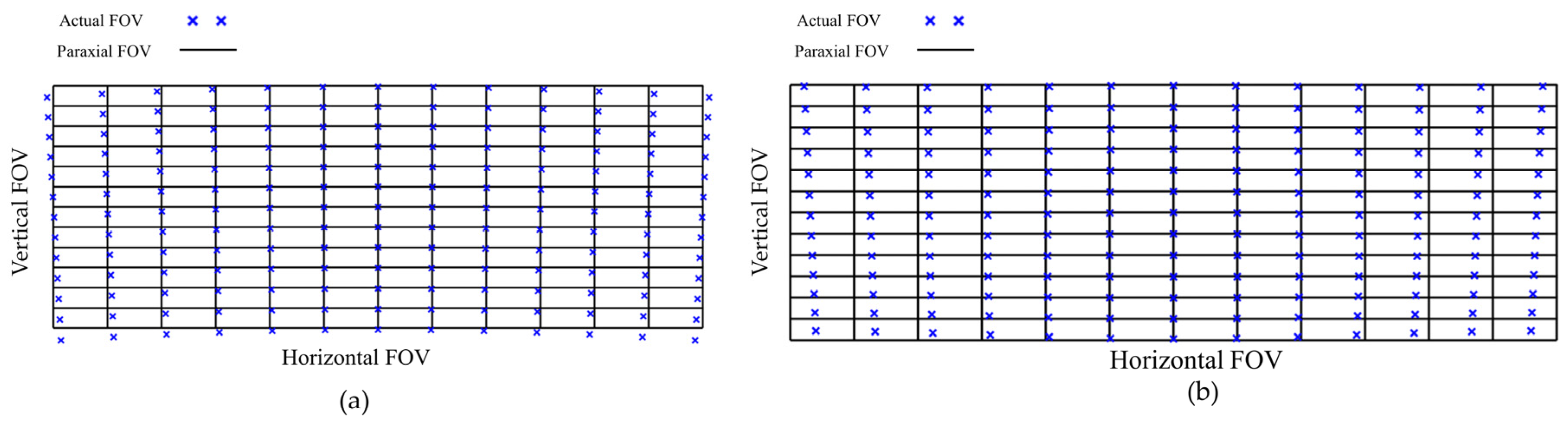
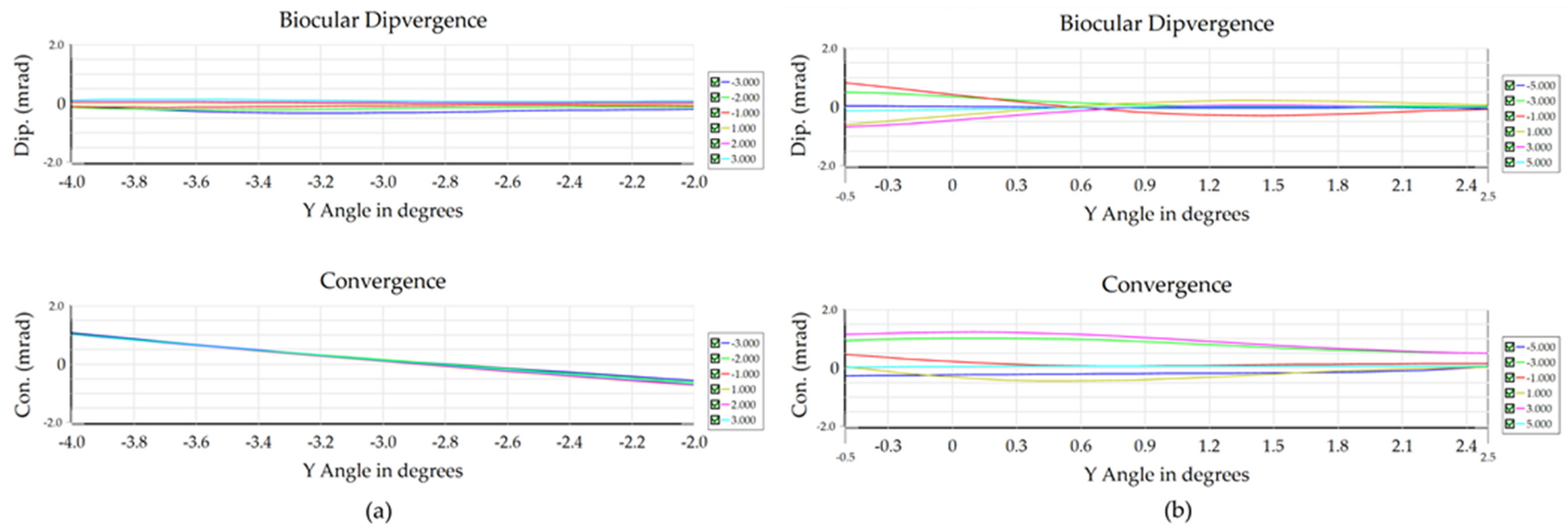
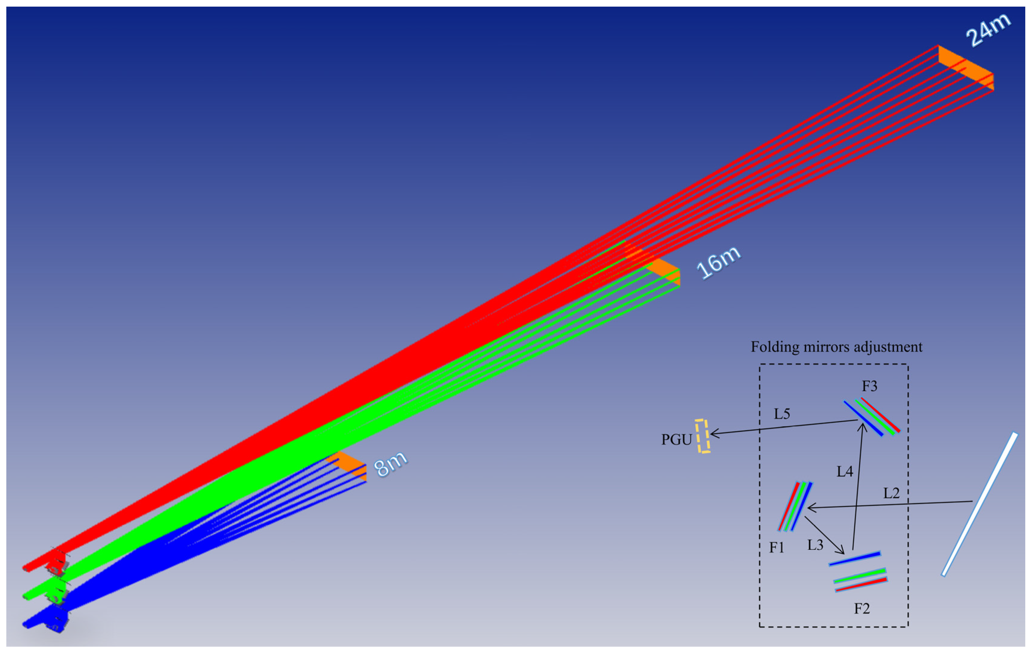
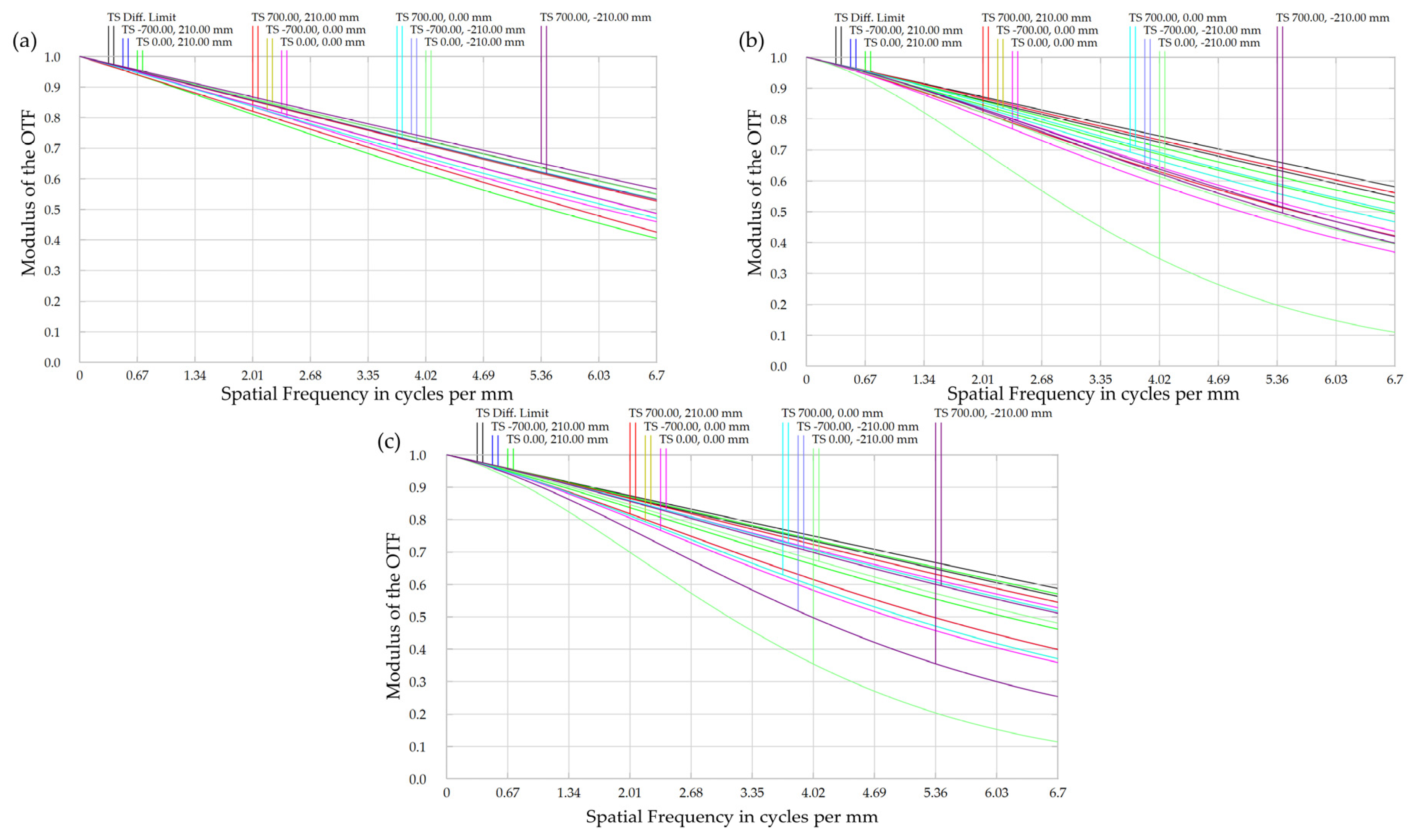
3.1. Multi-Structure Analysis of Far-Field Image

For better augmented reality, the AR-HUD far-field virtual image must be merged with markers placed across the real world at various distances, which suggests that the far-field virtual image is multi-depth adjustable. Two mirrors—a zoom mirror and a compensating mirror—make up the reflective zoom optical system. It is challenging to implement zoom in AR-HUD since it takes up a lot of room and is tough to design. The review mentions a variety of multi-focus display methods, and similarly, the design creates a multi-depth virtual image display by modifying the optics of configuration 2 under the prototype of AR-HUD geometric imaging [20]. With reference to the coaxial zoom optical system, the zooming process maintains the size of the image plane by flipping the field-of-view and focal distance, as well as coordinating the change in image distance. In this case, a smaller field-of-view, a larger VID, and coordinated focal distance change can be used to maintain the size of the virtual image plane. The center coordinates of the PGU image plane are constrained by the design optimization process to remain constant, and multi-depth virtual image distribution is only achieved by adjusting the total 4 distances (L2–L5) of the freeform reflector–folding mirror 1 (F1)–folding mirror 2 (F2)–folding mirror 3 (F3)–image plane. To achieve unhindered light during the adjustment under this optical structure, the distance L2 should rise as the VID increases. Throughout the design phase, the distance L2 is provided as an empirical number, along with the optimized distances L3, L4, and L5. Figure 8 depicts the isometric perspective, and Table 2 displays the specifications of the multi-depth virtual image system.
The coordinated shift in focal length makes optical design less challenging, and the decrease in FOV is accompanied by a decrease in the size of the PGU image and an increase in optical magnification. The design ensures that the fundamental position of the center of the PGU picture plane remains intact while allowing for an increase in VID by altering the distance between folding mirrors (EYEBOX plane is the global coordinate reference plane). Using samples for three depths of 8 m, 16 m, and 24 m, the design achieves continuous depth adjustment of the virtual picture from 8 m to 24 m. The three colors correspond to the positions of the folding mirror at three image depths, as shown in the adjustment schematic for the folding mirror at three virtual image depths in the bottom right of Figure 8. As seen in Figure 9, where Figure 9a depicts the MTF curve for the first sample depth (8 m) as well as the far-field optical path in Section 2.2.3. The MTF curves for the second sampling depth (16 m) and third sampling depth (24 m), respectively, are shown in Figure 9b,c. It can be seen that the MTF values of each FOV at the second and third sampling depths are slightly decreased by the adjustment of the three reflective elements. However, the overall image quality is still excellent and has little impact on how the virtual image is commonly used. In the actual use of the PGU far-field projection screen should be added to the frame scaling function, in order to match the PGU frame reduction characteristics generated by the variable VIDs of the system.

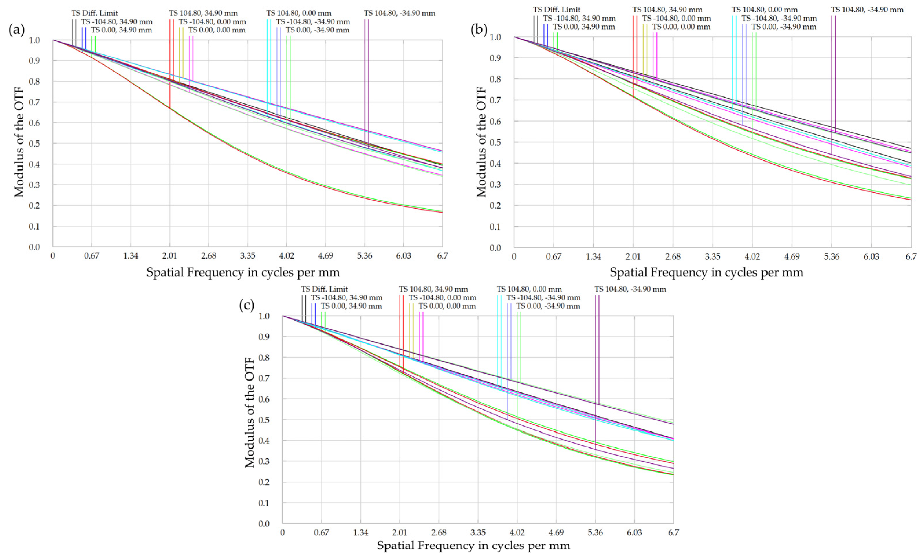
3.2. EYEBOX Multiple Structure Analysis

The intended AR-HUD optical system EYEBOX is at a 900 mm distance from the front windshield; nevertheless, during real use, the driver will adjust their head slightly back and forth, which will interfere somewhat with their ability to observe the virtual image. In the system design of the retro-optical path, it is equivalent to the impact of the micro-adjustment changes in the spatial distance of the object on the image quality of the PGU image plane. Section 2 conducted a coupling design analysis on the close range and distant dual optical paths, which involved many variables. On the basis of Section 2, Section 3.1 implements the multi-depth virtual image analysis of the prospective light path only by adjusting the distance of the folding mirror. Only the EYEBOX horizontal adjustment margin of the near-field and far-field light path created by ZEMAX’s multi-configuration functional analysis will be employed in this case because other optical components were not optimized. On the basis of Section 2, the distance between configuration 1 and configuration 2’s EYEBOX surfaces was changed in a triple structure, and the EYEBOX placements were discovered to have a negligible impact on the quality of the images. The EYEBOX surface with one step added or deleted for analysis is represented by the level 1 and level −1 structures in Figure 10, whereas the level 0 structure reflects the distance already designed in the previous section. Among them, the step size for configuration 1 is 25 mm, and the step size for configuration 2 is 100 mm.
Figure 11 shows the MTF curves of the near-field optical path under the three-level EYEBOX structures of 925 mm, 900 mm, and 875 mm. Among them, Figure 11b (level 0) is the MTF curve of the near-field optical path in 2.2.3, and Figure 11a,c show the MTF curves of the near-field optical path for increasing and decreasing the EYEBOX distance by 25 mm, respectively. The full-field MTF value of the level 1 EYEBOX structure is greater than 0.17 @ 6.7 lp/mm. The full-field MTF value of level −1 EYEBOX structure is better than 2.1 @ 6.7 lp/mm. It is known that the near-field optical path with a ±25 mm horizontal distance adjustment based on the default EYEBOX surface (level 0) has little to no impact on the virtual image’s quality. Figure 12b (level 0) depicts the MTF curve for the far-field optical path in Section 2.2.3, whereas Figure 12a,c depict the MTF curves for the far-field optical path by altering the EYEBOX distance by 100 mm, respectively. The full-field MTF value of the level 1 EYEBOX structure is greater than 0.35 @ 6.7 lp/mm. The full-field MTF value of level −1 EYEBOX structure is better than 0.42 @ 6.7 lp/mm. On the basis of the predetermined EYEBOX surface (level 0), it can be seen that the far-field light path is modified horizontally by ±100 mm, however, the quality of the virtual image will not vary greatly.

4. Conclusions

The prior concepts of single optical path design for near-field HUDs and far-field AR-HUDs are integrated in this study to create a dual optical path coupled adjustable AR-HUD optical system. To actualize the categorized display of in-vehicle information at 2 m and 8 m, a single PGU is separated into near-field and far-field display zones, with the far-field optical route being relayed using the folding mirrors. Only the axial movement of the three folding mirrors is required to show the ADAS information and navigation information of the far-field optical path at any distance between 8 m and 24 m. Therefore, this AR-HUD has the following three advantages: dual optical paths for near-field and far-field categorized information display; the design method of single PGU improves the efficiency of space usage; and the wide range adjustable display of far-field optical path plays a better augmented reality effect. This design concept is conducive to building a multi-dimensional man–machine interaction bridge and promoting the development of automotive intelligent cockpit. In the future, AR-HUD still has room for improvement in terms of display range, space efficiency, and projection source heat dissipation, in order to improve driving safety and man–machine efficiency.

Author Contributions

Conceptualization, Q.J. and Z.G.; methodology, Q.J.; software, Z.G.; validation, Z.G.; investigation, Z.G.; resources, Q.J.; data curation, Z.G.; writing—original draft preparation, Z.G.; writing—review and editing, Q.J. All authors have read and agreed to the published version of the manuscript.

Funding

This research was funded by the National Natural Science Foundation of China (No. 61965005), the Guangxi Key R&D Program (No. Guike AB22035047), and Director Fund Project of Guangxi Key Laboratory of Optoelectronic Information Processing (No. GD21101).

Institutional Review Board Statement

Not applicable.

Informed Consent Statement

Not applicable.

Data Availability Statement

The data are not publicly available due to further study.

Conflicts of Interest

The authors declare no conflict of interest.

References

  1. Crawford, J.; Neal, A. A Review of the Perceptual and Cognitive Issues Associated with the Use of Head-up Displays in Commercial Aviation. Int. J. Aviat. Psychol. 2006, 16, 1–19. [Google Scholar] [CrossRef]
  2. The Emergency Lane: The History of the Head-Up Display. Available online: http://techzle.com/the-emergency-lane-the-history-of-the-head-up-display (accessed on 31 May 2023).
  3. Cho, W.H.; Chao, T.L.; Chi, C.K.; Liao, B.; Lee, C.C. A Novel Head-up Display Using Inclined Al2O3 Column Array. In Proceedings of the Optical Interference Coatings 2013, Whistler, BC, Canada, 16–21 June 2013. [Google Scholar]
  4. Smith, S.; Fu, S.H. The relationships between automobile head-up display presentation images and drivers’ Kansei. Displays 2011, 32, 58–68. [Google Scholar] [CrossRef]
  5. Norris, G. Boeing 787 Dreamliner: Flying Redefined; Aerospace Technical Publications International: Charlotte, NC, USA, 2005. [Google Scholar]
  6. Kim, S.; Dey, A.K. Simulated augmented reality windshield display as a cognitive mapping aid for elder driver navigation. In Proceedings of the 27th International Conference on Human Factors in Computing Systems, CHI 2009, Boston, MA, USA, 4–9 April 2009. [Google Scholar]
  7. China Head Up Display Industry Report C-HUD, W-HUD and AR-HUD. Available online: https://www.renrendoc.com/paper/127055129.html (accessed on 1 June 2023).
  8. Cao, Y. Optimization Design of Optical Module for Vehicle Head Up Display System. Master’s Thesis, Xi’an Technological University, Xi’an, China, 2022. [Google Scholar]
  9. Special Report on Automotive Intelligent Cabin: Core Entry of Incremental Value in the Intelligent Era. Available online: https://baijiahao.baidu.com/s?id=1691543015962744512&wfr=spider&for=pc (accessed on 2 June 2023).
  10. Kim, B.H.; Park, S.C. Optical System Design for a Head-up Display Using Aberration Analysis of an Off-axis Two-mirror System. J. Opt. Soc. Korea 2016, 20, 481–487. [Google Scholar] [CrossRef]
  11. Wei, S.L.; Fan, Z.C.; Zhu, Z.B.; Ma, D.L. Design of a head-up display based on freeform reflective systems for automotive applications. Appl. Opt. 2019, 58, 1675–1681. [Google Scholar] [CrossRef] [PubMed]
  12. Gu, L.; Cheng, D.W.; Liu, Y.; Ni, J.H.; Wang, Y.T. Design and fabrication of an off-axis four-mirror system for head-up display. Appl. Opt. 2020, 59, 4893–4900. [Google Scholar] [CrossRef] [PubMed]
  13. Lee, S.H.; Bang, K.; Lee, B. Design Method of Holographic Mirror and Freeform Mirror for Automotive Augmented Reality Head-up Display. In Proceedings of the OSA Optical Sensors and Sensing Congress 2021 (AIS, FTS, HISE, SENSORS, ES), Seoul, Republic of Korea, 1 January 2021. [Google Scholar]
  14. Blanche, P.; Draper, C.T. Curved Holographic Waveguide Combiner for HUD and AR Display. In Proceedings of the OSA Imaging and Applied Optics Congress 2021 (3D, COSI, DH, ISA, pcAOP), Washington, DC, USA, 19 July 2021. [Google Scholar]
  15. Isomae, Y.; Shibata, Y.; Ishinabe, T.; Fujikake, H. Phase-Only Holographic Head Up Display Without Zero-Order Diffraction Light for Automobiles. IEEE Consum. Electron. Mag. 2019, 8, 99–104. [Google Scholar] [CrossRef]
  16. Peng, H.C.; Cheng, D.W.; Han, J.; Xu, C.; Song, W.T.; Ha, L.Z.; Yang, J.; Hu, Q.X.; Wang, Y.T. Design and fabrication of a holographic head-up display with asymmetric field of view. Appl. Opt. 2014, 53, H177–H185. [Google Scholar] [CrossRef] [PubMed]
  17. Qin, Z.; Lin, S.M.; Luo, K.T.; Chen, C.H.; Huang, Y.P. Dual-focal-plane augmented reality head-up display using a single picture generation unit and a single freeform mirror. Appl. Opt. 2019, 58, 5366–5374. [Google Scholar] [CrossRef] [PubMed]
  18. Yu, D.Y.; Tan, H.Y. Engineering Optics, 4th ed.; China Machine Press: Beijing, China, 2016; p. 216. [Google Scholar]
  19. AS8055; Minimum Performance Standard for Airborne Head up Display (HUD). SAE Aerospace Standard: Charlotte, NC, USA, 2008.
  20. Zhan, T.; Xiong, J.; Zou, J.; Wu, S.T. Multifocal displays: Review and prospect. PhotoniX 2020, 1, 10. [Google Scholar] [CrossRef]
Figure 1. Schematic diagram of optical layouts: (a) optical layout 1 of AR-HUD; (b) optical layout 2 of AR-HUD.
Photonics 10 00954 g001
Figure 2. Structure diagram for two configurations of AR-HUD.
Photonics 10 00954 g002
Figure 3. MTF curves of ARHUD: (a) MTF curve of configuration 1; (b) MTF curve of configuration 2.
Photonics 10 00954 g003
Figure 4. Defocused MTF curves: (a) defocused MTF curve of configuration 1; (b) defocused MTF curve of configuration 2.
Photonics 10 00954 g004
Figure 5. Spot diagrams: (a) spot diagram of configuration 1; (b) spot diagram of configuration 2.
Photonics 10 00954 g005
Figure 6. Grid distortion: (a) grid distortion of configuration 1; (b) grid distortion of configuration 2.
Photonics 10 00954 g006
Figure 7. Divergence/convergence parallax: (a) divergence/convergence parallax of configuration 1; (b) divergence/convergence parallax of configuration 2.
Photonics 10 00954 g007
Figure 8. Multi-depth virtual images of far-field optical path.
Photonics 10 00954 g008
Figure 9. MTF curves: (a) MTF curve for VID of 8 m; (b) MTF curve for VID of 16 m; and (c) MTF curve for VID of 24 m.
Photonics 10 00954 g009
Figure 10. EYEBOX multi-level structure for configurations 1 and 2.
Photonics 10 00954 g010
Figure 11. MTF curves for the near-field optical path: (a) MTF curve of the level 1 EYEBOX; (b) MTF curve of the level 0 EYEBOX; and (c) MTF curve of the level −1 EYEBOX.
Photonics 10 00954 g011
Figure 12. MTF curves for the far-field optical path: (a) MTF curve of the level 1 EYEBOX; (b) MTF curve of the level 0 EYEBOX; and (c) MTF curve of the level −1 EYEBOX.
Photonics 10 00954 g012
Table 1. AR-HUD optical system design indexes.
ParametersNear-Field ImageFar-Field Image
VID2 m8 m
Horizontal FOV−3°~3° (6°)−5°~5° (10°)
Vertical FOV−4°~−2° (2°)−0.5°~2.5° (3°)
Up/down viewing angle−3°
Windshield radius7500 mm (horizontal)3500 mm (vertical)
EYEBOX120 × 60 mm
PGU pixel size75 μm
Design wavelength486~656 nm
MTF value>0.2 @ 6.7 lp/mm
Table 2. Multiple structure parameters for multi-depth VID.
ParameterStructure 1Structure 2Structure 3
FOV10° × 3°5° × 1.5°3.33° × 1°
Focal length813.3 mm857.6 mm889.2 mm
Magnification7.916.927
Distance L18000 mm16,000 mm24,000 mm
Distance L2225 mm232 mm239 mm
Distance L3100 mm126.319 mm138.966 mm
Distance L4285 mm308.165 mm317.244 mm
Distance L5244.345 mm258.073 mm260.165 mm
Image center coordinate y−245.606 mm−245.625 mm−245.632 mm
Image center coordinate z550.893 mm550.892 mm550.889 mm
Disclaimer/Publisher’s Note: The statements, opinions and data contained in all publications are solely those of the individual author(s) and contributor(s) and not of MDPI and/or the editor(s). MDPI and/or the editor(s) disclaim responsibility for any injury to people or property resulting from any ideas, methods, instructions or products referred to in the content.

