Communication

Photo-Aligned Ferroelectric Liquid Crystal Fork Grating-Mediated Fast Switchable Spiral Phase Contrast Imaging

1
School of Instrumentation Science and Opto-Electronics Engineering, Beihang University, Beijing 100191, China
2
Aerospace Optical-Microwave Integrated Precision Intelligent Sensing, Key Laboratory of Ministry of Industry and Information Technology, Beihang University, Beijing 100191, China
3
Beihang University Qingdao Research Institute, Qingdao 266104, China
4
Institute of Artificial Intelligence, Beihang University, Beijing 100191, China
*
Author to whom correspondence should be addressed.
Photonics 2024, 11(1), 85; https://doi.org/10.3390/photonics11010085
Submission received: 1 January 2024 / Revised: 15 January 2024 / Accepted: 16 January 2024 / Published: 17 January 2024
(This article belongs to the Special Issue Liquid Crystals in Photonics)

Abstract

:
Extensive research has been devoted to spiral phase contrast imaging because of its notable capacity to enhance the edges of both phase and amplitude objects. We demonstrate a setup using ferroelectric liquid crystal (FLC) fork grating (FG) to enable switchable spiral phase contrast imaging within sub-milli-second responses. This system enables the electrical toggling between images featuring edge enhancement and those without it. The specially designed FLC FG generates a vortex beam while in a diffractive state and transmits a Gaussian beam when in a transmissive state. Using a two-step photo-alignment method, the produced FLC FG exhibits exceptional efficiency at approximately 35% and impressively rapid switching at around 307 μs. By introducing this method, we expand the potential applications of spiral phase contrast imaging, particularly in fields such as bio-sensing and photonics.

1. Introduction

Optical vortices characterized by distinctive spiral phases have proven to be highly advantageous across various applications, such as micromanipulation [1,2], optical communications [3,4], laser processing [5,6], imaging, and detection [7,8,9]. Among these applications, spiral phase contrast (SPC) imaging has gained significant attention. This technique, sensitive to both the phase and intensity gradient of objects due to the spiral-shaped phase profile of vortex light [9,10,11], has become a focal point. Considerable strides have been made, both theoretically and experimentally, to enhance the edges of phase or intensity-based objects using SPC imaging. These advancements include directional enhancement through modified or superimposed vortex filters [10,12], gradual enhancement using fractional vortex filters [13], and the incorporation of nonlinear optics to achieve edge-enhanced imaging with concealed illumination [9]. However, there has been little consideration for scenarios where the detection and recognition necessitate both the edge-enhanced images and the original images, particularly concerning moving objects or weak signals.
The primary approach to attaining SPC imaging involves positioning spiral phase filters onto the Fourier plane within the optical 4f system. These filters can exist in passive or active forms. Passive variants like vortex phase plates [9] or q-wave plates [14] are compact, boasting relatively high transmittance, yet they exhibit limited flexibility. On the other hand, active spiral phase filters, typically performed by widely used spatial light modulators (SLMs), excel in executing computational transfer functions [7,15]. However, SLMs are burdened by bulky size and weight, along with constraints in resolution. Metasurface spatial filters [16,17,18] could achieve switchable imaging between SPC and bright-field imaging modes in high resolution and miniature size by controlling the polarization states, which have also become the current research focus.
This study presents an adaptable approach to achieve electrically switchable spiral phase contrast imaging by employing a photo-aligned ferroelectric liquid crystal (FLC) spiral phase filter. Leveraging the rewritability and robust anchoring properties of a photosensitive azo-dye aligning layer [19,20,21], the FLC demonstrates flexible and high-quality spiral phase filtration. The designed FLC spiral phase filter is switched between diffraction-on and -off modes with a response time of sub-milliseconds, facilitating the capture of both the contours and images of phase or amplitude-based objects. Specifically, a switching time of 630 μs is achieved with a driving voltage of 5 V, which further reduces to 307 μs when using 10 V. This innovative method demonstrates significant potential for immediate use in imaging and bio-sensing applications.

2. Material and Methods

The key optical element in our approach is the adaptable spiral phase filter. Specifically, our proposed FLC fork grating (FG) comprises an FLC layer positioned between two ITO glass substrates whose conducting surfaces have been performed with ozone treatment for 20 min in UV-OZONE, with one substrate coated with a photo-sensitive command layer in a spin coater with 500 rpm for 5 s and 3000 rpm for 40 s. The command layer utilizes 0.4% mass fraction azo-dye material SD-1 (from JCOPTIX, Nanjing, China) solution with DMF (N,N-Dimethylformamide) as solvents to establish the original alignment orientations for the FLC helix. The two-step exposure process for obtaining the fork grating pattern is illustrated in Figure 1. Initially, a uniform aligning direction is exposed using linearly polarized UV light for 3 min. Subsequently, the UV light’s polarization is rotated by 90 degrees, and a fork grating mask is placed on the substrate for the second step of 3 min exposure. Leveraging the SD-1 aligning layer, which furnishes a preferred FLC helical orientation perpendicular to the polarization of UV light, the fork pattern is successfully transferred onto the FLCs.
The pattern of the fork-grating mask was designed according to the equation T = 2 [ 1 + cos ( k x l θ ) ] , where θ = tan 1 y / x is the azimuthal angle, and l is the topological charge [21,22]. Following the two-step exposure process, this fork-grating pattern transfers onto the photo-aligning SD-1 layer. Subsequently, two glass substrates are assembled into a cell, with spacers inserted between them. The FLC material used FD4004N (from DIC, Japan) is introduced into the FLC cell via capillary action. An asymmetric boundary condition is adopted for two primary reasons. Firstly, it enhances alignment quality by preventing competition between two aligning directions, thereby avoiding even slight mismatches [23,24]. Secondly, it enables the proposed FLC spiral phase filter’s rewritability [20,25]. As the azo-dye SD-1 remains optically active both before and after filling the liquid crystals, the FLC spiral phase filter can be encoded with any desired topological charge following fabrication and sealing. However, an erasing process of the previous pattern is necessary before rewriting the filter with a new configuration.
The schematic diagram of the spiral phase contrast imaging system is illustrated in Figure 2. A He-Ne laser emitting light at 632.8 nm serves as the primary light source. To achieve linearly polarized incidence, a polarizer is positioned behind the laser. The beam undergoes collimation via a beam expander and is directed onto the object. For the transmitted or reflected target, either Illumination module I or Illumination module II can be employed, respectively. The object beam, carrying information about the target, passes through the initial lens within the 4f optical system. This lens possesses a focal length of 400 mm, facilitating Fourier transformation. Positioned on the Fourier plane of Lens 1, the FLC FG functions as a spatial frequency domain filter. An analyzer, positioned subsequent to the FLC FG, serves to eliminate any stray light. Lens 2, with a focal length of 200 mm, is utilized for the inverse Fourier transform. Ultimately, the resulting image is captured using a CCD camera.
Let us explore the diffraction model concerning the binary phase FLC FG. When linearly polarized light aligns parallel to either of the direction of FLC FG domains, the incident beam’s phase is encoded with the equation:
w [ θ ( x , y ) ] = a [ θ ( x , y ) ] exp i l δ θ ( x , y ) exp ( i k x )
Here, a(θ) is the amplitude, δ(θ) is the phase, and k = 2π/Λ, where Λ is the grating pitch. w(θ) is a periodic function of θ with a period of 2π; therefore, it can be expanded into a Fourier series:
w ( θ ) = m = C m exp ( i l m δ ) exp ( i m k x )
C m = 1 2 π 0 2 π a ( θ ) exp i l δ θ exp ( i k x ) exp ( i m θ ) d θ
Thus, the diffraction pattern generated by this binary phase fork grating consists of a series of vortices positioned at p = mk, with a topological charge of ml, comprising the intensity determined by C m 2 [26]. Here, the amplitude function a(θ) is a constant, and the phase function of the binary fork grating is given by:
δ ( θ ) = 0 θ π 2 π n d / λ π < θ 2 π
The intensity of the primary diffraction orders m = 0, and ±1 of the binary phase fork grating is given by:
C 0 2 = cos 2 π ( 1 e )
C 1 2 = 2 π 2 cos 2 π 1 2 e
C 1 2 = 2 π 2 cos 2 π 3 2 e
Here, e is a constant related to the modulation depth. From Equations (5)–(7), it is indicated that, for binary phase diffraction elements with phase values of 0 and π, when e = 0.5, theoretically, the diffraction efficiency of the 0th order is 0, and the diffraction efficiency for ±1 orders is with the maximum value of 40.5%.

3. Results and Discussion

After being exposed a with fork-grating pattern, the glass substrates are assembled to form an FLC cell, with 5 μm spacers positioned between them, allowing FLC FD4004N (DIC. Japan) to be introduced into the FLC cell via capillary action. The distribution of the FLC director in two domains is observed through a polarizing microscope, as shown in Figure 3. The molecular orientations in adjacent areas have angles with the polarizer of 2θ and 90° − 2θ, respectively. Here, θ represents the 22.05° tilt angle of the smectic layer in the employed FLC material. Applying 5 V positive and 5 V negative voltages to the cell using a signal generator produces the textures of the ferroelectric liquid crystal, as depicted in Figure 3a,b.
For swift transitions between the transmission and diffraction modes of the FLC FG, the incident light’s polarization must form an angle θ with either of the two orientation directions of the FLC FG, as depicted in Figure 3e. Under this configuration, applying positive and negative voltages to the FLC FG enables the switching between two oriented regions. In Figure 3e, red and blue colors indicate positive and negative voltages, respectively. Assuming blue represents the positive voltage, when the phase delay between the adjacent regions of the FLC FG is nearly equal, it results in the transmission mode, displayed in Figure 3c. Upon reversing the driving voltage polarity, as the molecular arrangement of the ferroelectric liquid crystal in the adjacent regions of the fork grating aligns, as shown in the red distribution in Figure 3e, the phase delay reaches its maximum due to the tilt angle of the ferroelectric liquid crystal being close to 45° (2θ = 44.1°), leading to the diffraction mode and producing the diffraction pattern seen in Figure 3d. Under a driving voltage of 10 V, the diffraction efficiencies for ±1 are approximately 35.4% and 34.7%, respectively, closer to the theoretical values of 40.5%.
FLC FG offers another benefit in its rapid switching capability between the diffraction and transmission modes. The FLC FG operates under the influence of a square wave with a 10 V amplitude, as shown in Figure 4a. The response waveform of the FLC FG demonstrates opening and closing times of 307 μs and 303 μs, respectively. Figure 4b illustrates the relationship between the switching time of FLC FG and the voltage amplitude ranging from 5 V to 10 V. It is evident that the switching speed of FLC FG is associated with the applied driving voltage. The fast response characteristic of FLC FG in switchable imaging stays consistent with that shown in Figure 4.
When the FLC FG is positioned on the frequency spectrum plane within the 4f optical system, the resulting image shows the amplitude of the input image field and undergoes filtration through the convolution [27]. Utilizing the FLC FG having a topologic charge of 1, the diffracted light of ±1 orders carry vortices with the phase function exp ( ± i θ ) . The function of radial symmetry effectively enhances the intensity across all directions along the object’s edges [28].
Using Illumination Module I, experiments were conducted on a transmitted amplitude-type target labeled “BUAA”, where the area with letters are transparent, and the rest are opaque. Figure 5a displays the bright field image obtained with the FLC FG in the transmission mode, whereas Figure 5b exhibits the +1-order edge-enhanced image achieved by driving FLC FG in diffraction mode.
By using Illumination Module II, we showcase a pure phase target featuring a panda by projecting the phase pattern onto the reflective SLM. The phase difference between the panda’s inner and outer areas is π. Similarly, Figure 5c shows the bright field image, revealing a grayscale difference between the inner and outer regions. Figure 5d presents the image displaying +1-order-enhanced edges.
Due to the radial symmetry of the spiral phase filter, the resulting edge enhancement is isotropic. When filtered by the radial-symmetric spiral phase filter, the overall intensity is conserved, redistributing background intensity to the edges of the image. To introduce asymmetrical transitions, it only requires a slight shift of the FG so that the zero Fourier order of the image wave is offset from the center of the FG [29]. During the experiments, the FG was moved by 20 μm in the up, down, left, and right directions. Considering only the +1-order diffraction, the resulting point spread functions of the +1-order diffraction light and the filtered images are shown in Figure 6a–j.
Figure 6a–e, respectively, represents the point spread functions of +1-order diffraction order without any shift and after left, right, up, and down shifts of the FG. It can be observed that, without any shift, the point spread function exhibits a symmetrical distribution. However, when shifted in the left, right, up, and down directions, the symmetry of the point spread function is broken, and its center shifts, respectively, upwards, downwards, leftwards, and rightwards. Figure 6f–j displays the edge-enhanced results. With the letter area transparent and the rest area opaque, the gradient transitions from low to high when moving from the opaque to the transparent area and vice versa. From the experimental results, it can be observed that the asymmetrical distribution of the point spread function due to the slight shift in the FG leads to anisotropic edge enhancement in the output image. Furthermore, the direction of edge enhancement is related to both the direction of the gradient change and the direction of the slight shift. Comparing Figure 6g–j with Figure 6f, it is noticeable that selective edge enhancement occurs in the y-axis direction when moving left or right along the center of the FG. Left shifted corresponds to the edge enhancement, where the gradient changes from low to high; right shifted corresponds to the edge enhancement, where the gradient changes from high to low. Similarly, when moving up or down along the center of the FG, selective edge enhancement occurs in the x-axis direction. The experimental results indicate that the direction of selective edge enhancement reverses when the direction of the slight shift in the FG changes. Also, the directions of selective edge enhancement are opposite for edges with different gradient change directions.
The extent of edge enhancement is influenced by the step of amplitude or phase change. In our analysis, we utilized a phase-type object for an experimental study. We designed a phase image of a panda, illustrated in Figure 7, with distinct step values along its edges, specifically π/3, 2π/3, and π. Figure 7d–f exhibits bright field images, indicating the evident effect that the contrast increases as the phase step increases. The edge-enhanced images in Figure 7g–i were analyzed for comparison.
The grayscales were extracted along the red solid line in both the bright field and edge-enhanced images of Figure 7. These values were then subjected to quantitative analysis to determine the edge contrast, as presented in Table 1. We defined edge contrast as C = ( I e f f I min ) / ( I m a x I min ) , where I e f f , I max , and I min represent the edge pixel intensity and maximum and minimum intensity values. It is evident from the phase contrast images that the edge enhancement is still contingent upon the phase step. A larger phase step results in more pronounced edge contrast.

4. Conclusions

In summary, we presented a rapidly switchable photoaligned FLC FG through the application of a mask using the second exposure method. This FLC FG demonstrates favorable optical characteristics, including high diffraction efficiency, low power consumption, and rapid response time, achieving a diffraction efficiency of approximately 35% and a switching time of around 307 μs at 10 V/μm. Additionally, we integrated the FLC FG into an optical 4f system as a spatial frequency filter to conduct edge-enhancement imaging on transmitted amplitude-type and reflected phase-type objects under various lighting conditions. In comparison to vortex phase plates, Spatial Light Modulators (SLMs), and other devices generating vortex light, FLC FG offers advantages such as straightforward integration, swift switching between edge enhancement and original images, high efficiency, a simpler manufacturing process, and cost effectiveness.

Author Contributions

Conceptualization, Q.G. and K.Y.; methodology, Q.G. and H.Z.; validation, Z.Z. and S.W.; writing—original draft preparation, K.Y.; writing—review and editing, Q.G.; supervision, H.Z. All authors have read and agreed to the published version of the manuscript.

Funding

This research received no external funding.

Institutional Review Board Statement

Not applicable.

Informed Consent Statement

Not applicable.

Data Availability Statement

Data underlying the results presented in this paper are not publicly available at this time but may be obtained from the authors upon reasonable request.

Conflicts of Interest

The authors declare no conflicts of interest.

References

  1. He, H.; Friese, M.E.; Heckenberg, N.R.; Rubinsztein-Dunlop, H. Direct observation of transfer of angular momentum to absorptive particles from a laser beam with a phase singularity. Phys. Rev. Lett. 1995, 75, 826–829. [Google Scholar] [CrossRef] [PubMed]
  2. Grier, D.G. A revolution in optical manipulation. Nature 2003, 424, 810–816. [Google Scholar] [CrossRef]
  3. Willner, A.E.; Huang, H.; Yan, Y.; Ren, Y.; Ahmed, N.; Xie, G.; Bao, C.; Li, L.; Cao, Y.; Zhao, Z.; et al. Optical communications using orbital angular momentum beams. Adv. Opt. Photon. 2015, 7, 66–106. [Google Scholar] [CrossRef]
  4. Wang, J.; Yang, J.Y.; Fazal, I.M.; Ahmed, N.; Yan, Y.; Huang, H.; Ren, Y.; Yue, Y.; Dolinar, S.; Tur, M.; et al. Terabit free-space data transmission employing orbital angular momentum multiplexing. Nat. Photon. 2012, 6, 488–496. [Google Scholar] [CrossRef]
  5. Toyoda, K.; Takahashi, F.; Takizawa, S.; Tokizane, Y.; Miyamoto, K.; Morita, R.; Omatsu, T. Transfer of light helicity to nanostructures. Phys. Rev. Lett. 2013, 110, 143603. [Google Scholar] [CrossRef]
  6. Ni, J.; Wang, C.; Zhang, C.; Hu, Y.; Yang, L.; Lao, Z.; Xu, B.; Li, J.; Wu, D.; Chu, J. Three-dimensional chiral microstructures fabricated by structured optical vortices in isotropic material. Light Sci. Appl. 2017, 6, e17011. [Google Scholar] [CrossRef] [PubMed]
  7. Situ, G.; Warber, M.; Pedrini, G.; Osten, W. Phase contrast enhancement in microscopy using spiral phase filtering. Opt. Commun. 2010, 283, 1273–1277. [Google Scholar] [CrossRef]
  8. Serabyn, E.; Mawet, D.; Burruss, R. An image of an exoplanet separated by two diffraction beamwidths from a star. Nature 2010, 464, 1018–1020. [Google Scholar] [CrossRef]
  9. Qiu, X.; Li, F.; Zhang, W.; Zhu, Z.; Chen, L. Spiral phase contrast imaging in nonlinear optics: Seeing phase objects using invisible illumination. Optica 2018, 5, 208–212. [Google Scholar] [CrossRef]
  10. Jesacher, A.; Furhapter, S.; Bernet, S.; Ritsch-Marte, M. Shadow effects in spiral phase contrast microscopy. Phys. Rev. Lett. 2005, 94, 233902. [Google Scholar] [CrossRef]
  11. Furhapter, S.; Jesacher, A.; Bernet, S.; Ritsch-Marte, M. Spiral phase contrast imaging in microscopy. Opt. Express 2005, 13, 689–694. [Google Scholar] [CrossRef] [PubMed]
  12. Sharma, M.K.; Joseph, J.; Senthilkumaran, P. Directional edge enhancement using superposed vortex filter. Opt. Laser Technol. 2014, 57, 230–235. [Google Scholar] [CrossRef]
  13. Wang, J.; Zhang, W.; Qi, Q.; Zheng, S.; Chen, L. Gradual edge enhancement in spiral phase contrast imaging with fractional vortex filters. Sci. Rep. 2015, 5, 15826. [Google Scholar] [CrossRef]
  14. Bernet, S.; Jesacher, A.; Furhapter, S.; Maurer, C.; Ritsch-Marte, M. Quantitative imaging of complex samples by spiral phase contrast microscopy. Opt. Express 2006, 14, 3792–3805. [Google Scholar] [CrossRef] [PubMed]
  15. Guo, C.S.; Han, Y.J.; Xu, J.B.; Ding, J.P. Radial Hilbert transform with Laguerre-Gaussian spatial filters. Opt. Lett. 2006, 31, 1394–1396. [Google Scholar] [CrossRef] [PubMed]
  16. Huo, P.; Zhang, C.; Zhu, W.; Liu, M.; Zhang, S.; Zhang, S.; Chen, L.; Lezec, H.J.; Agrawal, A.; Lu, Y.; et al. Photonic Spin-Multiplexing Metasurface for Switchable Spiral Phase Contrast Imaging. Nano Lett. 2020, 20, 2791–2798. [Google Scholar] [CrossRef] [PubMed]
  17. Zheng, C.; Liu, J.; Li, H.; Wang, M.; Zang, H.; Zhang, Y.; Yao, J. Terahertz metasurface polarization detection employing vortex pattern recognition. Photonics Res. 2023, 11, 2256–2263. [Google Scholar] [CrossRef]
  18. Zheng, C.; Li, H.; Zang, H.; Yao, J. Terahertz polarization detection based on the mode analysis of longitudinally polarized vortices. Opt. Laser Technol. 2024, 170, 110210. [Google Scholar] [CrossRef]
  19. Sun, J.; Liu, Y.; Liu, H.; Gong, X.; Chigrinov, V.G. Increasing rewriting speed of optically driving liquid crystal display by process optimization. Liq. Cryst. 2018, 46, 151–157. [Google Scholar] [CrossRef]
  20. Ma, Y.; Sun, J.; Srivastava, A.K.; Guo, Q.; Chigrinov, V.G.; Kwok, H.S. Optically rewritable ferroelectric liquid-crystal grating. Europhys. Lett. 2013, 102, 24005. [Google Scholar] [CrossRef]
  21. Wei, B.Y.; Hu, W.; Ming, Y.; Xu, F.; Rubin, S.; Wang, J.G.; Chigrinov, V.; Lu, Y.Q. Generating switchable and reconfigurable optical vortices via photopatterning of liquid crystals. Adv. Mater. 2014, 26, 1590–1595. [Google Scholar] [CrossRef] [PubMed]
  22. Ma, Y.; Wei, B.Y.; Shi, L.Y.; Srivastava, A.K.; Chigrinov, V.G.; Kwok, H.S.; Hu, W.; Lu, Y.Q. Fork gratings based on ferroelectric liquid crystals. Opt. Express 2016, 24, 5822–5828. [Google Scholar] [CrossRef] [PubMed]
  23. Chigrinov, V.; Panarin, Y.; Vorflusev, V.; Pozhidaev, E. Aligning properties and anchoring strength of Ferroelectric Liquid Crystals. Ferroelectrics 1996, 178, 145–154. [Google Scholar] [CrossRef]
  24. Guo, Q.; Srivastava, A.K.; Pozhidaev, E.P.; Chigrinov, V.G.; Kwok, H.S. Optimization of alignment quality of ferroelectric liquid crystals by controlling anchoring energy. Appl. Phys. Express 2014, 7, 021701. [Google Scholar] [CrossRef]
  25. Guo, Q.; Srivastava, A.K.; Chigrinov, V.G.; Kwok, H.S. Polymer and azo-dye composite: A photo-alignment layer for liquid crystals. Liq. Cryst. 2014, 41, 1465–1472. [Google Scholar] [CrossRef]
  26. Moreno, I.; Davis, J.A.; Pascoguin, B.M.; Mitry, M.J.; Cottrell, D.M. Vortex sensing diffraction gratings. Opt. Lett. 2009, 19, 2927–2929. [Google Scholar] [CrossRef]
  27. Reynolds, G.O.; DeVelis, J.B.; Parrent, G.B., Jr.; Thompson, B.J. The New Physical Optics Notebook: Tutorials in Fourier Optics; SPIE Optical Engineering Press: Bellingham, WA, USA, 1989. [Google Scholar]
  28. Davis, J.A.; McNamara, D.E.; Cottrell, D.M.; Campos, J. Image processing with the radial Hilbert transform: Theory and experiments. Opt. Lett. 2000, 25, 99–101. [Google Scholar] [CrossRef]
  29. Bouchal, P.; Bouchal, Z. Selective edge enhancement in three-dimensional vortex imaging with incoherent light. Opt. Lett. 2012, 37, 2949–2951. [Google Scholar] [CrossRef]
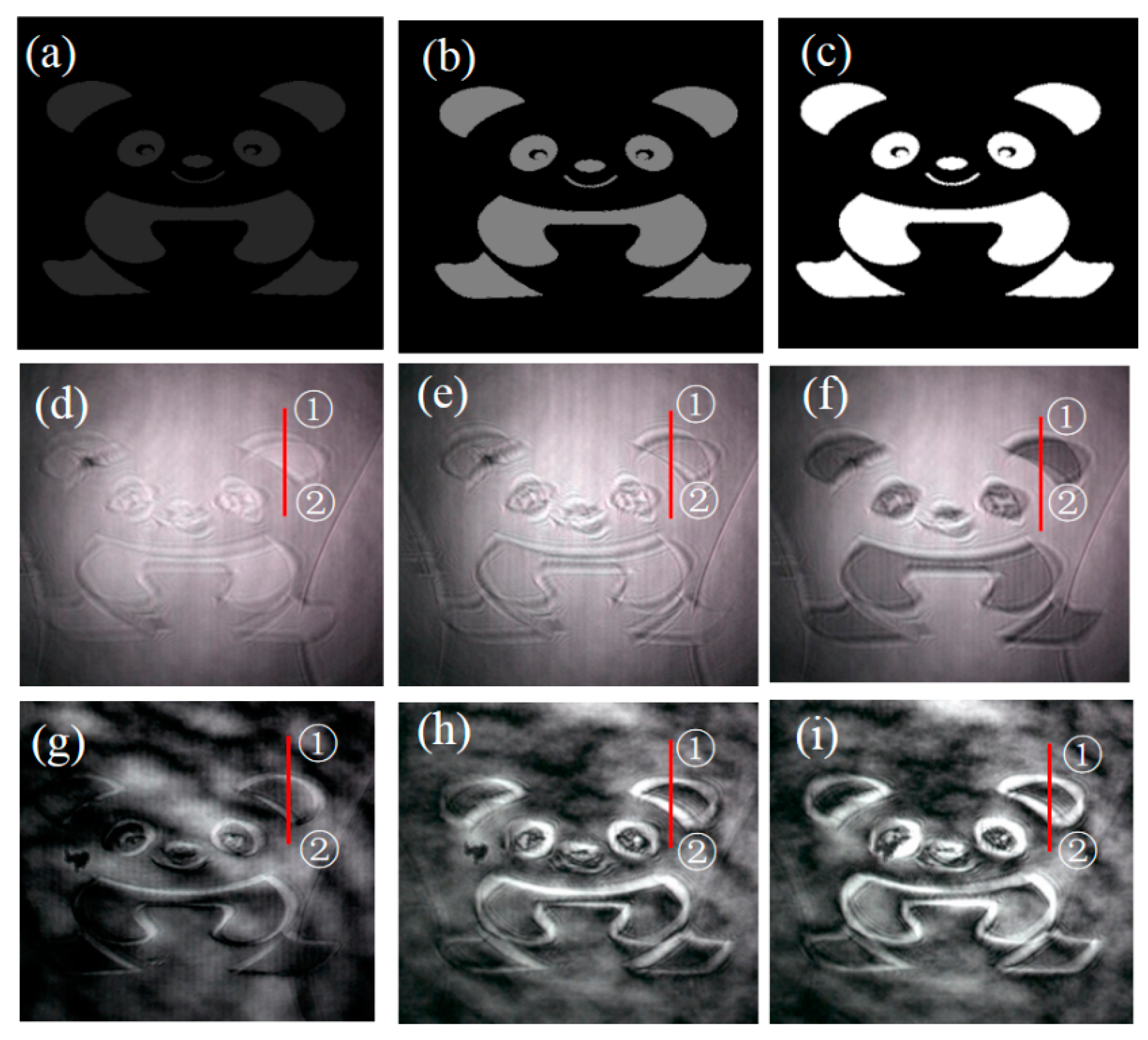
Figure 1. The two-step exposure process. (a) The first exposure step for homogeneous alignment. (b) The second exposure step using a graphical lithographic mask. (c) Configuration of FLC FG cell; the helical axis in the adjacent region is perpendicular to each other.
Photonics 11 00085 g001
Figure 2. Schematics of spiral phase contrast imaging system with switchable FLC FG. Illumination module I and Illumination module II are designed for transmittive and reflective objects, respectively.
Photonics 11 00085 g002
Figure 3. Microphotographs of proposed FLC FG under crossed polarizers. (a) −5 V driving voltage. (b) +5 V driving voltage. (c,d) are transmission pattern and diffraction pattern of FLC FG. (e) Configuration of FLC molecules under electric field in transmission mode and diffraction mode.
Photonics 11 00085 g003
Figure 4. Electro-optical response of the FLC FG. (a) The response waveform by applying a 10 V voltage. (b) The voltage-dependent switching time at 200 Hz.
Photonics 11 00085 g004
Figure 5. Experimental results of spiral phase contrast image. (a) Bright field image of an amplitude object of Illumination module I. (c) Bright field image of a pure phase object of Illumination module II. (b,d) are the edge-enhanced spiral phase filtered images.
Photonics 11 00085 g005
Figure 6. Comparison images of the fork grating’s slight shift: (ae) display the point spread function for no shift, left shift, right shift, up shift, and down shift, respectively; (fj) represent the edge-enhanced images for no shift, left shift, right shift, up shift, and down shift, respectively.
Photonics 11 00085 g006
Figure 7. Edge-enhancement experiment results of pure phase panda images with different phase steps. (ac) are the phase-type object of panda pattern with phase step of π/3, 2π/3, and π respectively. (df) are the bright field images of (ac). (gi) are the edge-enhanced images of (ac).
Photonics 11 00085 g007
Table 1. Edge contrast C of pure phase object with different phase steps.
Phase Stepπ/32π/3π
① in bright field image6.3%30.5%50.0%
② in bright field image16.7%18.4%37.9%
① in edge-enhanced image33.2%66.8%82.4%
② in edge-enhanced image32.8%87.1%94.5%
Disclaimer/Publisher’s Note: The statements, opinions and data contained in all publications are solely those of the individual author(s) and contributor(s) and not of MDPI and/or the editor(s). MDPI and/or the editor(s) disclaim responsibility for any injury to people or property resulting from any ideas, methods, instructions or products referred to in the content.

