Article

Lightning Location Method Using Orthogonal Coded Polarization Optical Time-Domain Reflectometer in Optical Fiber Transmission

1
China Southern Power Grid Company, Ltd., Guangzhou 510530, China
2
Wuhan National Laboratory for Optoelectronics, Huazhong University of Science and Technology, Wuhan 430074, China
*
Author to whom correspondence should be addressed.
Photonics 2024, 11(10), 925; https://doi.org/10.3390/photonics11100925
Submission received: 3 September 2024 / Revised: 20 September 2024 / Accepted: 27 September 2024 / Published: 30 September 2024
(This article belongs to the Section Optical Communication and Network)

Abstract

:
Lightning strike is one of the main factors affecting power transmission lines and may lead to broken strands and damage of transmission lines, resulting in abnormal power supply. To improve the accuracy of lightning location, this paper presents a polarization optical time-domain reflectometer (POTDR) lightning location method based on orthogonal coding technology. The lightning strike point can be located by detecting the state of polarization (SOP) mutation of Rayleigh backscattering in the POTDR system. The orthogonal coding technology is used to improve the distance and accuracy of POTDR lightning location. Through calculation and simulation analysis, the location accuracy is significantly improved at the same sensing distance compared with the ordinary POTDR lightning location method. The lightning strike location error can be limited to 200 m in 20 km sensing distance which meets the actual engineering needs. The results of this paper are important to improve the operation and maintenance efficiency of transmission lines and reduce maintenance costs in the power industry.

1. Introduction

Lightning strike is one of the main factors affecting power transmission lines, which and may lead to broken strands and damage of transmission lines, resulting in abnormal power supply. It is necessary to locate lightning strikes, and the accuracy of lightning location has attracted a lot of research interest. The existing lightning location technology can be divided into two categories: one is electrical lightning location based on electromagnetic field or voltage and current measurement; the other is optical lightning location technology based on an optical fiber composite overhead ground wire (OPGW).
In previous research, the electrical methods for lightning location have been widely applied. In the 1970s, a magnetic direction finder which utilizes the initial few microseconds of wide-band return stroke waveforms was developed to provide accurate directions to the channel bases of lightning discharges to ground. The results showed that the angular resolution of lightning storms at distances of 10 to 100 km is from 1° to 2° [1], which is one of the early studies on lightning location. In the 1990s, a lightning location system (LLS) was widely used worldwide, and a GPS-based three-dimensional lightning mapping system was established in America, which measures the arrival time of impulsive very-high-frequency (VHF) radiation at six or more stations and uses the arrival times to locate lightning strikes [2]. The research results indicate that the average lightning positioning error of the system within a range of 60 km is about 300 m, and the main drawback of this system is the need for wide area time synchronization and high operational and maintenance costs. In 2004, a novel technique based on wavelet multiresolution analysis (MRA) which realizes feature extraction of traveling wave signals for lightning location was presented [3]. The simulation results show that the location error at a distance of 100 km is about 1 km, while the mismeasurement rate is high due to multiple reflections of traveling waves at the fault point. In 2021, a Bayesian framework which utilizes the necessary prior probability and likelihood functions to describe the distribution of location errors was presented to quantify the lightning location errors of LLS [4]. Generally, due to the problems of signal distortion, difficult detection of traveling waves, and high maintenance cost [1,2,3,4], optical methods for lightning location have attracted increasing attention from researchers in recent years.
In the past twenty years, several optical lightning location technologies have been proposed to address the technical shortcomings of the electrical lightning location methods, e.g., the double-ended method based on SOP measurement [5], the single-ended approach [6], and the Brillouin optical time-domain reflectometer (BOTDR) method based on fiber distributed sensing [7].
The double-ended method is based on SOP measurement, which emits continuous light from both ends and utilizes the time difference of SOP fluctuation to achieve lightning location [5]. This method requires precise time synchronization between the two ends, which has high operating and maintenance costs. The single ended approach emits continuous optical signal from the transmitter and loops back at the end of the fiber link, achieving lightning location through the time difference between two SOP fluctuation detected at the single end [6]. The lightning simulation experiment result shows that the maximum location error is about 166 m at a distance of 50 km. However, this method has a measurement blind spot and the end loop requires a long delay fiber. The BOTDR based lightning location technology achieves lightning location with the Brillouin frequency shift effect of OPGW optical signals caused by temperature rise during lightning strikes [7]. Lightning simulation experiment results indicate that the location error within a 500 m fiber link is about 16 m. In 2022, the experimental result in [8] shows that the BFS has an instantaneous rise of at least 8 MHz when the quantity of electric discharging is 125 C. However, fluctuation of external temperature and stress can also have a significant impact on the Brillouin frequency shift effect of optical signals in OPGW, resulting in significant location error [9].
Compared with the above schemes, POTDR lightning location technology utilizes the Faraday effect caused by lightning where the SOP of the optical signal rapidly fluctuates to locate lightning strikes [10,11,12,13,14,15,16]. Its advantage lies in the fact that the transmitter and receiver are deployed on the same side, which achieves low operating costs and high spatial resolution and does not require precise synchronization timing. Therefore, POTDR technology is used to achieve high-precision and low-cost lightning location. However, there is a key issue with using POTDR for lightning location, which is the low accuracy of lightning location when the fiber link is long. The main reason for this problem is that the ordinary POTDR lightning location system (POTDR-LLS) cannot accurately locate lightning strikes that occur in areas where the detection light pulse has already passed, and it will be analyzed in detail in Section 2.2.
To address the low accuracy of POTDR lightning location in long sensing distances, we propose a POTDR lightning location method based on multi-pulse orthogonal coding technology. On one hand, utilizing multi-pulse orthogonal coding technology can improve the detection distance. On the other hand, it can reduce location errors in the POTDR lightning location system. Through calculation and simulation analysis, the lightning strike location error can be limited to 200 m in a 20 km sensing distance, which meets the actual engineering needs. Compared with the most widely used LLS based on electromagnetic field measurement, the orthogonal coded POTDR-LLS inherits the ordinary POTDR-LLS technical advantages and has higher accuracy in long sensing distances. The main novelty of the orthogonal coded POTDR-LLS is applying the orthogonal coding technique to allow multiple light pulses propagating in the measured optical fiber link, which will ensure that there are always light pulses that can accurately locate the lightning strike point.
This paper is structured as follows: Section 2 describes the proposed orthogonal coded POTDR-LLS; Section 3 reports the simulation results of the proposed orthogonal coded POTDR-LLS; lastly, Section 4 concludes the paper.

2. Theory and Analysis

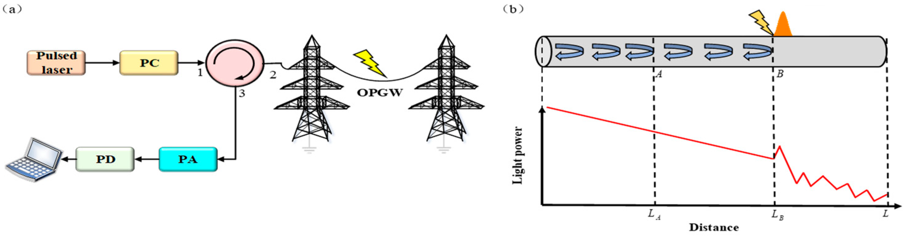
2.1. Principle of POTDR

The structure of the POTDR lightning location system is shown in Figure 1a. The pulsed laser launches light pulses which are polarized by the polarization controller (PC) and directed to the fiber link of the OPGW with the circulator. The SOP mutation of the Rayleigh backscattered light caused by a lightning strike is transferred into intensity variation by a polarization analyzer (PA). Using a photodetector (PD) and a computer, the intensity variation is captured for obtaining the lightning strike location.
The principle of POTDR lightning location scheme is shown in Figure 1b. When the lightning strikes occur along the OPGW, a spirally distributed current flows through the outside metal tube, forming a structure like an electrified solenoid which excites a magnetic field along the fiber. Then, the axial component of the magnetic field causes the Faraday rotation effect, resulting in an SOP mutation. The intensity of the received light decreases with the transmission distance due to the fiber attenuation and fluctuates due to the SOP mutation when there is a lightning strike.
The rotation angle of the optical vector is positively correlated with magnetic induction intensity and the length of the magnetic field generated by lightning strikes. The relationship is
θ = V B L 0
where θ is the rotation angle of the optical vector caused by lightning strikes, V is the Verdet constant, B is the magnetic induction intensity, L0 is the length of the magnetic field generated by lightning strikes. For standard single-mode fibers, the Verdet constant at the wavelength of 1550 nm is approximately 0.53 rad/(T·m) at room temperature.
When the Rayleigh backscattering light signal from the lightning strike point is received by the photodetector through the polarization analyzer, the photodetector directly detects the light power. According to the Malus law, the rotation of the SOP of the light signal caused by lightning strike is detected by the POTDR-LLS in the form of power mutation, which is given by
I = I 0 cos 2 ( θ )
where I0 is the optical power before the Rayleigh backscattering light passes through the polarization analyzer, I is the detected optical power of the photodetector, and θ is the rotation angle of SOP caused by lightning strikes. Based on the impact of lightning strikes on the SOP of optical signals and the Malus law, the POTDR-LLS detects the fluctuations in light power corresponding to each scattering point to find the power mutation point and achieve lightning location.
However, the POTDR-LLS is not always accurate. When a lightning strike occurs at point B while the light pulse has already passed through the lighting strike point, according to the principle of the POTDR-LLS, there will be lightning location errors. The specific process will be discussed in the next section. The location error is more likely to occur when the fiber link is long due to the randomness of the position and time of the lightning strikes. Generally, the ordinary POTDR lightning location method has larger lightning location errors when the fiber link is long, which will be analyzed in detail in Section 2.2.

2.2. Errors in POTDR Lightning Location

As mentioned above, since the POTDR emits optical signals from one end and then detects the reflected signals, the randomness of lightning strikes can lead to three different positional relationships of the lightning strike point and the light pulse during lightning location. Firstly, the light pulse arrives at the lightning strike point just after the lightning strike occurs; secondly, the light pulse has not yet arrived at the lightning strike point when the lightning strike occurs; thirdly, the light pulse has already passed through the lightning strike point when the lightning strike happens. When the light pulse arrives at the lightning strike point just after the lightning strike occurs or has not yet arrived at the lightning strike point, the system can accurately locate the lightning strike point, as shown in Figure 1. When lightning strike occurs at point B, and the light pulse reaches point A, as shown in Figure 2a, if the total sensing distance L matches
L c τ 2 n
where c is the speed of light in vacuum, τ is the lightning relaxation time, and n is the refractive index of the fiber core, then the distance from point A to point B is
Δ L = L B L A c τ n
which means when the light pulse reaches point B from point A, the magnetic field generated by the lightning strike does not disappear. At this time, the optical pulse can accurately locate the location of the lightning strike. The extreme case in Figure 2a is that the two points A and B coincide; that is, the light pulse just reaches the lightning strike point, as shown in Figure 1, in which the lightning strike point detected by the system also has no positioning error.
There is a serious error when the light pulse has passed the lightning strike point when a lightning strike happens, as shown in Figure 2b.
If the total sensing distance L matches
L > c τ 2 n
then the lightning location error can be given by Δ L = ( L B L A ) / 2 . If the detection light pulse is transmitted at time 0, the optical signal received at time t at the receiving end is Rayleigh backscattering light from the point whose distance to the receiving end is v t / 2 . When the detection pulse reaches point B, if the lightning strike occurs at point A, according to the POTDR positioning principle, the detected lightning location point is the midpoint C of point A and B. If the system requires the lightning location error to be 0, and the total sensing distance meets Equation (3), when the next light pulse emitted at an interval of one period T = 2 n L / c reaches point A, the lightning strike has ended.
According to previous research on the SOP of Rayleigh backscattering light [17], the degree of polarization of Rayleigh backscattering light is one-third, which means only one-third of the light is polarized. Therefore, the polarized light intensity received by the POTDR-LLS is very weak, resulting in the lightning location method which is based on the POTDR detecting SOP mutations only being able detect very short distances. Correspondingly, within a long distance, according to Figure 2b, the received light cannot be used to accurately locate lightning strikes. Therefore, it is necessary to find a new method that can increase the total sensing distance of the POTDR-LSS and ensure accurate lightning location when the fiber link is long.

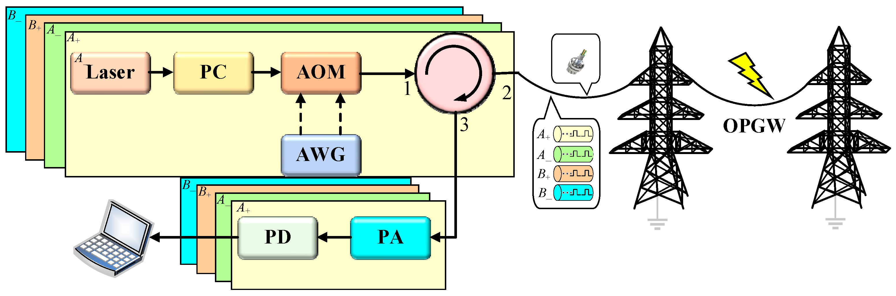
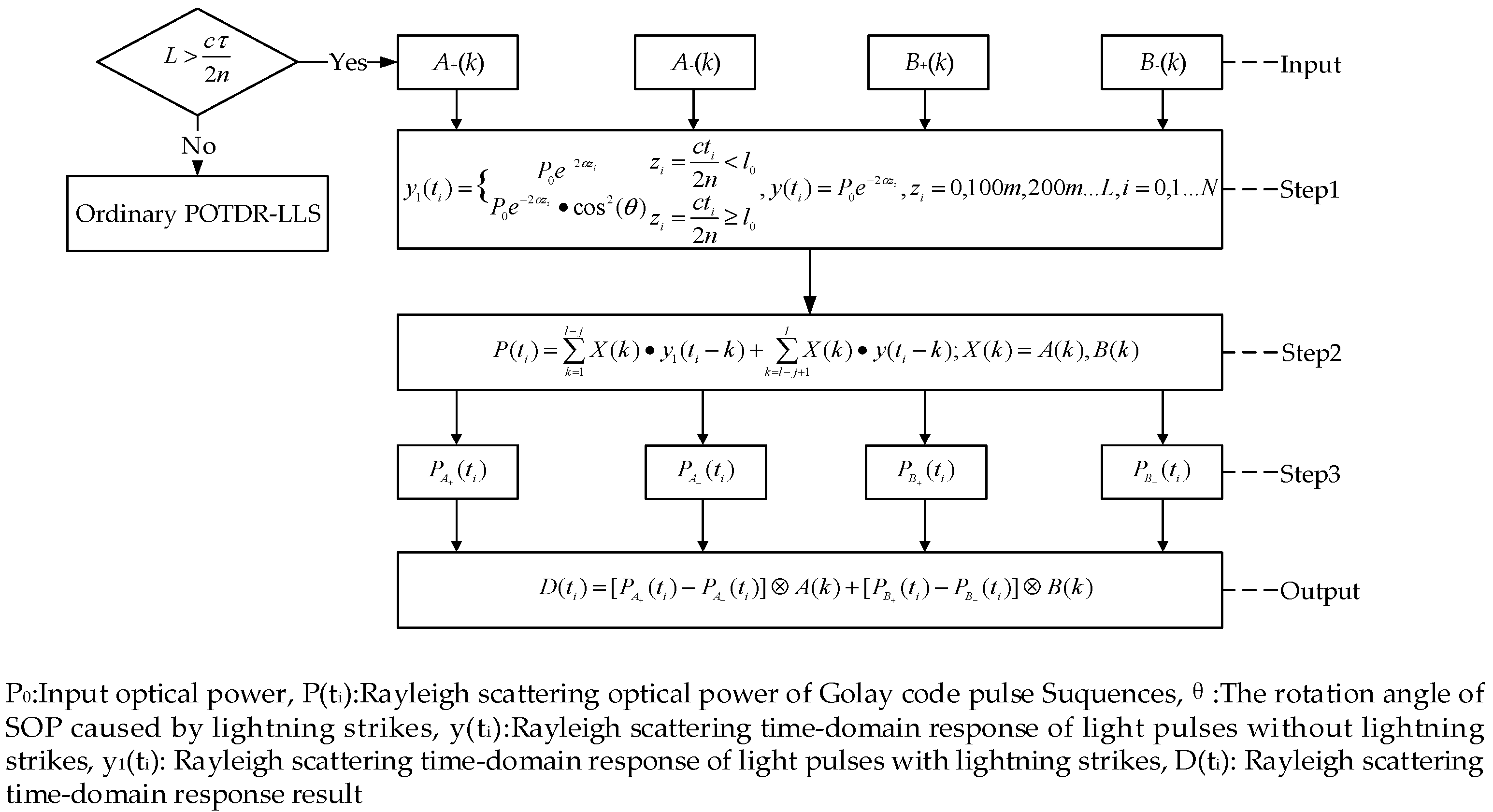
2.3. The Principle of Orthogonal Coded POTDR for Lightning Location

In order to solve the above technical problems of the ordinary POTDR-LLS, we propose the orthogonal coded POTDR-LSS, as shown in Figure 3. By transmitting multiple pulses instead of a single pulse into the optical fiber, it is ensured that there are always several pulses that have not reached the lightning strike point. These pulses are decoded at the receiving end and can accurately locate the lightning strike point. As shown in Figure 3, the continuous optical signal emitted by the laser is polarized by the PC and modulated into a sequence by an acousto-optic modulator (AOM) controlled by an arbitrary waveform generator (AWG). And the signal is then transmitted into the OPGW line through a circulator. The information at different points of the optical fiber is loaded onto the RBS through SOP and received by the PD. The computer converts it into a POTDR curve containing information of the lightning strike point. Taking Golay code as an example, in order to reduce the lightning location errors, the four subsequences of Golay code A+, A and B+, B are emitted to four different fibers of the OPGW simultaneously by four sets of transceivers as, shown in Figure 3.
When orthogonal coding technology is adopted, the Rayleigh backscattering time-domain response of a single light pulse is recovered by decoding at the receiving end, which contains the accurate information of the SOP mutation point generated by multiple light pulses that have not passed through the lightning strike point at the time of the lightning strike, so it can reduce the positioning error caused by the first light pulse passing through the lightning strike point at the time of the lightning strike compared with the ordinary POTDR-LSS. Meanwhile, the system emits multiple detection light pulses rather than a single light pulse in a short time, which can improve the intensity of the optical signal containing SOP mutation information in Rayleigh backscattering light and solve the problem of the low degree of polarization of Rayleigh backscattering light.
Take Golay code as an example, which is composed of two sequences A and B [18]. The sequence A and B are composed of four sub columns A+, A and B+, B. The expression of each subsequence is given by
A + ( k ) = ( 1 + A ( k ) ) / 2 A ( k ) = ( 1 A ( k ) ) / 2 B + ( k ) = ( 1 + B ( k ) ) / 2 B ( k ) = ( 1 B ( k ) ) / 2
Let the time-domain Rayleigh backscattering response function of a single light pulse be y(t). In the coded POTDR lightning location system, the four subsequences of Golay code A+, A and B+, B are emitted to different fiber cores of the OPGW simultaneously by four sets of transceivers as shown in Figure 3. The final POTDR measurement result without the lightning strike is
C ( t ) = [ A + ( k ) y ( t ) A ( k ) y ( t ) ] A ( k ) + [ B + ( k ) y ( t ) B ( k ) y ( t ) ] B ( k ) = 2 l δ ( k ) y ( t )
where l is the length of the Golay-coded sequence, * is the convolution operator, ⊗ is the autocorrelation operator. The final POTDR measurement result without the lightning strike is 2l times the Rayleigh backscattering time-domain response of a single light pulse.
Simplex code is a unipolar matrix constructed from a Hadamard matrix. The Hadamard matrix is constructed by
H 1 = [ 1 ]
H 2 n = H n H n H n H n
When n is 4 or a multiple of 4, remove the first row and the first column of the Hadamard matrix and perform the formula as follows on the remaining matrix elements to obtain an S-matrix of order n − 1:
a = 1 a 2
where a′ is the element of the S matrix and a is the element of the Hadamard matrix. From Equation (10), it is shown that “1” of the original Hadamard matrix becomes “0” and “−1” becomes “1” in the S matrix [19,20,21,22,23]. Since the simplex code is unipolar, there is no need to convert the bipolar code to the unipolar code when it is used to encode the light pulses of the POTDR-LLS, and the decoding process does not need to carry out autocorrelation operations. It only needs to multiply the Rayleigh backscattering time-domain response matrix of the optical fiber and the inverse matrix of the S matrix to restore the Rayleigh backscattering time-domain response of the light pulse, which is suitable for the orthogonal coded POTDR-LSS. The orthogonal coding technique is mainly used in the OTDR system to increase the total optical energy injected into the fiber to improve the signal-to-noise ratio (SNR) of the received Rayleigh scattering light, and after demodulation through specific signal processing methods, the spatial resolution can be maintained unchanged [24,25]. In practical use, the pulse sequence synchronizing can be achieved by applying a synchronous control circuit at the transmitting end, which is more cost effective than wide area precise time synchronization. At the receiving end, the decoding operation is processed offline; only the emission of each pulse sequence and the reception of Rayleigh scattered light signals require the use of a data acquisition card for synchronization.
When the total sensing distance meets Equation (3), the light pulse cannot accurately locate the lightning event in the optical fiber area it has passed after the light pulse of the ordinary POTDR-LLS is transmitted, while during the transmission of the light pulse sequences, the coded POTDR-LLS can ensure the accurate location of lightning strikes in the optical fiber area covered by the light pulse sequences. Compared with the ordinary POTDR-LLS, the length of the fiber link where the coded POTDR-LLS can accurately locate lightning strikes has increased by ΔL′, that is:
Δ L = c Δ t n × ( l e n g t h 1 )
where c is the speed of light in vacuum, n is the refractive index of the fiber, Δt is the transmission interval of adjacent light pulses, and length is the encoding length. In general, the orthogonal coded POTDR lightning location method can improve the positioning accuracy and increase the sensing distance of POTDR-LLS.

3. Simulation Results and Discussion

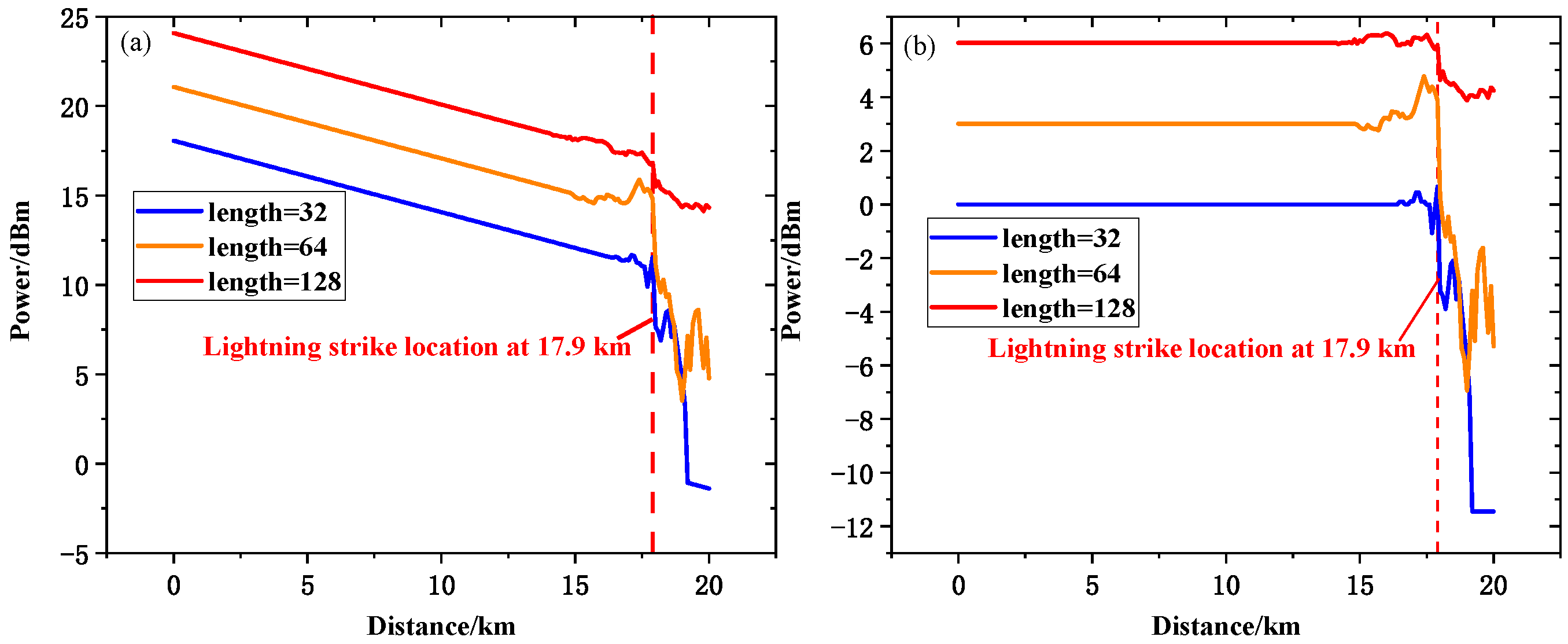
3.1. Simulation of POTDR Lightning Location System Based on Golay Code

We build the simulation platform according to the system in Figure 3, and the simulation algorithm of orthogonal coded POTDR-LLS is shown in Figure 4. We use Matlab to set up the simulation system; the simulation algorithm is mainly based on modeling of Fiber Rayleigh Scattering Channel and autocorrelation decoding process [26]. As shown in Figure 4, if the total sensing distance L matches Equation (5), taking Golay-coded POTDR-LLS as an example, the Rayleigh scattering time-domain response power results P(ti) of four subsequences are calculated independently. Firstly, the Rayleigh scattering time-domain response of light pulses is divided into two kinds, in which the modeling of Fiber Rayleigh Scattering Channel is used to calculate the power of Rayleigh scattered light at the corresponding point by taking points at a certain distance in the optical fiber to form a POTDR curve. The next step is adding up the Rayleigh scattering time-domain response results of the light pulses according to subsequences they belong to obtain the detected results of the four subsequences. Finally, the four Rayleigh scattering time-domain response results are decoded with autocorrelation decoding process to get the final Rayleigh scattering time-domain response result D(ti).
In our previous research, the SOP of the actual OPGW was monitored for three months in lightning-prone areas and the maximum detected SOP rotation speed was up to 43 Mrad/s [27], which is much larger than SOP rotation caused by other environmental factors such as external temperature variations or mechanical stress on the fiber. Thus, the sensitivity of the orthogonal coded POTDR-LLS to other environmental factors is not taken into consideration in our simulation. The key parameters are shown in Table 1.
In the simulation of the Golay-coded POTDR lightning location system, four light pulse sequences are transmitted into the OPGW simultaneously, as shown in Figure 3. Supposing the lightning relaxation time is 40 μs, the rotation of the state of polarization (RSOP) caused by the lightning is 5.1 Mrad/s [28], and the transmission interval between adjacent pulses of the light pulse sequences is 1 μs, then the rotation angle difference of the SOP caused by the lightning strike between the two adjacent optical pulses is 5.1 rad. We use the Malus law to reflect the SOP mutation of optical signal caused by lightning strike. The Golay-coded sequences with different lengths of 32/64/128 are used to observe the impact of different coding lengths on lightning location accuracy.
In the simulation, the actual lightning strike point is set at 18.1 km. In order to set a clear criterion for lightning location, the four-point event loss is used to judge the detected lightning strike point, which subtracts the average optical power within 100 m before and after a certain point on the POTDR curve. If the difference is greater than 3 dB, it is determined that the SOP at that point has undergone a mutation due to lightning strikes. As shown in Figure 5a, there is a steep power drop larger than 3 dB at 17.9 km on the POTDR curve. The power mutation is clearer in differential results, as shown in Figure 5b. Therefore, the positioning error is within 200 m. Generally, the transmission lines in the power system are grounded tower by tower, so lightning strikes only affect the OPGW between the two adjacent towers and have no impact on the other parts of the OPGW. The distance between adjacent towers is generally about 300 m, so the location accuracy can meet the actual needs of lightning location in power systems. The different pulses in the same Golay-coded light pulse sequence suffer from different transmission processes, some of which are affected by the lightning strike, while others are not, as the relaxation time of lightning strikes is short. So, the Rayleigh backscattering time-domain response function of lightning strikes to the light pulse is different. Let the sequence length be l; only the last j pulses have not passed through the lightning strike point at the time of lightning strike, while the first lj pulses have passed. The Rayleigh backscattering time-domain response function of the last l optical pulse is y(t), and the Rayleigh scattering time-domain response function of the first lj optical pulse is y1(t); then, the POTDR detection result at the time of lightning strike is:
D ( t ) = k = 1 l j A + ( k ) A ( k ) y 1 ( t ) + k = l j + 1 l A + ( k ) A ( k ) y ( t ) A ( k ) + k = 1 l j B + ( k ) B ( k ) y 1 ( t ) + k = l j + 1 l B + ( k ) B ( k ) y ( t ) B ( k )
The lightning location error and the disturbance before the power mutation point are caused by the crosstalk with side lobe of the self-correlation decoding operation not being 0, which is owing to the difference between y(t) and y1(t) in the above formula. Other potential sources of error mainly include electrical signal noise caused by impedance mismatch in the conversion circuit of the photodetector and the limitation of the line width and power stability of the light source. The first type of error source can be reduced by using moving average or the Savitzky–Golay (SG) filtering algorithm [29]. The second kind of error source is decreased by choosing a light source with line width closer to 0.2 nm and peak-to-peak power stability less than 8% [30]. If multiple lightning strikes occur in the fiber link within one detection cycle, the multiple lightning strike location can be realized by reducing the length of the pulse sequence to emit multicycle light pulse sequence into the fiber link and converting the time domain response results of the POTDR to frequency domain by fast Fourier transform (FFT) [30]. The multiple lightning strike points can be detected by finding power mutation points in the frequency domain.
According to Equation (12) and Figure 5, it is apparent that the length of the fiber link where the system can accurately locate lightning strikes increases with the increase in the coding length, but the steep power drop caused by lightning strike will decrease, which will affect the determination of lightning location points. Therefore, the selection of Golay-coded POTDR-LLS should comprehensively consider the determination of lightning location points and the length of the fiber link where the lightning strikes are accurately located.

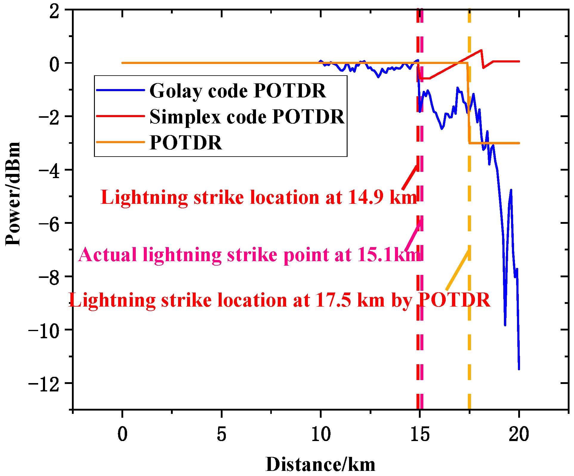
3.2. Comparison of Location Accuracy of Different POTDR Lightning Location Schemes

In order to study the influence of different code types on the positioning accuracy of orthogonal coded POTDR-LLS, we carried out the simulation of POTDR-LSS based on simplex code and compared the positioning accuracy of orthogonal coded POTDR-LLS with that of ordinary POTDR-LLS. In the simulation of the Simplex-coded POTDR-LLS, we suppose that multiple light pulse sequences of the S matrix are emitted and transmitted in different fibers of the OPGW at the same time, and the influence of lightning strikes on the SOP of the optical signal is expressed as RSOP. The coding length of the Simplex code is 127, and the number of pulse sequences emitted at the same time is four or eight groups. In the simulation, the actual lightning strike point is set at 18.1 km. Figure 6 shows that the light power drops sharply at 17.9 km on the POTDR curve, and the positioning error is within 200 m. With the increase in the number of light pulse sequences emitted at the same time, the steep power drop effect caused by lightning strike is more obvious, which makes it easier to identify the lightning strike point, while the practical feasibility of Simplex-coded POTDR will decline due to the limitation of the transceivers.
In order to compare the general performance of different POTDR-LLSs, the actual lightning strike point is set at 15.1 km, the coding length of Golay-coded POTDR-LSS is 128, the coding length of Simplex-coded POTDR-LSS is 127 with 32 groups of light pulse sequences transmitted at the same time, and the ordinary POTDR-LLS is simulated when the first light pulse has passed through the lightning strike point and reached 20 km at the time of lightning strike. The results are shown in Figure 7.
As shown in Figure 7, the ordinary POTDR-LSS error is 2.5 km, which is much larger than the positioning error of the orthogonal coded POTDR-LLS. In the two orthogonal coded POTDR lightning location schemes, the power mutation degree of the Simplex-coded POTDR lightning location scheme with 32 groups of light pulse sequences simultaneously transmitted is still far less than that of the Golay-coded POTDR lightning location scheme in the differential diagram. The number of light pulse groups simultaneously transmitted by the Golay-coded POTDR-LLS is significantly less than that of the Simplex-coded POTDR-LLS when the positioning error is within 200 m. However, the Golay-coded POTDR-LLS requires autocorrelation operation for decoding, so there will be a power fluctuation for a certain distance before the detected lightning strike point, which may affect the determination of lightning location points in actual situation. The Simplex-coded POTDR-LLS has no power fluctuation before the detected lightning strike point because the decoding process does not require autocorrelation operation, which is more convenient for determining the lightning strike point.
As shown in Figure 7, the ordinary POTDR-LSS error is 2.5 km, which is much larger than the positioning error of the orthogonal coded POTDR-LLS. In the two orthogonal coded POTDR lightning location schemes, the power mutation degree of the Simplex-coded POTDR lightning location scheme with 32 groups of light pulse sequences simultaneously transmitted is still far less than that of the Golay-coded POTDR lightning location scheme in the differential diagram. The number of light pulse groups simultaneously transmitted by the Golay-coded POTDR-LLS is significantly less than that of the Simplex-coded POTDR-LLS when the positioning error is within 200 m. However, the Golay-coded POTDR-LLS requires autocorrelation operation for decoding, so there will be a power fluctuation for a certain distance before the detected lightning strike point, which may affect the determination of lightning location points in actual situation. The Simplex-coded POTDR-LLS has no power fluctuation before the detected lightning strike point because the decoding process does not require autocorrelation operation, which is more convenient for determining the lightning strike point. In practical use, compared with Golay code, Simplex code needs to emit more light pulse sequences to locate lightning strikes, and the length of the pulse sequence increases with the increase in the number of pulse sequences, which means Simplex code POTDR-LLS requires more transceivers and longer detection cycle leading to decrease in lightning location efficiency. The number of light pulse sequences of Golay code is fixed, but the positioning accuracy with the same pulse sequence length is lower compared with Simplex code. Thus, if the lightning location efficiency is the main requirement of the POTDR-LLS system, the priority should be given to using Golay code. If location accuracy is the main performance indicator, then it is better to choose Simplex code.
To further illustrate the potential application value of the orthogonal coded POTDR-LLS described in this article, a comparison table summarizing key parameters of various existing lightning location technologies is listed in Table 2.
As shown in Table 2, it is apparent that the orthogonal coded POTDR-LLS has a relatively lower location accuracy in an appropriate sensing distance for engineering application, and its mismeasurement rate and maintenance cost are both low, which outperform other existing lightning location technologies.
In general, the orthogonal coded POTDR-LLS can significantly improve the lightning location accuracy compared with the ordinary POTDR-LLS. In the two orthogonal coded POTDR lightning location schemes, the Golay-coded POTDR lightning location scheme needs fewer light pulse groups to be transmitted at the same time, whose practical feasibility is higher. The power fluctuation in the measurement results of the Simplex-coded POTDR lightning location scheme is smaller, which is more convenient for determining the lightning strike point.

4. Conclusions

In this paper, a POTDR lightning location method based on orthogonal coding technology is proposed. The orthogonal coding technology is used to improve the positioning accuracy of the long-distance POTDR lightning location system. Compared with the ordinary POTDR lightning location method, the positioning accuracy is significantly improved under the same sensing distance. When the total sensing distance is 20 km, the location error of the two orthogonal coded POTDR lightning location schemes is less than 200 m, which meets the actual engineering needs. We also compare the performance of different code types and code lengths of a coded POTDR lightning location scheme.

Author Contributions

Conceptualization, W.L. (Weihua Lian), X.S. and W.L. (Wei Li); methodology, W.L. (Weihua Lian), X.S., B.W. and W.L. (Wei Li); software, W.L. (Weihua Lian), X.S. and X.F.; validation, W.L. (Weihua Lian), X.S., B.W., X.F. and W.L. (Wei Li); formal analysis, W.L. (Weihua Lian), X.S., H.Z., D.W. and K.H.; investigation, W.L. (Weihua Lian), X.S., B.W., X.F., H.Z., D.W. and G.W.; resources, W.L. (Weihua Lian), X.S., B.W., X.F., H.Z., D.W. and W.L. (Wei Li); data curation, W.L. (Weihua Lian), X.S., G.W., L.L., Y.C. and K.H.; writing—original draft preparation, W.L. (Weihua Lian), X.S., G.W., L.L., Y.C. and K.H.; writing—review and editing, W.L. (Weihua Lian), X.S., B.W., X.F., H.Z., D.W. and W.L. (Wei Li); visualization, W.L. (Weihua Lian), X.S. and W.L. (Wei Li); supervision, W.L. (Weihua Lian), X.S. and W.L. (Wei Li); project administration, W.L. (Weihua Lian), X.S. and W.L. (Wei Li); funding acquisition, W.L. (Weihua Lian) and W.L. (Wei Li). All authors have read and agreed to the published version of the manuscript.

Funding

This research was funded by the China Southern Power Grid.

Institutional Review Board Statement

Not applicable.

Informed Consent Statement

Not applicable.

Data Availability Statement

The data presented in this study are available on request from the corresponding author due to the sensitive nature of the data and legal restrictions preventing public disclosure.

Acknowledgments

The authors would like to thank the China Southern Power Grid and Wuhan National Laboratory for Optoelectronics for the support.

Conflicts of Interest

The authors declare no competing interests. The authors Weihua Lian, Bin Wu, Xiaofang Feng, Hanqi Zhao, Desong Wang, Guilong Wu, Lin Liu, and Yitong Chen were employed by the company China Southern Power Grid Company, Ltd. There is no conflict of interest between any of the authors and the company China Southern Power Grid Company, Ltd.

References

  1. Krider, E.; Noggle, R.; Gated, M.A.U.A. Wideband Magnetic Direction Finder for Lightning Return Strokes. J. Appl. Meteorol. Clim. 1976, 15, 301–306. [Google Scholar] [CrossRef]
  2. Rison, W.; Thomas, R.; Krehbiel, P.; Hamlin, T.; Harlin, J. A GPS-based three-dimensional lightning mapping system: Initial observations in central New Mexico. Geophys. Res. Lett. 1999, 26, 3573–3576. [Google Scholar] [CrossRef]
  3. Chanda, D.; Kishore, N.K.; Sinha, A.K. A wavelet multiresolution-based analysis for location of the point of strike of a lightning overvoltage on a transmission line. Power Deliv. IEEE Trans. Power Deliv. 2004, 19, 1727–1733. [Google Scholar] [CrossRef]
  4. Hunt, G. Lightning Location System Detections as Evidence: A Unique Bayesian Framework. IEEE Trans. Geosci. Remote Sens. 2021, 59, 1848–1858. [Google Scholar] [CrossRef]
  5. Qin, Z.; Cheng, Z.; Zhang, Z.; Zhu, J.; Li, F. New method for lightning location using optical ground wire. Chin. Opt. Lett. 2006, 4, 712–714. [Google Scholar]
  6. Deng, H.; Zhang, R.; Chen, J.; Zhang, H.; Guo, L. Research on Principles and Methods of Lightning Strike Location Based on OPGW Light Polarization State. Insul. Surge Arresters 2018, 2018, 148–153. [Google Scholar]
  7. Lu, L.; Liang, Y.; Li, B.; Guo, J.; Zhao, H.; Zhang, X. Location of lightning stroke on OPGW by use of distributed optical fiber sensor. In Proceedings of the 2014 International Symposium on Optoelectronic Technology and Application, Beijing, China, 13–15 May 2014; p. 92972I-92972I-6. [Google Scholar]
  8. Ji, Y.; Shao, J.; Li, S.; Zhou, Q. Study on Distributed OPGW Lightning Strike Location Monitoring System Based on BOTDR. In Proceedings of the 2022 Asia Communications and Photonics Conference (ACP), Shenzhen, China, 5–8 November 2022; pp. 1978–1980. [Google Scholar]
  9. Lu, L.; Liang, Y.; Li, B.; Guo, J.; Zhao, H.; Zhang, X. Experimental study on location of lightning stroke on OPGW by means of a distributed optical fiber temperature sensor. Opt. Laser Technol. 2015, 65, 79–82. [Google Scholar] [CrossRef]
  10. Kim, B.; Park, D.; Choi, S. Use of polarization-optical time domain reflectometry for observation of the Faraday effect in single-mode fibers. IEEE J. Quantum Electron. 1982, 18, 455–456. [Google Scholar]
  11. Rogers, A.J. Polarization-optical time domain reflectometry: A technique for the measurement of field distributions. Appl. Opt. 1981, 20, 1060–1074. [Google Scholar] [CrossRef]
  12. Ellison, J.G.; Siddiqui, A.S. A fully polarimetric optical time-domain reflectometer. IEEE Photon. Technol. Lett. 1998, 10, 246–248. [Google Scholar] [CrossRef]
  13. Wulipart, M.; Megret, P.; Blondel, M.; Rogers, A.J.; Defosse, Y. Measurement of the spatial distribution of birefringence in optical fibers. IEEE Photon. Technol.Lett. 2001, 13, 836–838. [Google Scholar] [CrossRef]
  14. Huang, Z.; Yuan, Y. POTDR based Power Communication Optical Cable Anti External Force Damage Monitoring System. J. Phys. Conf. Ser. 2021, 2005, 012219. [Google Scholar] [CrossRef]
  15. Charlton, D.; Clarke, S.; Doucet, D.; O’Sullivan, M.; Peterson, D.; Qilson, D.; Wellbrock, G.; Belanger, M. Field measurements of SOP transients in OPGW, with time and location correlation to lightning strikes. Opt. Express 2017, 25, 9689–9696. [Google Scholar] [CrossRef]
  16. Wang, X.; Hu, J.; Wang, F.; Yong, Y.; Zhang, Y.; Xue, M.; Zhang, X.; Pan, S. Multi-vibration detection by probe pulses with ergodic SOPs in a POTDR system. Opt. Express 2018, 26, 28349–28362. [Google Scholar] [CrossRef]
  17. van Deventer, M.O. Fundamentals of Bidirectional Transmission over a Single Optical Fiber. Ph.D. Thesis, Technische Universiteit Eindhoven, Eindhoven, The Netherlands, 1994. [Google Scholar]
  18. Nazarathy, M.; Newton, S.A.; Giffard, R.P.; Moberly, D.S.; Sischka, F.; Trutna, W.R.; Foster, S. Real-Time Long Range Complementary Correlation Optical Time Domain Reflectometer. J. Light. Technol. 1989, 7, 24–38. [Google Scholar] [CrossRef]
  19. Duckey, L.; Hosung, Y.; Kim, N.Y.; Lee, H.; Park, N. Analysis and Experimental Demonstration of Simplex Coding Technique for SNR Enhancement of OTDR. In Proceedings of the Lightwave Technologies in Instrumentation and Measurement Conference, Palisades, NY, USA, 19–20 October 2004; pp. 118–122. [Google Scholar]
  20. Park, J.; Bolognini, G.; Lee, D.; Kim, P.; Cho, P.; Pasquale, F.; Park, N. Raman-Based Distributed Temperature Sensor with Simplex Coding and Link Optimization. IEEE Photonic Technol. Lett. 2006, 17, 1879–1881. [Google Scholar] [CrossRef]
  21. Bolognini, G.; Park, J.; Kim, P.; Lee, D.; Pasquale, F.; Park, N. Performance enhancement of Raman-based distributed temperature sensors using Simplex codes. In Proceedings of the Optical Fiber Communication Conference (Optica Publishing Group, 2006), Anaheim, CA, USA, 5–10 March 2006. paper OTuL1. [Google Scholar]
  22. Bolognini, G.; Park, J.; Chiuchiarelli, A.; Park, N.; Di Pasquale, F. Improved Performance in Raman-Based Distributed Temperature Sensing with Coded OTDR and Discrete Raman Amplification. In Proceedings of the Optical Fiber Sensors. (Optica Publishing Group, 2006), Cancun, Mexico, 23–27 October 2006. paper ThE45. [Google Scholar]
  23. Soto, M.A.; Sahu, P.K.; Bolognini, G.; Di Pasquale, F. Brillouin-Based Distributed Temperature Sensor Employing Pulse Coding. IEEE Sens. J. 2008, 8, 225–226. [Google Scholar] [CrossRef]
  24. Muhammad, S.; Mehmood, H.; Naseem, A.; Abbas, A. Hybrid coding technique for pulse detection in an optical time domain reflectometer. Radio Eng. 2012, 21, 624–663. [Google Scholar]
  25. Sagues, M.; Piñeiro, E.; Cerri, E.; Minardo, A.; Eyal, A.; Loayssa, A. Two-wavelength phase-sensitive OTDR sensor using perfect periodic correlation codes for measurement range enhancement, noise reduction and fading compensation. Opt. Express 2021, 29, 6021–6035. [Google Scholar] [CrossRef]
  26. Liao, R.; Tang, M.; Zhao, C.; Wu, H.; Fu, S.; Liu, D.; Shum, P.P. Harnessing oversampling in correlation-coded OTDR. Opt. Express 2019, 27, 1693–1705. [Google Scholar] [CrossRef] [PubMed]
  27. Tong, F.; Hu, K.; Li, W.; Yu, S.; Lian, W.; Zhao, H.; Wu, B.; Hong, D.; Luo, M.; Hu, Q.; et al. Measurement of optical signal state of polarization in OPGW under lightning strike condition. In Proceedings of the 2024 Optical Fiber Communications Conference and Exhibition (OFC), San Diego, CA, USA, 24–28 March 2024; pp. 1–3. [Google Scholar]
  28. Zhao, W.; Zhao, J.; Zhang, H.; Gao, J.; Zhang, X. Channel modeling and compensation of ultra-fast spike-shaped RSOP caused by lightning. In Proceedings of the 2021 Asia Communications and Photonics Conference, Shanghai, China, 24–27 October 2021; pp. 1–3. [Google Scholar]
  29. John, A.; Sadasivan, J.; Seelamantula, C.S. Adaptive Savitzky-Golay Filtering in Non-Gaussian Noise. IEEE Trans. Signal Process. 2021, 69, 5021–5036. [Google Scholar] [CrossRef]
  30. Zhang, Z.; Bao, X. Distributed optical fiber vibration sensor based on spectrum analysis of Polarization-OTDR system. Opt. Express 2008, 16, 10240–10247. [Google Scholar] [CrossRef] [PubMed]
Figure 1. (a) Structure diagram of POTDR lightning location system; PC: polarization controller, PA: polarization analyzer. (b) Schematic diagram of POTDR lightning location system.
Photonics 11 00925 g001
Figure 2. (a) Schematic diagram of light pulse not passing through lightning strike point at the time of the lightning strike. (b) Schematic diagram of light pulse has passed through lightning strike point at the time of the lightning strike.
Photonics 11 00925 g002
Figure 3. Structure diagram of POTDR lightning location system based on orthogonal coding technology. PC: polarization controller, AWG: arbitrary waveform generator, AOM: acousto-optic modulator, PA: polarization analyzer.
Photonics 11 00925 g003
Figure 4. Simulation algorithm of orthogonal coded POTDR-LLS.
Photonics 11 00925 g004
Figure 5. (a) Golay-coded POTDR lightning location curves with different coding lengths. (b) Differential curves of Golay-coded POTDR lightning location system with different coding lengths.
Photonics 11 00925 g005
Figure 6. (a) Differential results of the lightning location scheme of the Simplex-coded POTDR with four row vectors transmitted simultaneously. (b) Differential results of lightning location scheme based on Simplex-coded POTDR with eight row vectors transmitted simultaneously.
Photonics 11 00925 g006
Figure 7. Comparison of positioning accuracy of different POTDR lightning location schemes.
Photonics 11 00925 g007
Table 1. Simulation parameters.
SymbolMeaningValue
L Optical fiber length20 km
L f Dynamic range40 km
T p Light pulse width10 μs
v Speed of light in optical fiber2 × 108 m/s
λ Optical signal wavelength1550 nm
l e n g t h G Golay code length32/64/128
l e n g t h S Simplex code length127
α Fiber loss0.2 dB/km
K Rayleigh Backscattering coefficient10−7
V rotation of the SOP5.1 Mrad/s
τ Lightning relaxation time40 μs
Δ τ Adjacent codes transmission time interval1 μs
l 0Lightning location18.1 km
Aracquisition rate2 Mhz
Wlaser linewidth0.2 nm
Wddetector bandwidth20 Mhz
Table 2. The key parameters of existing lightning location technologies.
TechnologyDistanceLocation ErrorMismeasurement RateMaintenance Cost
Orthogonal coded POTDR-LLS20 km *200 mlowlow
GPS-based three-dimensional lightning mapping system [2]60 km *300 mhighhigh
Feature extraction of traveling wave signals based on MRA [3]100 km *1000 mmediummedium
The single ended approach [6]50 km *166 mlowhigh
BOTDR-LLS [7]0.5 km *16 mhighlow
* All of the parameters in the table can be found in the introduction of this article.
Disclaimer/Publisher’s Note: The statements, opinions and data contained in all publications are solely those of the individual author(s) and contributor(s) and not of MDPI and/or the editor(s). MDPI and/or the editor(s) disclaim responsibility for any injury to people or property resulting from any ideas, methods, instructions or products referred to in the content.

