Article

Wavelength-Switchable 2 μm Single-Longitudinal-Mode Thulium-Doped Fiber Laser Based on Dual-Active Cavity and DLTCTR

1
School of Electronic and Information Engineering, Beijing Jiaotong University, Beijing 100044, China
2
School of Mechanical and Electrical Engineering, Xingtai University, Xingtai 054001, China
3
CRRC Technology Innovation (Beijing) Co., Ltd., Haidian District, Beijing 100083, China
4
Zhengzhou Key Laboratory of Low-Dimensional Quantum Materials and Devices, and College of Physics and Optoelectronic Engineering, Zhongyuan University of Technology, Zhengzhou 450007, China
*
Authors to whom correspondence should be addressed.
These authors contributed equally to this work.
Photonics 2024, 11(11), 1031; https://doi.org/10.3390/photonics11111031
Submission received: 9 October 2024 / Revised: 29 October 2024 / Accepted: 30 October 2024 / Published: 1 November 2024
(This article belongs to the Special Issue Single Frequency Fiber Lasers and Their Applications)

Abstract

:
A thulium-doped fiber laser (TDFL) with a dual-active cavity and a directly linked three-coupler triple-ring filter is designed and demonstrated. Its operational principle is analyzed, and a corresponding experimental setup is built. Eleven single-wavelength laser outputs with a single-longitudinal-mode (SLM) output near 2 μm are obtained. The laser output covers a wavelength range from 1933.95 nm to 1971.76 nm, with a continuous switchable output range of 37.81 nm and a minimum center wavelength interval of 0.22 nm. The optical signal-to-noise ratio (OSNR) of the output laser within the tuning range is >48.53 dB, and its maximum OSNR is 70.24 dB. The minimum wavelength fluctuation is 0.03 nm, and the power fluctuation is between 0.15 and 2.61 dB. A single wavelength with a center wavelength of 1933.95 nm is monitored for 75 min, and the radio-frequency spectrum is scanned 27 times within the frequency range of 0 to 400 MHz. The results demonstrate that the TDFL can operate continuously and stably in an SLM state. The linewidth and linewidth fluctuation of the TDFL are measured, and the minimum linewidth, corresponding to a measurement time of 0.001 s, is 65.14 kHz. The experimental results show that the proposed TDFL has a high OSNR and excellent wavelength-switching ability, and its SLM operation is very stable.

1. Introduction

Thulium-doped fiber lasers (TDFLs) have garnered increasing interest over the past two decades [1,2,3]. Their atmospheric transmission loss in the 2 μm band is much lower than other wavebands, making them very suitable for application in the field of free-space optical communication. In addition, investigations have been conducted on the wavelength-switchable 2 μm single-longitudinal-mode (SLM) fiber laser and its wavelength and longitudinal-mode cooperative control mechanism. Further reducing the relative intensity noise and phase noise can greatly improve the resolution of optical fiber sensors, the measurement distance of Doppler lidar, the stability of terahertz signal generation, the output power of coherent beam combining, and the measurement accuracy of gravitational wave detection. It can also provide high-quality fiber laser light sources for national high-tech fields such as aerospace, intelligent equipment manufacturing, and new energy such as wind power [4,5,6].
At present, the main research schemes for SLM fiber lasers in the 2 μm band reported domestically and internationally include the distributed feedback (DFB) structure, Littrow configuration, distributed Bragg reflection (DBR), ring cavity, and linear cavity structure. Wiktor Walasik et al. prepared a DFB structure on a thulium-doped fiber (TDF) and achieved a 5 kHz linewidth laser output [7]. D. P. Kapasi et al. reported a 20 kHz linewidth 2 μm SLM laser source for gravitational wave detection using the Littrow configuration [8]. Chen et al. proposed an SLM fiber laser, but its linewidth value was not measured [9]. A. K. Zamzuri et al. used a micro ring resonator combined with a ring cavity to obtain a linewidth of approximately 26.6 kHz [10]. A. E. Budarnykh et al. constructed a 2 μm SLM laser source with a switchable output within the 26 nm wavelength range based on a linear cavity, but did not take a linewidth measurement [11]. To further narrow the linewidth of the 2 μm band, Hu et al. used a stimulated Brillouin scattering medium and obtained linewidth values of less than 4 MHz [12]. In addition, researchers have conducted many studies on the application of 2 μm SLM lasers. For example, Sadiq et al. achieved 4 × 10 Gbit/s signal transmission using hollow photonic bandgap fibers [13]. In 2023, our research group achieved the first 10 Gbit/s 2 μm waveband free-space optical communication system using a 5.29 kHz 2 μm fiber laser source [14].
It is difficult for the 2 μm band SLM fiber laser using DFB and DBR structures to achieve a high output power, and the 2 μm band SLM fiber laser with a linear cavity structure suffers from the spatial hole-burning effect, resulting in unstable output. In addition, the cost of fabricating a fiber Bragg grating to an achieve SLM output is high. Thus, it is necessary to fabricate a 2 μm SLM fiber laser with a ring cavity and a low cost. In this work, an SLM TDFL that is capable of a wavelength-switchable output and operates in the 2 μm band with a ring cavity configuration is proposed and demonstrated. Its minimal laser linewidth is 65.14 kHz under an integration time of 0.001 s. The present manuscript is organized as follows: First, the operational principle is introduced, including the dual-active cavity structure, all-fiber polarization-rotation structure, and operational principle of the SLM output. Then, the experimental setup is demonstrated. Finally, the experimental results are presented and discussed.

2. Operational Principle

All-fiber polarization-rotation structures have a good filtering effect, and it is easy to control the polarization state inside the laser cavity [15]. The polarization-maintaining fiber (PMF) causes phase differences between the two transmission directions, while the drop-in polarization controller (DI-PC) can make the degree of birefringence introduced into the ring cavity relatively controllable. In addition, compared with the three-loop polarization controller, the optical loss induced in the laser cavity is small when using the DI-PC. Two laser diodes (LDs) make the laser pumping strategy flexible. The output power and spectrum of the TDFL will vary with the pump strategy and the adjustment of the DI-PC. To obtain a better laser output, optical fiber devices and their types and parameters are considered and selected, as shown below.

2.1. Dual-Active Cavity Structure

As shown in Figure 1, Loop1 and Loop2 represent two different active ring cavities. Loop1 is composed of LD1, a fiber combiner (FC, FC1), TDF1, an optical coupler (OC, OC1), an isolator (ISO), OC3, and OC2, while Loop2 is composed of LD2, FC2, TDF2, OC1, ISO, OC3, and OC2. The TDF1 is forward-pumped by LD1 through FC1, and TDF2 is forward-pumped by LD2 through FC2. The forward-amplified spontaneous emission light from Loop1 and Loop2 is combined in OC1 and travels through ISO and OC3, and it is then finally split by OC2. By splitting a cavity in two, two sections of the active fiber could be used and thus the intracavity laser gain could be improved. Furthermore, an additional pump source and DI-PC could be added into the laser cavity, allowing the output of the TDFL to be adjusted to make it more flexible.

2.2. All-Fiber Polarization-Rotation Structure

When the transmission lights Ein1 and Ein2 pass through DI-PC1 and DI-PC2, respectively, as shown in Figure 2, the polarization direction of the transmitted light will rotate by an angle of θ.
The transmission matrix of the DI-PC can be expressed as follows [16]:
T PC = cos θ sin θ sin θ cos θ ,
When light passes through the PMF, the transmission matrix of PMF can be denoted as follows [16]:
T PMF = e j π L PMF Δ n λ 0 0 e j π L PMF Δ n λ ,
where LPMF is the length of the PMF, Δn is the difference in the refractive index between the fast and slow axes of the PMF (or birefringence), and λ is the wavelength of the transmitted light.
For a polarizer (Pol) with an extinction ratio of r2, the transmission matrix can be expressed as
P o l ( r ) = 1 0 0 r ,
According to Figure 2, Ea and Eb can be expressed as
E a = Pol ( r 1 ) · T P C 2 · T P M F 1 · T P C 1 · E i n 1 E a = Pol ( r 2 ) · T P C 4 · T P M F 2 · T P C 3 · E i n 2 ,
The behavior of an OC can be approximated by a 2 × 2 transmission matrix. If the optical field from Pol1 is Ea, and the optical field from Pol2 is Eb, the optical field of the two output ports of OC1 is Eout1 and Eout2 (unmarked in Figure 2). Thus, Eout1 and Eout2 can be expressed as the following equation:
E o u t 1 E o u t 2 = 2 2 2 2 j 2 2 j 2 2 E a E b ,
By supposing Ein1 and Ein2 are [x1, y1]T and [x2, y2]T, and combining Equations (1)–(5), the Eout1 can be finally obtained and calculated using mathematics software, such as MATLAB R2022a.

2.3. Operational Principle of SLM

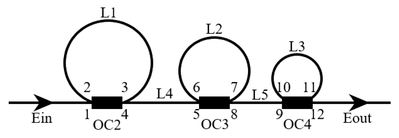
A directly linked three-coupler triple ring (DLTCTR) is used to enlarge the free spectral range (FSR), as shown in Figure 3. Accordingly, only one longitudinal mode could be selected to realize an SLM output.
Supposing that the least common multiple of the FSRs (effective FSR) for the three sub-rings is FSReff and that the lengths of the three sub-rings are L1, L2, and L3, then FSReff can be denoted as follows [17]:
F S R e f f = q 1 c n L 1 = q 2 c n L 2 = q 3 c n L 3
where q1, q2, and q3 are positive integers, n is the effective refractive index of the adopted optical fiber, and c represents the speed of light in a vacuum.
The transmission spectrum of the DLTCTR is then analyzed by the transfer matrix method. The transmission matrix of OC can be expressed as
T oc = 2 2 1 j j 1 ,
Supposing the optical field is injected into the DLTCTR through port 1 of the OC2,
E 1 = E i n ,
Furthermore, the optical fields at different ports of different OCs could be denoted as
E 3 E 4 = 2 2 1 γ i 1 1 i E 1 E 2
E 2 = E 3 · 1 δ · e α + i β · L 1 ,
E 5 = E 4 · 1 δ · e α + i β · L 4 ,
E 7 E 8 = 2 2 1 γ i 1 1 i E 5 E 6 ,
E 6 = E 7 · 1 δ · e α + i β · L 2 ,
E 9 = E 8 · 1 δ · e α + i β · L 5 ,
E 11 E 12 = 2 2 1 γ i 1 1 i E 9 E 10 ,
E 10 = E 11 · 1 δ · e α + i β · L 3 ,
E o u t = E 12 ,
where L1, L2, L3, L4, and L5 represent the length of the optical fiber, while δ, α, β, and γ are the fusion splicing loss, fiber loss coefficient, propagation constant, and insertion loss of the OC.
Finally, the transmittance T could be expressed by Eout and Ein, as shown below:
T = E o u t E i n E o u t E i n ,
Using MATLAB, the transmittance T could be simulated. In the simulation, the lengths of L1, L2, L3, L4, and L5 are 1, 0.36, 0.3, 0.4, and 0.5 m. The operating wavelength starts from 1945 nm to 1950 nm, and the obtained transmission spectrum is shown in Figure 4.
It should be noted that the presentation of Figure 4 in the manuscript is used to demonstrate whether this method of obtaining the transmittance of the DLTCTR is useful. Due to the high finesse of FSR for the DLTCTR filter, the optical spectrum analyzer (OSA) used in this experiment, with a resolution of 0.05 nm, is not suitable for the observation of the transmittance of the DLTCTR filter. However, the SLM output of the TDFL demonstrates the effectiveness of the DLTCTR filter. In future work, we will investigate how to observe the transmittance of the DLTCTR filter.

3. Experimental Setup

A schematic diagram of the proposed TDFL is depicted in Figure 5. It consists of a dual-active cavity structure, all-fiber polarization-rotation filtering structure, and a DLTCTR. The adopted optical devices are two LDs (LD1 and LD2), operating at 793 nm with a maximum output power of 12 W; two 793/2000 nm FCs; two sections of TDF, one with a length of 1.65 m (TDF1) and another with a length of 0.95 m (TDF2); four DI-PCs; two sections of PMF, one with a length of 1.65 m (PMF1) and another with a length of 1.63 m (PMF2); two polarizers; one isolator; six OCs with a coupling ratio of 50:50 (OC1, OC2, OC3, OC4, OC6, and OC7); and one OC with coupling ratio of 90:10 (OC5). The TDF 1 and 2 used in this experiment are the same type and have double cladding, and they are commercially available from NUFERN. The type used for TDF 1 and 2 is SM-TDF-10P/130-M. The producer of the OCs and the isolator is CSRayzer Optical Technology. First, 10% of the optical power in the laser cavity was extracted and input into OC6. Then, 50% of the intracavity optical power was input into the OSA (YOKOGAWA AQ6375E), 50% of the intracavity optical power was detected by the photodetector (PD, ET-5000F, Electro-Optics Technology, MI, USA), and the electrical signal was measured by the electrical spectrum analyzer (ESA, N9020A, Agilent, CA, USA).

4. Experimental Results

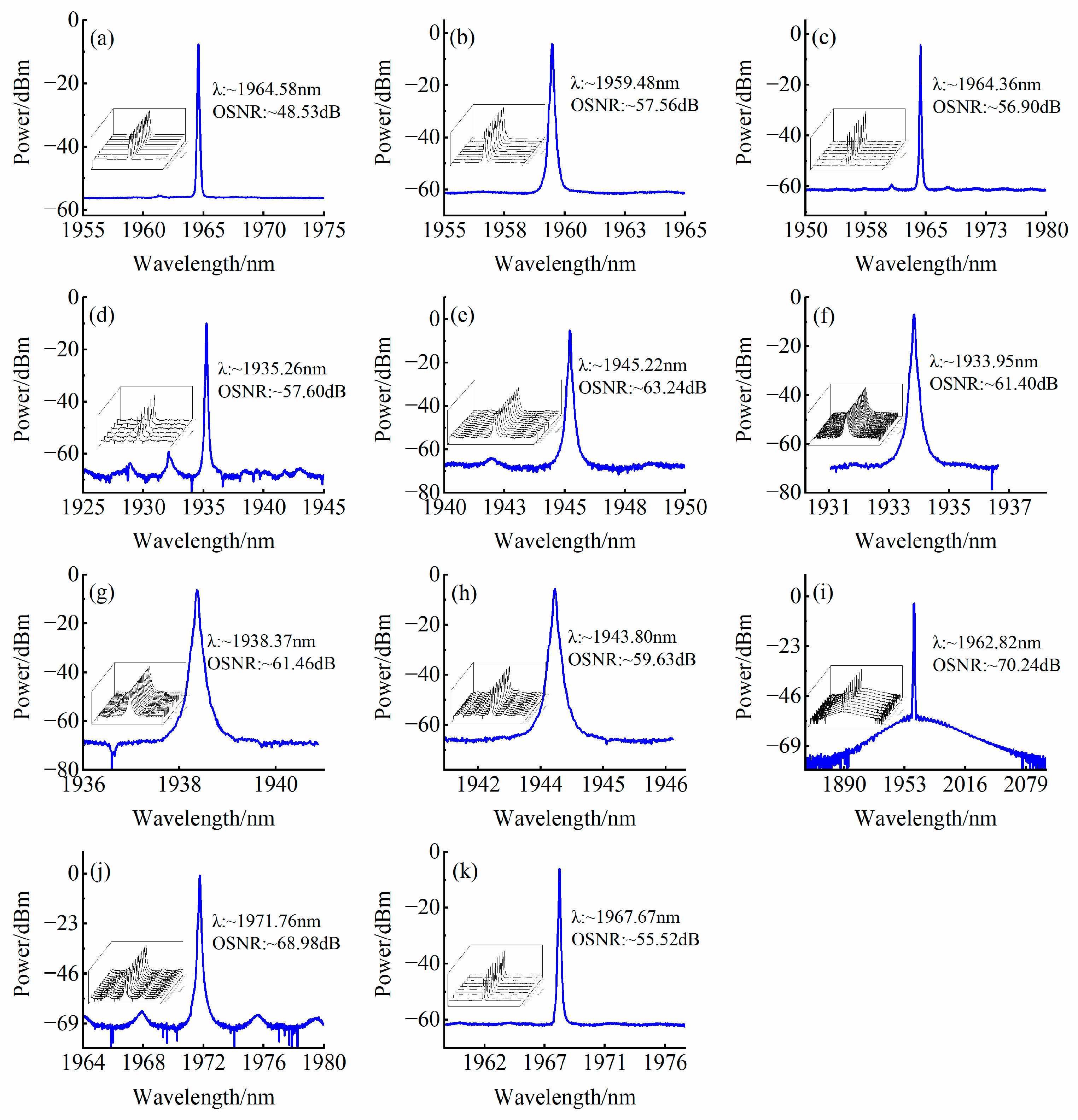
By adjusting the DI-PCs to balance the gain and loss inside the laser cavity, as well as adjusting the LDs one by one, optical spectra with different center wavelengths could be obtained. The output optical spectrum of the proposed wavelength-switchable SLM TDFL is shown in Figure 6. The center wavelengths of the eleven switchable outputs are 1967.66, 1964.58, 1959.48, 1964.36, 1935.26, 1945.22, 1933.95, 1938.37, 1943.80, 1962.82, and 1971.76 nm, and the switchable output wavelength range is up to 37.81 nm. The minimal wavelength interval is 0.22 nm. The optical signal-to-noise ratio (OSNR) in the entire wavelength tuning range is higher than 48.53 dB, and the maximal OSNR is 70.24 dB, which are satisfying output optical spectrum characteristics.
At room temperature, the proposed SLM TDFL was placed on an optical table. To be more specific, by adjusting the output power of the two pump sources and repeatedly adjusting the four DI-PCs, a single wavelength could be obtained. The relationship between the output center wavelength and the pump’s power is presented in Table 1. It should be noted that the operating temperature of the LD can affect the stability of the laser output. Thus, the operating temperature is also presented in Table 1. Therefore, by setting the pump power and DI-PC, the corresponding output center wavelength could be obtained. The stability of the eleven output wavelengths was tested and the testing time is also shown in Table 1. The different testing times mean that the eleven output wavelengths have different stable operating times (OTs). It can be seen from the results that λ5 (1935.26 nm) is the most unstable output, with a stable operating time of only 17 min, while λ7 (1933.95 nm) is the most stable output, with a stable operating time of 75 min. However, all the eleven output wavelengths are operating in an SLM state in the stable operating time, as shown in Table 1. During the experiment, the output power of the TDFL was less than 3 mW. Considering that the minimal pump power used in the experiment was 2028 mW, the optical conversion efficiency does not exceed 0.15%.
The output optical spectra of single-wavelength lasing with a center wavelength of 1964.58, 1959.48, 1964.36, 1935.26, 1945.22, 1933.95, 1938.37, 1943.80, 1962.82, 1971.76, and 1967.66 nm are shown in Figure 7. It can be seen that the OSNR varies from ~48.53 to 70.24 dB. This is because during the adjusting process of DI-PCs, the optical loss induced in the laser cavity is different for different center wavelengths, and this induces the different OSNRs of the output center wavelengths. The repeated records of the optical spectra are shown in the bottom left of every sub-figure, with a record interval of 3 min, under the corresponding testing time, as shown in Table 1 for every lasing wavelength. Obvious fluctuations of the center wavelength and output power were not found during the observation period.
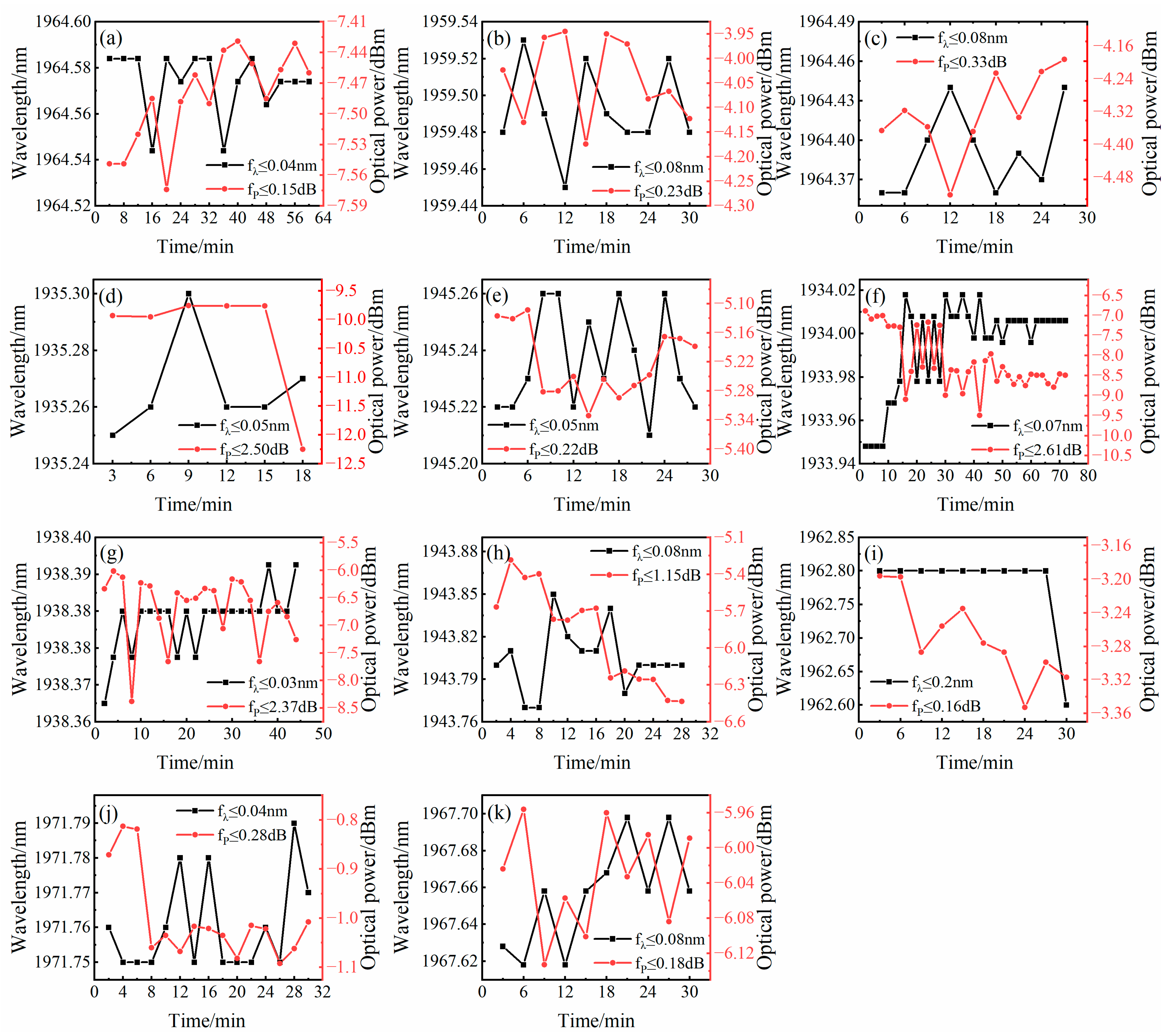
The detailed fluctuation with observation time of the output wavelength and output optical power for the eleven output optical spectra is shown in Figure 8. The fluctuation of the center wavelength is 0.03 nm, and the fluctuation of the output power varies from 0.15 to 2.61 dB, demonstrating a satisfying experimental result. The wavelength fluctuations are in some cases 200 pm (0.2 nm), and the minimal wavelength interval is 0.22 nm. Thus, the wavelength fluctuation is less than the minimum wavelength interval. The fluctuations of the center wavelength and output power originate from the fluctuation in the pump power, disturbance from the external environmental, the accumulated thermal effects of long-term pump operation, and mechanical vibrations. Thus, the proposed SLM TDFL could operate in a more stable state when carefully applying encapsulation, vibration isolation, and pump thermal management optimization. It should be noted that the OSNR is varying, and additional sidebands can appear in the emission spectra. Thus, an optical bandpass filter, such as an acousto-optic tunable bandpass filter, can be adopted to suppress the additional sidebands.
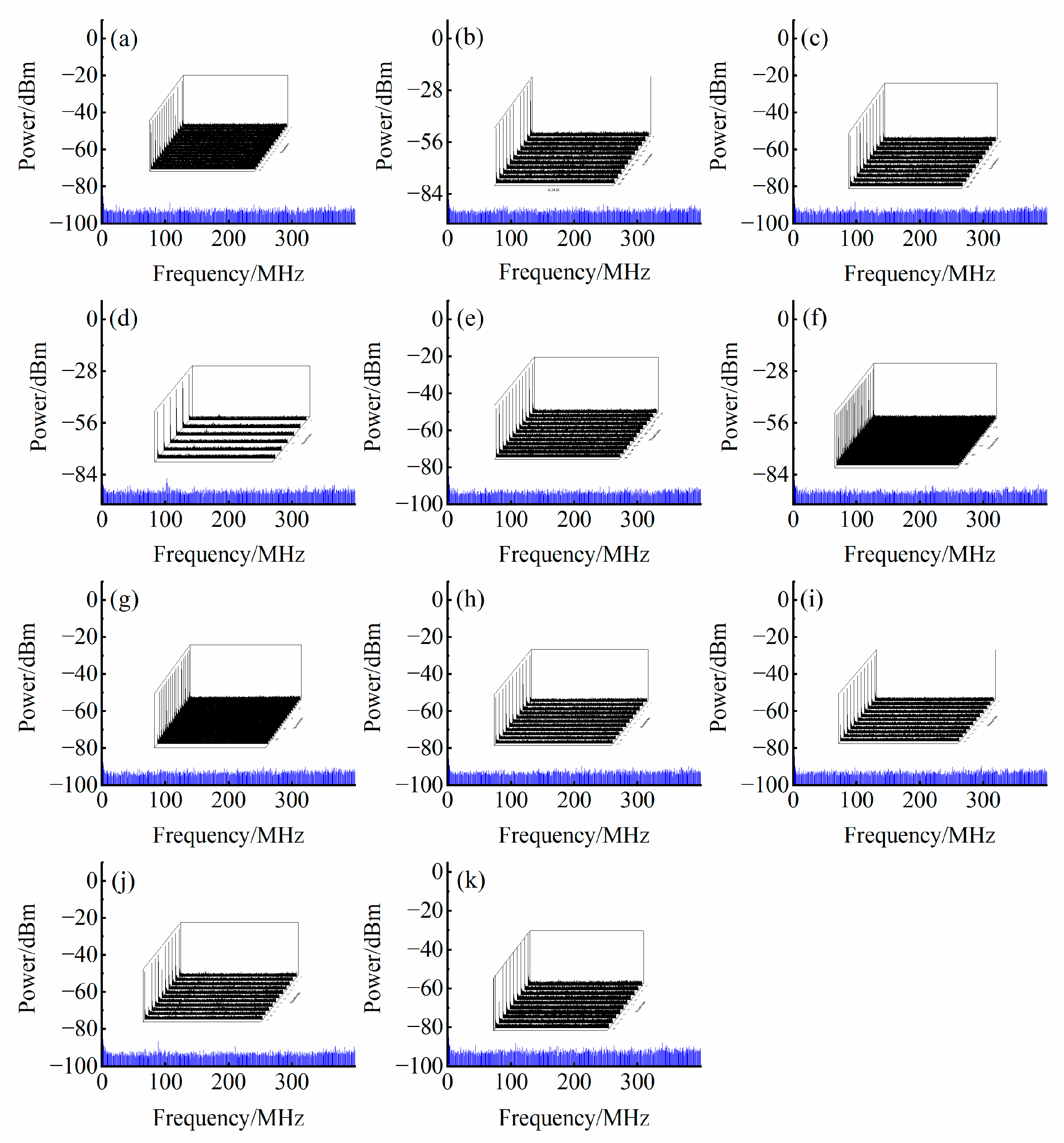
To verify whether the proposed TDFL is operating in an SLM state, the output optical signal, with an optical power of less than 3 mW, from the 50% output port of OC6 was input into a PD with a 12.5 GHz bandwidth to realize photoelectric conversion. The electrical signal was then fed into an ESA to observe the radio-frequency spectrum. In the experiment, the resolution bandwidth of the ESA was set to 20 kHz and the scanning range was set at 0 to 400 MHz. Mod-hopping was not found when the measurement was carried out, and the recorded radio-frequency spectra are shown in Figure 9 for the eleven output wavelengths. It can be observed from Figure 9 that non-zero frequency components are not found throughout the entire scanning frequency range, demonstrating that the proposed TDFL is operating in an SLM output state. To further verify the stability of its SLM operation, repeated scans of the detected radio-frequency spectrum were carried out with the testing times shown in Table 1, and the results are shown in the inset of Figure 9. Furthermore, non-zero frequency components were not observed in the observation period, demonstrating the stable SLM output of the proposed SLM TDFL.
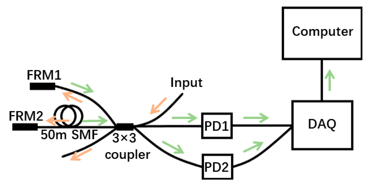
The laser linewidth of the eleven output wavelengths was measured using a homemade laser linewidth measurement system, as shown in Figure 10 [18,19,20]. The optical signal was input into one arm of the 3 × 3 optical coupler. Then, the optical signal was split into three parts. One part was reflected by a fiber-based Faraday rotator mirror, and the second part was transmitted through a section of single-mode fiber about 50 m in length and then reflected by another Faraday rotator mirror. The last part was input into a section of single-mode fiber which was coiled into small circles to attenuate its optical power. The reflected optical signals were then detected by two PDs (PD1 and PD2) with almost the same parameters. The converted electrical signal was then collected by a data acquisition card and further processed by a computer.
Specifically, the laser linewidth was calculated by the integration of the frequency noise’s power spectral density (PSD) under a certain frequency range (integration time), with the help of the β-separation line. The upper limit of the integration was the intersection point of the PSD and β-separation line, and the starting point for the integration was at the zero-frequency point. The measured PSDs for the eleven output laser wavelengths are shown in Figure 11, with the β-separation line also displayed. Thus, the laser linewidth could be obtained over different integration times.
The calculated laser linewidth values of the eleven output wavelengths are shown in Table 2. Overall, the variation in laser linewidth versus integration time exhibits the same tendency. That is, the laser linewidth increases with the increase in integration time. This is because the increased integration time, corresponding to a decreased lower limit of the integration bandwidth, led to an increased integration area, finally resulting in an increased laser linewidth. The laser’s output linewidth is less than 200 kHz under an integration time of 0.001 s for the eleven output wavelengths, and a minimal laser linewidth of 65.14 kHz was obtained. To further reduce the laser’s output linewidth, a linewidth-narrowing mechanism, such as self-injection locking or stimulated Brillouin scattering, should be considered.

5. Discussion

The proposed wavelength-switchable 2 μm SLM TDFL is compared with some reported in other works, and their key indicators are shown in Table 3. For Refs. [21,22,23], the proposed fiber lasers are working in the C band, while the fiber lasers in Refs. [24,25] and our work operate in the 2 μm waveband. The tuning mechanism in Ref. [23] is based on the tuning of an optical tunable filter, which is expensive. In Ref. [22], it is based on the tuning of a polarization controller (PC), which is more cost-effective. In Ref. [25], the output wavelengths are fixed. In our work, a switchable output is realized by the combination of a tuning PC and LD, which enables more output wavelengths, up to 11, which is more than in Refs. [21,22,23,24,25]. In addition, the range of switchable wavelengths output in our proposed work is 37.81 nm, which is 7.81 nm wider than that in Ref. [23]. The OSNR in this work is 70.24 dB, which is larger than that in Refs. [21,22,23,25] and smaller than that in Ref. [24]. The output power stability is in the mid-range of those in the other works. The stability of the output wavelength is worse than that in Refs. [22,23,24], which means that a stability mechanism for wavelength stabilization should be incorporated. As such, this will be investigated explicitly in future work. The output laser linewidth is wider than that in Refs. [21,22,23,24], indicating that a linewidth-narrowing mechanism should be used in future work.
It is reported that nanomaterials can be employed in a fiber laser to realize a pulsed laser output [26,27,28]. Thus, by using nanomaterials such as saturable absorbers in the proposed TDFL, an SLM and pulsed laser output can be obtained simultaneously, which is worth further investigation.

6. Conclusions

In conclusion, a wavelength-switchable 2 μm SLM TDFL was proposed and demonstrated. A dual-active cavity was used to provide gain for the laser output, and an all-fiber polarization-rotation structure was used to determine the operating wavelength. An SLM output was realized by using the DLTCTR filter, and a switchable-wavelength output was achieved by tuning the output power of the pump LD and the DI-PC simultaneously. Eleven switchable operating wavelengths, located at 1967.66, 1964.58, 1959.48, 1964.36, 1935.26, 1945.22, 1933.95, 1938.37, 1943.80, 1962.82, and 1971.76 nm, were obtained. A maximal OSNR of 70.24 dB was obtained. During the observation time, the minimal fluctuation of the center wavelength and output power was 0.03 nm and 0.15 dB, respectively. The measured radio-frequency spectra demonstrated that the proposed TDFL operated in a stable SLM state. In addition, a linewidth of 65.14 kHz was obtained under an integration time of 0.001 s. The proposed wavelength-switchable SLM TDFL is well suited to optical fiber communication and use in optical fiber sensing systems.

Author Contributions

Conceptualization, P.W. and Q.Q.; methodology, F.Y.; software, D.Y.; validation, C.Y. and J.H.; formal analysis, X.C.; investigation, D.X. and B.G.; resources, P.L.; data curation, Y.G.; writing—original draft preparation, P.W. and Q.Q.; writing—review and editing, P.W. and Q.Q.; visualization, P.W. and Q.Q.; supervision, F.Y. All authors have read and agreed to the published version of the manuscript.

Funding

This research was funded by the National Key Research and Development Program of China (2021YFB2800900); Key Program of the National Natural Science Foundation of China (62335001); and Natural Science Foundation of Henan Province (242300420701).

Data Availability Statement

The data presented in this study are available on request from the corresponding author due to legal reasons.

Conflicts of Interest

Author Biao Guan was employed by the company CRRC Technology Innovation (Beijing) Co., Ltd. The remaining authors declare that the research was conducted in the absence of any commercial or financial relationships that could be construed as a potential conflict of interest.

References

  1. Li, H.; Hu, F.; Li, C.; Tian, Y.; Huang, C.; Zhang, J.; Xu, S. Generation of switchable multiwavelength solitons with wide wavelength spacing at 2 μm. Opt. Lett. 2019, 44, 2442–2445. [Google Scholar] [CrossRef] [PubMed]
  2. Wu, M.; Li, X.; Wu, K.; Wu, D.; Dai, S.; Xu, T.; Nie, Q. All-fiber 2 μm thulium-doped mode-locked fiber laser based on MoSe2-saturable absorber. Opt. Fiber Technol. 2019, 47, 152–157. [Google Scholar] [CrossRef]
  3. Zhang, L.; Zhang, J.; Sheng, Q.; Sun, S.; Shi, C.; Fu, S.; Bai, X.; Fang, Q.; Shi, W.; Yao, J.-Q. Efficient multi-watt 1720 nm ring-cavity Tm-doped fiber laser. Opt. Express 2020, 28, 37910–37918. [Google Scholar] [CrossRef]
  4. Xu, K.; Li, H.; Liu, Y.; Wang, Y.; Tian, J.; Wang, L.; Du, J.; He, Z.; Song, Q. Optical fiber humidity sensor based on water absorption peak near 2-μm waveband. IEEE Photonics J. 2019, 11, 7101308. [Google Scholar] [CrossRef]
  5. Geng, J.; Wang, Q.; Lee, Y.; Jiang, S. Development of eye-safe fiber lasers near 2 μm. IEEE J. Sel. Top. Quantum Electron. 2014, 20, 150–160. [Google Scholar] [CrossRef]
  6. Kalaycıoğlu, H.; Elahi, P.; Akçaalan, Ö.; Ilday, F.O. High-repetition-rate ultrafast fiber lasers for material processing. IEEE J. Sel. Top. Quantum Electron. 2017, 24, 8800312. [Google Scholar]
  7. Walasik, W.; Traoré, D.; Amavigan, A.; Tench, R.E.; Delavaux, J.-M.; Pinsard, E. 2-μm narrow linewidth all-fiber DFB fiber Bragg grating lasers for Ho-and Tm-doped fiber-amplifier applications. J. Light. Technol. 2021, 39, 5096–5102. [Google Scholar] [CrossRef]
  8. Kapasi, D.P.; Eichholz, J.; McRae, T.; Ward, R.; Slagmolen, B.J.J.; Legge, S.; Hardman, K.S.; Altin, P.A.; McClelland, D.E. Tunable narrow-linewidth laser at 2 μm wavelength for gravitational wave detector research. Opt. Express 2020, 28, 3280–3288. [Google Scholar] [CrossRef]
  9. Chen, Y.; Yao, B.; Liu, H.; Wei, S.; Mao, Q. Development of single-longitudinal-mode DBR fiber laser based on thulium-doped silica glass fiber. Chin. J. Quantum Electron. 2023, 40, 56–61. [Google Scholar]
  10. Zamzuri, A.K.; Ariannejad, M.M.; Samion, M.Z.; Tan, C.; Ismail, M.; Bayang, L.; Ahmad, H. Narrow bandwidth optimization using a polymer microring resonator in a thulium–holmium fiber laser cavity. Opt. Commun. 2020, 466, 125574. [Google Scholar] [CrossRef]
  11. Budarnykh, A.E.; Vladimirskaya, A.D.; Lobach, I.A.; Kablukov, S.I. Broad-range self-sweeping single-frequency linearly polarized Tm-doped fiber laser. Opt. Lett. 2018, 43, 5307–5310. [Google Scholar] [CrossRef] [PubMed]
  12. Hu, K.; Kabakova, I.V.; Lefrancois, S.; Hudson, D.D.; He, S.; Eggleton, B.J. Hybrid Brillouin/thulium multiwavelength fiber laser with switchable single-and double-Brillouin-frequency spacing. Opt. Express 2014, 22, 31884–31892. [Google Scholar] [CrossRef] [PubMed]
  13. Sadiq, M.U.; Zhang, H.; O’Callaghan, J.; Roycroft, B.; Kavanagh, N.; Thomas, K.; Gocalinska, A.; Chen, Y.; Bradley, T.; Hayes, J.R.; et al. 40 Gb/s WDM transmission over 1.15-km HC-PBGF using an InP-based Mach-Zehnder modulator at 2 μm. J. Light. Technol. 2016, 34, 1706–1711. [Google Scholar] [CrossRef]
  14. Qin, Q.; Li, T.; Yan, F.; Feng, T.; Sun, W.; Han, W.; Yang, D.; Wang, X.; Yu, C.; Wang, P.; et al. Demonstration of the first outdoor 2-μm-band real-time video transmission free-space optical communication system using a self-designed single-frequency fiber laser. J. Light. Technol. 2023, 41, 5275–5283. [Google Scholar] [CrossRef]
  15. Wang, W.; Meng, H.Y.; Wu, X.W.; Xiong, R.; Xue, H.C.; Tan, C.H.; Huang, X.G. A nonlinear polarization rotation-based linear cavity waveband switchable multi-wavelength fiber laser. Laser Phys. Lett. 2012, 10, 015104. [Google Scholar] [CrossRef]
  16. Tang, M.; Jiang, Y.; Li, H.; Zhao, Q.; Cao, M.; Mi, Y.; Jian, W.; Ren, W.; Ren, G. Multi-wavelength fiber laser based on dual-Sagnac comb filter for LP 11 modes output. J. Light. Technol. 2020, 38, 3745–3750. [Google Scholar] [CrossRef]
  17. Wang, Z.; Shang, J.; Xu, Y.; Qiao, Y.; Yu, S. Stable narrow-linewidth single-longitudinal mode laser by exploiting double subring resonator and self-injection loop. Opt. Fiber Technol. 2022, 68, 102775. [Google Scholar] [CrossRef]
  18. Yang, D.; Yan, F.; Feng, T.; Qin, Q.; Li, T.; Yu, C.; Wang, X.; Jiang, Y.; Kumamoto, K.; Suo, Y. Stable narrow-linewidth single-longitudinal-mode thulium-doped fiber laser by exploiting double-coupler-based double-ring filter. Infrared Phys. Technol. 2023, 129, 104568. [Google Scholar] [CrossRef]
  19. Tan, H.; Yan, F.; Feng, T.; Li, T.; Qin, Q.; Yang, D.; Guo, H.; Wang, X.; Wu, G.; Cai, Y.; et al. Highly stable single-longitudinal-mode erbium-doped fiber laser using dual-ring compound cavity filter and saturable absorber. Opt. Fiber Technol. 2024, 83, 103655. [Google Scholar] [CrossRef]
  20. Yang, D.; Yan, F.; Guo, Y.; Qin, Q.; Li, T.; Yu, C.; Wang, X.; Guo, H.; Cai, Y.; Ji, W.; et al. Suppression of intensity noise and phase noise for thulium-holmium co-doped fiber laser by self-injection locking. Opt. Express 2024, 32, 33521–33530. [Google Scholar] [CrossRef]
  21. Chen, H.; Yang, J.; Song, S.; Long, B. Compound four-cavity single-longitudinal mode fiber laser. Opt. Express 2024, 32, 7079–7089. [Google Scholar] [CrossRef] [PubMed]
  22. Wang, Z.; Wei, J.K.; Chen, P.C.; Liaw, S.-K.; Chen, J.-K.; Yeh, C.-H. Eight-Wavelength Selectable Single-Longitudinal-Mode Fiber Laser Using 1 × 8 Arrayed Waveguide Grating and Passive Triple Subring Resonators. IEEE Photonics J. 2024, 16, 7101407. [Google Scholar] [CrossRef]
  23. Tao, L.; Wang, F.; Wu, Z.; Xia, G. Stable and Tunable PT-Symmetric Single-Longitudinal-Mode Fiber Laser Using a Nonreciprocal Sagnac Loop. IEEE Access 2023, 11, 23127–23135. [Google Scholar] [CrossRef]
  24. Huang, Q.; Yan, F.; Feng, T.; Yang, D.; Li, T.; Tan, H.; Peng, S.; Guo, H.; Wang, X. High OSNR single-longitudinal-mode thulium-doped fiber laser based on a cascaded dual-ring cavity filter. Infrared Phys. Technol. 2024, 140, 105417. [Google Scholar] [CrossRef]
  25. Soltanian, M.R.K.; Ahmad, H.; Khodaie, A.; Amiri, I.S.; Ismail, M.F.; Harun, S.W. A stable dual-wavelength Thulium-doped fiber laser at 1.9 μm using photonic crystal fiber. Sci. Rep. 2015, 5, 14537. [Google Scholar] [CrossRef]
  26. Sun, J.; Cheng, H.; Xu, L.; Fu, B.; Liu, X.; Zhang, H. Ag/MXene composite as a broadband nonlinear modulator for ultrafast photonics. ACS Photonics 2023, 10, 3133–3142. [Google Scholar] [CrossRef]
  27. Fu, B.; Sun, J.; Wang, C.; Shang, C.; Xu, L.; Li, J.; Zhang, H. MXenes: Synthesis, optical properties, and applications in ultrafast photonics. Small 2021, 17, 2006054. [Google Scholar] [CrossRef]
  28. Zhao, X.; Jin, H.; Liu, J.; Chao, J.; Liu, T.; Zhang, H.; Wang, G.; Lyu, W.; Wageh, S.; Al-Hartomy, O.A.; et al. Integration and applications of nanomaterials for ultrafast photonics. Laser Photonics Rev. 2022, 16, 2200386. [Google Scholar] [CrossRef]
Figure 1. Dual-active cavity. LD: laser diode; FC: fiber combiner; TDF: thulium-doped fiber; OC: optical coupler; ISO: isolator.
Photonics 11 01031 g001
Figure 2. All-fiber polarization-rotation filtering structure. DI-PC: drop-in polarization controller; PMF: polarization-maintaining fiber; Pol: polarizer; OC: optical coupler.
Photonics 11 01031 g002
Figure 3. Directly linked three-coupler triple ring.
Photonics 11 01031 g003
Figure 4. Simulated transmission spectrum of the DLTCTR filter.
Photonics 11 01031 g004
Figure 5. Experimental setup of the proposed TDFL.
Photonics 11 01031 g005
Figure 6. Output optical spectrum of the proposed SLM TDFL. Different color lines mean different wavelength outputs.
Photonics 11 01031 g006
Figure 7. Output optical spectrum of single-wavelength lasing with a center wavelength of (a) 1964.58, (b) 1959.48, (c) 1964.36, (d) 1935.26, (e) 1945.22, (f) 1933.95, (g) 1938.37, (h) 1943.80, (i) 1962.82, (j) 1971.76, or (k) 1967.66 nm. Subfigures are the repeated records of the output spectra.
Photonics 11 01031 g007
Figure 8. Fluctuation of output laser power and center wavelength with a center wavelength of (a) 1964.58, (b) 1959.48, (c) 1964.36, (d) 1935.26, (e) 1945.22, (f) 1933.95, (g) 1938.37, (h) 1943.80, (i) 1962.82, (j) 1971.76, or (k) 1967.66 nm.
Photonics 11 01031 g008
Figure 9. Radio-frequency spectra of (a) 1964.58, (b) 1959.48, (c) 1964.36, (d) 1935.26, (e) 1945.22, (f) 1933.95, (g) 1938.37, (h) 1943.80, (i) 1962.82, (j) 1971.76, or (k) 1967.66 nm. Subfigures are the repeated records of the output radio-frequency spectra.
Photonics 11 01031 g009
Figure 10. Laser linewidth measurement system. FRM: Faraday rotator mirror; SMF: single-mode fiber; PD: photodetector; DAQ: data acquisition card.
Photonics 11 01031 g010
Figure 11. Frequency-noise power spectral density of (a) 1964.58, (b) 1959.48, (c) 1964.36, (d) 1935.26, (e) 1945.22, (f) 1933.95, (g) 1938.37, (h) 1943.80, (i) 1962.82, (j) 1971.76, or (k) 1967.66 nm, and the β-separation line.
Photonics 11 01031 g011
Table 1. The relationship between the output center wavelength and the pump power and operating temperature of the pump source.
Wavelength/nmLD1LD2Testing Time/minWhether It Is in an SLM State
Pump
Power/mW
OT/°CPump
Power/mW
OT/°C
λ1: 1967.66202823.8//30Y
λ2: 1964.58204828//60Y
λ3: 1959.48235524.9//30Y
λ4: 1964.36235224.4//27Y
λ5: 1935.26//6338.528.417Y
λ6: 1945.22//636124.730Y
λ7: 1933.95//6347.825.875Y
λ8: 1938.37//6355.727.242Y
λ9: 1943.80//6764.228.630Y
λ10: 1962.82235227.61319.028.530Y
λ11: 1971.763193.625.8//30Y
Table 2. The calculated laser linewidths of the eleven output wavelengths under different integration times.
Integration Time (s)0.0010.0050.010.050.10.2
Δv1 (kHz) 91.821.25 × 1032.78 × 10335.89 × 103109.10 × 103811.80 × 103
Δv2 (kHz)85.840.63 × 1031.85 × 10320.56 × 10368.70 × 103248.00 × 103
Δv3 (kHz)72.550.93 × 1032.87 × 10338.71 × 103167.80 × 103870.00 × 103
Δv4 (kHz)113.681.6 × 1034.38 × 10368.86 × 103467.40 × 1031128.000 × 103
Δv5 (kHz)171.596.10 × 10322.25 × 10322.29 × 10322.33 × 10322.42 × 103
Δv6 (kHz)65.140.67 × 1032.22 × 10322.29 × 103200.30 × 103503.30 × 103
Δv7 (kHz)72.740.64 × 1032.02 × 10318.70 × 10377.75 × 103581.4 × 103
Δv8 (kHz)186.834.441 × 10315.65 × 10315.70 × 10315.80 × 10316.46 × 103
Δv9 (kHz)174.365.88 × 10322.09 × 10322.12 × 10322.17 × 10322.25 × 103
Δv10 (kHz)167.327.07 × 10327.54 × 10327.56 × 10327.59 × 10327.72 × 103
Δv11 (kHz)173.731.92 × 1036.68 × 10310.99 × 103435.90 × 1031860.00 × 103
Table 3. Comparison of the SLM TDFL in this work with some in reported works in terms of some key indicators.
Operating WavebandTuning
Mechanism
Number of WavelengthsSwitchable
Output Range (nm)
OSNRPower
Stability
(dB)
Wavelength
Stability
(nm)
Linewidth (kHz)Ref
C band/1/650.28/0.25[21]
C bandTuning PC85.63~600.010.0052.5[22]
C bandOTF/30432.420.0060.68[23]
2 μm waveband/1/~75.100.6850.0111.82[24]
1.9 μm wavebandNA2NA451NANA[25]
2 μm wavebandTuning PC and LD1137.81~70.240.150.0365This work
Disclaimer/Publisher’s Note: The statements, opinions and data contained in all publications are solely those of the individual author(s) and contributor(s) and not of MDPI and/or the editor(s). MDPI and/or the editor(s) disclaim responsibility for any injury to people or property resulting from any ideas, methods, instructions or products referred to in the content.