Communication

Analysis on Reducing the Bandwidth of Kelly Sidebands in Mode-Locking Fiber Laser for Narrow Terahertz Signal Generation

1
School of Science, Jiangsu University of Science and Technology, Zhenjiang 212100, China
2
Institute of Applied Photonic Technology, Yangzhou University, Yangzhou 225002, China
*
Author to whom correspondence should be addressed.
Photonics 2024, 11(12), 1124; https://doi.org/10.3390/photonics11121124
Submission received: 18 October 2024 / Revised: 13 November 2024 / Accepted: 25 November 2024 / Published: 27 November 2024
(This article belongs to the Section Lasers, Light Sources and Sensors)

Abstract

:
The bandwidth of the ±1-order Kelly sidebands of mode-locking fiber lasers is investigated for narrow terahertz (THz) signal generation. Four key factors influencing the bandwidth of Kelly sidebands are found and analyzed in detail. Then, a numerical model is presented for manipulating the parameters of the mode-locking fiber laser. Two mode-locking fiber lasers are designed for generating narrow sidebands. The bandwidth of the ±1-order Kelly sidebands is reduced to 0.041 nm and 0.021 nm for the sidebands with different spacings. Using the data obtained from the optical spectra with narrow bandwidth Kelly sidebands, the frequency spectra of the generated THz signals are obtained. Finally, the bandwidth of the generated THz signals is reduced to 7.16 GHz and 3.4 GHz, respectively.

1. Introduction

In recent years, there has been a significant surge in the development of laser-based terahertz (THz) sources. This is being driven by versatile applications including spectroscopy [1], femtosecond X-ray pulse characterization [2,3], terahertz communications [4,5], etc. Considerable efforts have been taken to generate broadband and narrowband THz signals [6,7,8]. Compared with pulse shaping technology [9], photo-mixing can offer a cost-effective and convenient way to generate narrow-bandwidth terahertz waves [10]. The linewidth of generated narrowband THz wave can be well defined with suitable laser sources.
Using two tunable distribution feedback diode lasers or dual-wavelength fiber lasers to pump a photomixer, narrowband THz signals can be obtained [11]. The disadvantage is that uncorrelated phase noise from lasers can seriously reduce the quality of generated THz signals. In comparison, the use of a mode-locked fiber laser to generate stable THz signals can be a promising method due to the mode-locking mechanism and consequent stability. A technique using two filtered longitudinal modes with proper wavelength intervals from a mode-locked semiconductor laser or a fiber laser has been reported for THz signal generation [12], while the external filter in this method increases the complexity of the system. In our previously reported technique, which utilizes the ±1-order Kelly sidebands of mode-locked fiber lasers and photomixing for generating terahertz signals, several advantages have been demonstrated for good tunability [13] and high-intensity sidebands [14]. The bandwidth of the ±1-order Kelly sideband exceeds 10 GHz in refs. [13,15]. It is desirable for the bandwidth of the ±1-order Kelly sidebands to be narrower for photomixing, so that the generated THz signals can have a small bandwidth, which is required for many practical applications. Previous studies on the spectral properties of Kelly sidebands in soliton fiber lasers have focused on their spacing and intensity [16,17]; their bandwidth is rarely explored systematically. The research presented in this paper provides a new model and a new technical way to generate terahertz signals with a narrow bandwidth by exploring the mechanism of reducing the sideband bandwidth.
In this report, narrow THz signal generation by reducing the bandwidth of the ±1-order Kelly sidebands of mode-locked fiber lasers is investigated. This is carried out through exploring the influence factors of the Kelly sideband and optimizing parameters of soliton mode-locking fiber lasers. Four key factors related to the bandwidth of the Kelly sidebands are found and analyzed. A numerical model is presented for manipulating the parameters to design the mode-locking fiber laser so that bandwidth-narrowed sidebands can be achieved. Consequently, the frequency spectra of the generated narrow terahertz signals are worked out.

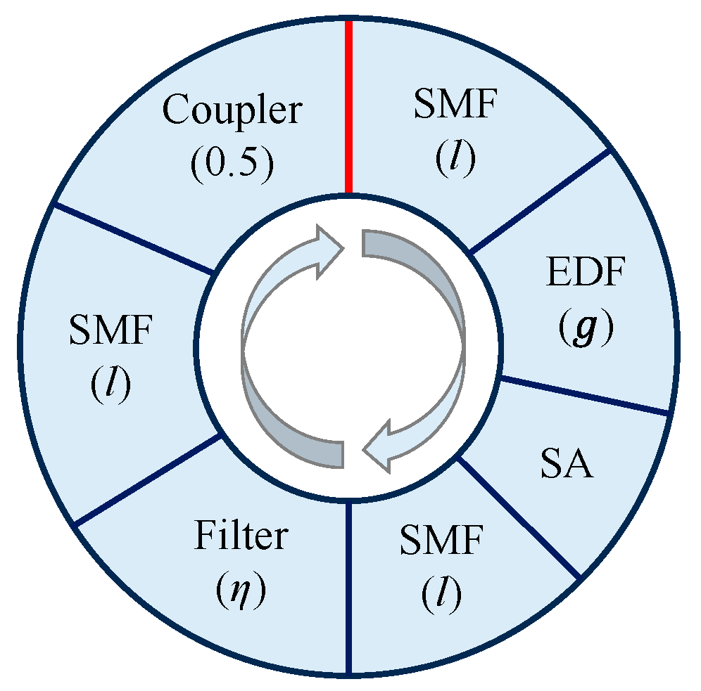
2. Model of the Bandwidth of Kelly Sidebands

When a soliton optical pulse circulates in a mode-locking fiber laser, the pulse essentially experiences its average state plus some weak periodic disturbance brought about by the discrete nature of gain, loss, dispersion, and nonlinearity. These perturbations can lead to the emission of dispersive waves from the soliton [18,19]. Then, the soliton resonantly couples with a copropagating dispersive wave. The quasi-matching between their relative phases results in constructive interference, with multiple pairs of sharp spectral peaks added to the soliton’s spectrum.
Although the analytical model for the bandwidth of the Kelly sideband is given in ref. [20], the detailed derivation is not presented. In order to derive it, we start from Equation (6) in ref. [20]. The coefficient K in front of the sideband waveform φ b is equal to
K = l g ψ 1 + η t 2 = l g + g η ω n 2
where the operator t is presented as i ω n in the Fourier frequency domain. K is the rate term and represents the rate of exponential decay or growth of the sideband amplitude. ω n is the peak frequency of the n-order sideband. Ψ is the entire waveform. l is the signal loss and g[ Ψ ] is the overall gain coefficient. η is the coefficient of spectral filtering. In addition, it is known that the term i K n φ b in the normalized nonlinear Schrodinger equation (NLSE) can be treated as the perturbation term [21], where K n is the normalized rate term and K n = K / ω n . In laser physics, the spectral width, which measures how rapidly the sideband amplitude decays to half its maximum value, is half of the imaginary part of the growth rate [22]. So, the bandwidth of the +1-order Kelly sideband δω equals K n / 2 ; that is,
δ ω = l + g η ω 1 2 1 / 2 ω 1
where ω 1 is the normalized frequency position of the +1-order Kelly sideband. This model shows that by adjusting parameters l , g, η, the bandwidth of +1-order sideband can be changed. Moreover, it is evident that δω will be increased with an increase in loss l . Due to the product of g and η, the influence of g and η on δω requires investigation in detail by simulation. In addition, as the intra-cavity dispersion of the laser broadens the sideband in the time domain [23] and thus obviously affects the δω, this parameter is also investigated by simulation in the following section.
In order to establish the relationship between the above normalized parameters and the parameters of a real mode-locking laser, the extended NLSE including a set of laser parameters is used. The spectra with the Kelly sideband of a mode-locked fiber laser, and consequently, the sideband width, can be quantitatively analyzed. The simulation model is schematically shown in Figure 1. The ring cavity consists of a piece of erbium-doped fiber (EDF), three pieces of single-mode fiber (SMF), a super-Gaussian-shaped filter, an output coupler with a splitting ratio of 50%, and a saturable absorber. The saturable absorber is assumed to be a semiconductor saturable absorber mirror (SESAM). The simulation parameters are shown in Table 1, where all fibers in the ring are assumed to have the same nonlinear coefficient, 3.3 W−1 km−1. In addition, the peak reflection of the filter is set to 1. The coefficient of spectral filtering η is related to the bandwidth of filter B W F . The total dispersion of the laser is adjusted by changing the dispersion parameter of SMF (defined as D S M F ). The total loss L of the laser is averaged over the SMF during simulation for simplification, although the loss of practical SMF at 1550 nm is very small. The net gain G is determined by the gain function of the EDF, which is expressed as
G = G 0 / 1 + E p / E g
where E g is the gain saturation energy and is dependent on the pump power. E p is the pulse energy, and G0 is the small-signal gain coefficient. The extended NLSE describing the pulse propagating in the laser cavity can be expressed as
E z + i β 2 2 2 E t 2 G 2 E G 2 Ω G 2 2 E t 2 = i γ E 2 E
where E is the electric field amplitude of the slowly varying pulse envelope. β 2 is the second-order dispersion. Ω G is the bandwidth of the gain, and γ is the nonlinear coefficient. The symmetric split-step Fourier method is implemented in the simulation. The simulation starts with arbitrary white noise and converges into a stable state solution for mode-locked pulses formed after approximately 500 cycles of integration.

3. Key Factors Affecting Kelly Sideband Bandwidth
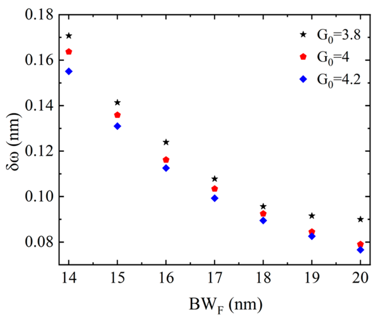
A simulation has been conducted to explore and confirm the quantitative relationships between the key factors and the sideband bandwidth. It is noted that the full width at half maximum (FWHM) of the +1-order sidebands is defined as the sideband bandwidth δω.

3.1. Influences of Filtering Bandwidth B W F on Bandwidth δω

The relationship between the bandwidth of filter B W F and sideband bandwidth δω is investigated. Suitable values of gain G0, loss L, and dispersion D S M F are firstly chosen. Then, the filter bandwidth B W F is changed within a suitable range while keeping the stability of the optical spectrum with the Kelly sidebands. It can be seen in Figure 2 that when B W F increases from 14 nm to 20 nm, δω decreases for the different small-signal gain coefficient G0. The minimum δω is approximately 0.08 nm. In addition, more simulation results show that when G0 is 3.8, increasing the B W F to more than 20 nm does not significantly change the sideband width δω. This can also be seen from Figure 2. With B W F increasing, the change in black star points gradually slows down. In this case, further increasing B W F will not obviously reduce δω. Instead, the gain and loss can be used to reduce the δω value further.
As the ±1-order Kelly sidebands are located on both sides of the central spectrum, the spectral filtering effect leads to changes in the bandwidth and intensity of the sideband simultaneously. When G0 is 3.8 and L is 9 dB, the optical spectra are calculated for four different B W F values and shown in Figure 3a. As the B W F increases, the intensity of the +1-order Kelly sideband gradually increases from −9.4 dB to −5 dB, while the sideband bandwidth δω is reduced from 0.17 nm to 0.09 nm, as shown in Figure 3b. Compressing the sideband bandwidth δω by increasing B W F can be explained as follows. Increasing the bandwidth of the filter causes the central soliton spectrum to broaden. Since the time–bandwidth product of central soliton remains nearly constant at around 0.315, the pulse width of soliton is compressed. As the dispersive wave is a pedestal with an exponentially decaying envelope centered at the pulse, with the soliton pulse width reducing, this is equivalent to an increase in the temporal width of dispersive waves. Due to the characteristic of maintaining a Lorentz shape in the sidebands, the bandwidth of the Kelly sideband consequently decreases.

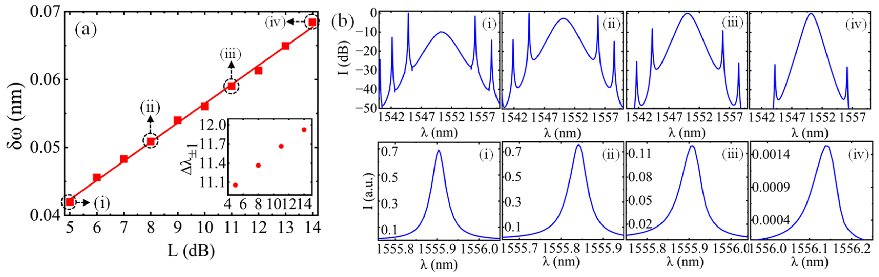
3.2. Influences of Gain Coefficient G0 and Loss L on Bandwidth δω

In order to reduce the bandwidth of the sidebands further, the bandpass filter is removed. The bandpass filtering effect of the laser cavity only comes from the gain bandwidth of EDF, which is about 50 nm. Such a large filtering bandwidth has little effect on δω. Then, the influence of the gain coefficient G0 and loss L on δω are explored. When the loss L is 10 dB and D S M F is 35 ps/(nm·km), an increase in G0 from 3.2 to 5.7 results in a decrease in δω from 0.063 nm to 0.046 nm, as shown in Figure 4. In addition, when the gain G0 is 4 and D S M F is 35 ps/(nm·km), with L increasing from 5 dB to 14 dB, δω increases from 0.042 nm to 0.069 nm, as shown in Figure 5. It is obvious that increasing G0 or reducing L has a similar effect in reducing δω. In addition, compared with the four optical spectra shown in Figure 4b and Figure 5b, it is found that increasing G0 or reducing L leads to an increase in the intensity of the +1-order sideband, which is attributed to the enhanced nonlinear effect of the laser cavity [14].

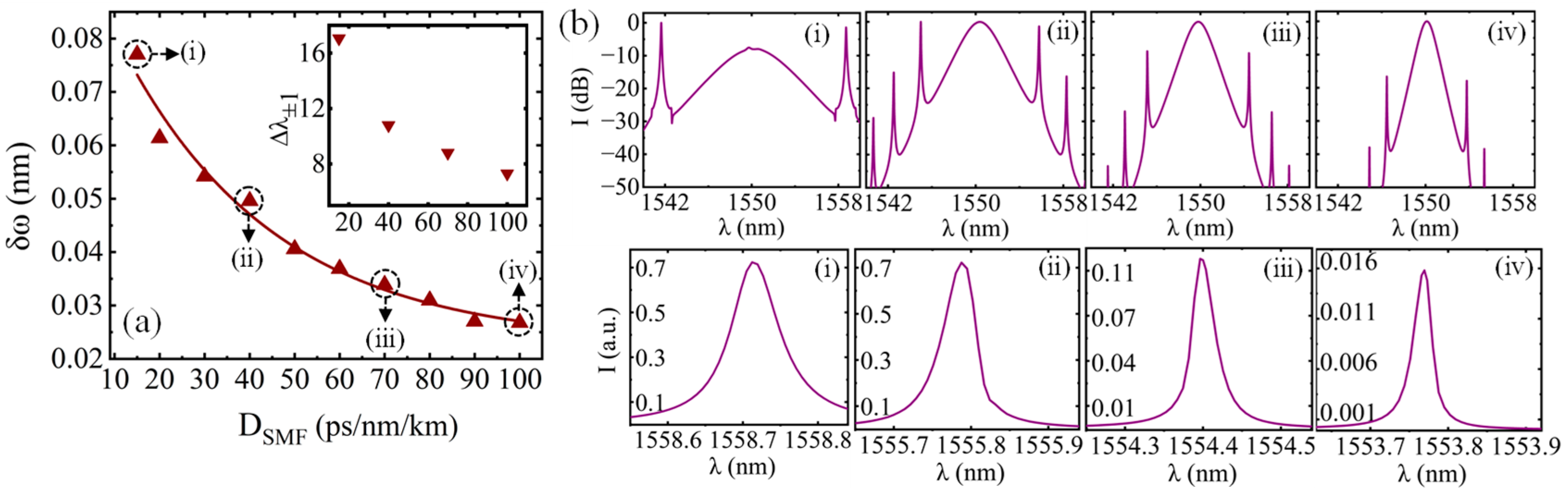
3.3. Influences of Dispersion Parameter D S M F on Bandwidth δω

In order to investigate the influences of dispersion on sideband bandwidth by changing the D S M F , the relationship between D S M F and δω is shown in Figure 6a. It can be seen that with D S M F increasing from 10 ps/(nm.km) to 100 ps/(nm.km), δω decreases from 0.077 nm to 0.027 nm. This indicates that increasing dispersion is beneficial in reducing the sideband bandwidth δω. Since the increase in dispersion leads to the broadening of the dispersive wave in the time domain, the bandwidth of the sideband is decreased accordingly. In addition, by comparing the four optical spectra in Figure 6b, it is found that the change in dispersion influences not only the sideband intensity but also the spacing of the ±1-order sidebands. It is known that there is an inverse square root dependence of the spacing of ±1-order Kelly sidebands on the dispersion of the laser cavity [13]. Thus, for sidebands with large spacing, the minimal bandwidth is larger than that of sidebands with small spacing. This implies that the minimum bandwidth of a sideband is dispersion-dependent.
In addition, inspecting the three insert figures from Figure 4, Figure 5 and Figure 6, it can be seen that the spacing of the ±1-order sidebands ∆λ±1 is reduced with decease in δω. As ∆λ±1 is related to the pulse width, the slight change in ∆λ±1 is due to the change in soliton pulse width brought by gain G0 and loss L. In comparison, dispersion D S M F changes the spacing more significantly, as shown by the inset figure in Figure 6. It also means that the minimal bandwidth of Kelly sidebands with different spacing is different.

4. Terahertz Signal Generation by Bandwidth-Narrowed Kelly Sidebands

Considering practical applications, narrow-bandwidth and high-intensity Kelly sidebands with specified spacing are required. Based on the above analysis and simulation, two well-designed mode-locking fiber lasers are proposed to achieve bandwidth-narrowed Kelly sidebands under different sideband spacings. The filtering device is excluded from the laser cavity, and the loss of the laser cavity is reduced as much as possible. An appropriate dispersion value for the laser cavity is chosen based on the required THz signal frequency. Then, the gain increases gradually while keeping the spectrum stable, finally resulting in narrow and strong Kelly sidebands.
The spectra of two mode-locked fiber lasers are shown in Figure 7. It can be seen that both spectra combine wide spacing, high intensity, and a narrow bandwidth. The spacings of the ±1-order sidebands for two spectra are 11.1 nm and 6.8 nm, respectively, caused by the different values of D S M F . The losses of two lasers are set to 4.6 dB. With the increase in the gain G0 to 4 and 7, the sideband bandwidth reduces to 0.041 nm and 0.021 nm, respectively. These values are believed to be almost the smallest achievable after taking the sideband stability and intensity into account. For both spectra, the intensity of the ±1-order Kelly sideband exceeds 10 dB of the peak intensity of the central soliton. Furthermore, comparing the two spectra, it is evident that for the sideband with large spacing, the minimum sideband bandwidth is larger than that of the sideband with small spacing.
It is worth mentioning the temporal characteristics of the ±1-order Kelly sidebands, as the time delays of the two sidebands can affect the experimental design and results. According to the report [24], the ±1-order Kelly sidebands are partly temporally overlapped. This can be understood through the influence of dispersion on the sidebands. It is known that dispersion of the laser cavity related to the optical frequency can lead to a time delay in different spectral elements. That is, signals with different frequencies experience different time delays when they circulate in the laser cavity. Because the two Kelly sidebands have a relatively large frequency difference, they have delays in the time domain. We can use a method similar to that detailed in Ref. [25] to generate THz signals, but the experimental system needs to be changed to compensate for the time delay. The optical pulse can be divided into two paths. Then, one of the paths uses an optical delay line to compensate for the delay. In principle, when the optical pulse containing the Kelly sidebands illuminates the photoconductive antenna (PCA), any two longitudinal modes in the optical spectrum mix with each other and then the full-frequency spectrum can be obtained. The radiated THz field is proportional to the photocurrent, while the photocurrent depends on the power of optical pulse and the optical response of PCA. The THz signal mixed by the ±1-order Kelly sidebands can be found in the frequency spectrum. It is noted that practical THz signal measurement is not available at the moment due to the equipment limitations for experiments.
THz signals can be produced by heterodyning the two wavelength components in the laser spectrum. The generated THz signal is equivalent to the wavelength spacing of the two optical waves (E1 and E2), which have the following electronic fields:
E 1 ω = E 1 exp j 2 π ω 1 t + ϕ 1
E 2 ω = E 2 exp j 2 π ω 2 t + ϕ 2
It should be noted that the intensity of the wave beating can be explained by Equation (7), below. Here, ω is the angular frequency, t is time, and ϕ is phase:
I T H z = E 1 2 + E 2 2 + 2 E 1 E 2 cos 2 π ω 1 ω 2 t + ϕ 1 ϕ 2
The laser spectra shown in Figure 7 include many wavelength components; any two components can be mixed in the photomixer. During the numerical simulation, a computational loop is added to calculate this process. Equations (5)–(7) are used once in each loop.
By using the above simulation method and the data of the laser spectra shown in Figure 7, the frequency spectra of generated THz signals are obtained and shown in Figure 8. It is shown that THz signals are generated at frequency of 1.38 THz and 0.6 THz corresponding to the spacings of the ±1-order Kelly sidebands of 11.1 nm and 6.8 nm, respectively. The inset figures show that the bandwidths of the generated THz signals are 7.16 GHz and 3.4 GHz. The reduced bandwidth of the ±1-order sideband shown in Figure 7 contributes to the generation of the narrow-bandwidth THz signal. Moreover, it is important to point out that the real bandwidth of the THz signal generated by photomixing may be smaller than the simulated result. As the longitudinal modes in the optical spectrum and the optical carrier envelope are correlated [19], this coherence is beneficial in reducing the bandwidth of the Kelly sideband and narrowing the generated THz signal further. Nevertheless, the optical spectra are simulated by the slowly varying envelope approximation method without considering this coherence.

5. Conclusions

We have quantitatively investigated bandwidth reduction in the Kelly sidebands of mode-locking fiber lasers to narrow the generated THz signals. It is found that increasing the gain, spectral filtering coefficient, and dispersion of the fiber laser is beneficial in reducing the sideband bandwidth. On the other hand, the bandwidth can be broadened by increasing the loss of the laser cavity. In addition, the minimal bandwidth increases with increasing wavelength spacing, and vise versa. Based on the numerical model, two mode-locking fiber lasers are designed for generating narrow Kelly sidebands. The bandwidth of the ±1-order Kelly sidebands with two different wavelength spacings is reduced to 0.041 nm and 0.021 nm in the two cases. Consequently, the bandwidth values of the generated THz signals narrow to 7.16 GHz and 3.4 GHz, respectively.

Author Contributions

Conceptualization, W.Z. and M.S.; methodology, W.Z.; software, W.Z.; validation, M.S.; formal analysis, M.S.; investigation, W.Z.; resources, M.S.; data curation, W.Z.; writing—original draft preparation, W.Z.; writing—review and editing, M.S.; visualization, Q.F.; supervision, Y.H.; project administration, Y.H.; funding acquisition, Y.H. All authors have read and agreed to the published version of the manuscript.

Funding

This research received no external funding.

Institutional Review Board Statement

Not applicable.

Informed Consent Statement

Not applicable.

Data Availability Statement

The data presented in this study are available from the correspondingauthor upon reasonable request.

Conflicts of Interest

The authors declare no conflicts of interest.

References

  1. Hebling, J.; Yeh, K.-L.; Hoffmann, M.C.; Nelson, K.A. High-Power THz Generation, THz Nonlinear Optics, and THz Nonlinear Spectroscopy. IEEE J. Sel. Top. Quantum Electron. 2008, 14, 345–353. [Google Scholar] [CrossRef]
  2. Frühling, U.; Wieland, M.; Gensch, M.; Gebert, T.; Schütte, B.; Krikunova, M.; Kalms, R.; Budzyn, F.; Grimm, O.; Rossbach, J.; et al. Single-shot terahertz-field-driven X-ray streak camera. Nat. Photonics 2009, 3, 523–528. [Google Scholar] [CrossRef]
  3. Grguraš, I.; Maier, A.R.; Behrens, C.; Mazza, T.; Kelly, T.J.; Radcliffe, P.; Düsterer, S.; Kazansky, A.K.; Kabachnik, N.M.; Tschentscher, T.; et al. Ultrafast X-ray pulse characterization at free-electron lasers. Nat. Photonics 2012, 6, 852–857. [Google Scholar] [CrossRef]
  4. Pia, S.; Saha, A.; Banerjee, A.; Banerjee, A.; Seteikin, A.Y.; Samusev, I.G. Review on the Evolution of 6G and Terahertz Communication for Highspeed Information Processing. Bull. Russ. Acad. Sci. Phys. 2023, 86, 166–170. [Google Scholar] [CrossRef]
  5. Zou, F.; Zou, L.; Yang, B.; Ma, Q.; Zou, X.; Zou, J.; Chen, S.; Milosevic, D.; Cao, Z.; Liu, H. Optoelectronic oscillator for 5G wireless networks and beyond. J. Phys. D Appl. Phys. 2021, 54, 423002. [Google Scholar] [CrossRef]
  6. Pettine, J.; Padmanabhan, P.; Sirica, N.; Prasankumar, R.P.; Taylor, A.J.; Chen, H.-T. Ultrafast terahertz emission from emerging symmetry-broken materials. Light Sci. Appl. 2023, 12, 133. [Google Scholar] [CrossRef] [PubMed]
  7. Jin, Z.; Guo, Y.; Peng, Y.; Zhang, Z.; Pang, J.; Zhang, Z.; Liu, F.; Ye, B.; Jiang, Y.; Ma, G.; et al. Terahertz Spectral Signatures of Ultrafast Spin Transports in Ferromagnetic Heusler Alloy. Adv. Phys. 2023, 2, 2200049. [Google Scholar] [CrossRef]
  8. Stigwall, J.; Wiberg, A. Tunable Terahertz Signal Generation by Chirped Pulse Photomixing. IEEE Photonics Technol. Lett. 2007, 19, 931–933. [Google Scholar] [CrossRef]
  9. Jin, Z.; Peng, Y.; Ni, Y.; Wu, G.; Ji, B.; Wu, X.; Zhang, Z.; Ma, G.; Zhang, C.; Chen, L.; et al. Cascaded Amplification and Manipulation of Terahertz Emission by Flexible Spintronic Heterostructures. Laser Photonics Rev. 2022, 16, 2100688. [Google Scholar] [CrossRef]
  10. Cai, X.; Xie, T.; Ruan, Q.; Pan, P.; Chen, S.; Luo, J.; Fu, H.; Chen, D.; Gao, S. Continuous-wave THz difference frequency generation based on kHz-linewidth dual-wavelength single-longitudinal-mode Er-doped fiber laser and DAST organic crystal. Opt. Laser Technol. 2022, 150, 107912. [Google Scholar] [CrossRef]
  11. Tang, M.; Minamide, H.; Wang, Y.; Notake, T.; Ohno, S.; Ito, H. Tunable Terahertz-wave generation from DAST crystal pumped by a monolithic dual-wavelength fiber laser. Opt. Express 2011, 19, 779–786. [Google Scholar] [CrossRef]
  12. Preußler, S.; Wenzel, N.; Braun, R.-P.; Owschimikow, N.; Vogel, C.; Deninger, A.; Zadok, A.; Woggon, U.; Schneider, T. Generation of ultra-narrow, stable and tunable millimeter- and terahertz-waves with very low phase noise. Opt. Express 2013, 21, 23950–23962. [Google Scholar] [CrossRef] [PubMed]
  13. Zhao, W.; Shen, M.; Hu, Y.; Wang, Z. Simulation of Terahertz Signal Generation by Dispersion-dependent Kelly Sidebands of Mode-locking Fiber Lasers. Curr. Opt. Photonics 2023, 7, 443–448. Available online: https://opg.optica.org/copp/abstract.cfm?uri=copp-7-4-443 (accessed on 1 November 2024).
  14. Zhao, W.; Yang, C.; Shen, M. Enhanced Kelly sidebands of mode-locking fiber lasers for efficient terahertz signal generation. Opt. Laser Technol. 2021, 137, 106802. [Google Scholar] [CrossRef]
  15. Zhao, W.; Yang, C.; Shen, M. A new method for terahertz signal generation using Kelly sidebands of mode-locking fiber laser. Opt. Laser Technol. 2021, 134, 106568. [Google Scholar] [CrossRef]
  16. Dennis, M.L.; Duling, I.N., III. Intracavity dispersion measurement in mode locked fiber laser. Electron. Lett. 1993, 29, 409–411. [Google Scholar] [CrossRef]
  17. Zhang, T.; Meng, F.; Yan, Q.; Zhang, C.; Jia, Z.; Qin, W.; Qin, G.; Xu, H. Significant enhancement of multiple resonant sidebands in a soliton fiber laser. Photonics Res. 2023, 11, 1847–1860. [Google Scholar] [CrossRef]
  18. Smith, N.J.; Blow, K.; Andonovic, I. Sideband generation through perturbations to the average soliton model. J. Light. Technol. 1992, 10, 1329–1333. [Google Scholar] [CrossRef]
  19. Du, Y.; Shu, X.; Cao, H.; Cheng, P. Dynamics of Dispersive Wave and Regimes of Different Kinds of Sideband Generation in Mode-Locked Soliton Fiber Lasers. IEEE J. Sel. Top. Quantum Electron. 2017, 24, 1101408. [Google Scholar] [CrossRef]
  20. Weill, R.; Bekker, A.; Smulakovsky, V.; Fischer, B.; Gat, O. Spectral sidebands and multipulse formation in passively mode-locked lasers. Phys. Rev. A At. Mol. Opt. Phys. 2011, 83, 043831. [Google Scholar] [CrossRef]
  21. Agrawal, G.P. Nonlinear Fiber Optics, 6th ed.; Academic Press: Cambridge, MA, USA, 2019; Chapter 5. [Google Scholar]
  22. Freude, D. Spectroscopy, 2006; Chapter 2, Page 15. Available online: https://home.uni-leipzig.de/energy/pdf/freuse2.pdf (accessed on 1 November 2024).
  23. Huang, Q.; Huang, Z.; He, W.; Zhang, X.; Liu, D.; Wang, X.; Leng, Y.; Pang, M. Characterization and Manipulation of Temporal Structures of Dispersive Waves in a Soliton Fiber Laser. J. Light. Technol. 2023, 41, 1545–1551. [Google Scholar] [CrossRef]
  24. Runge, A.F.J.; Hudson, D.D.; Tam, K.K.K.; de Sterke, C.M.; Blanco-Redondo, A. The pure-quartic soliton laser. Nat. Photonics 2020, 14, 492–497. [Google Scholar] [CrossRef]
  25. Bacon, D.R.; Madéo, J.; Dani, K.M. Photoconductive emitters for pulsed terahertz generation. J. Phys. D Appl. Phys. 2021, 23, 064001. [Google Scholar] [CrossRef]
Figure 1. Schematic of the simulation setup. The red line is start point for every round trip. SMF, single-mode fiber; EDF, erbium-doped fiber; SA, saturable absorber. The parameters in the brackets represent the loss (l) and gain ( g ) coefficients of the spectral filtering (η), respectively.
Photonics 11 01124 g001
Figure 2. Relationship between the bandwidth of +1-order Kelly sidebands δω and filter bandwidth B W F for different small-signal gain coefficient G0, when L = 9 dB, D S M F = 35 ps/(nm.km).
Photonics 11 01124 g002
Figure 3. (a) Calculated optical spectra when G0 = 3.8, L = 9 dB, D S M F = 35 ps/(nm·km); the inset is the enlarged view of the +1-order Kelly sideband when B W F equals 14 nm, 16 nm, 18 nm, and 20 nm. (b) shows the sideband bandwidth δω (red points) and intensity I (black points) changed with the filter bandwidth B W F .
Photonics 11 01124 g003
Figure 4. (a) The bandwidth of +1-order Kelly sideband δω (blue circles) changes with gain G0 when L = 10 dB, D S M F = 35 ps/(nm.km). The blue line is the linear fitting. The insert figure shows the changing of the spacing of the ±1-order sidebands ∆λ±1 with G0. (b) Four specific optical spectra correspond to different conditions, (ⅰ), (ⅱ), (ⅲ), and (ⅳ), in figure (a), and the corresponding enlarged views of the +1-order sidebands are shown.
Photonics 11 01124 g004
Figure 5. (a) The bandwidth of +1-order Kelly sideband δω (red squares) changes with loss L when G0 = 4, D S M F = 35 ps/(nm·km). The red line is the linear fitting. The insert figure shows the changing of the spacing of the ±1-order sidebands ∆λ±1 with L. (b) Four specific optical spectra correspond to different conditions, (ⅰ), (ⅱ), (ⅲ), and (ⅳ), in figure (a), and the corresponding enlarged views of the +1-order sidebands are shown.
Photonics 11 01124 g005
Figure 6. (a) The bandwidth of +1-order Kelly sideband δω (carmine triangles) changes with the dispersion parameter D S M F when G0 = 4, L = 4.6 dB. The line is the exponential fitting. The insert figure shows the changing of the spacing of the ±1-order sidebands ∆λ±1 with D S M F . (b) Four specific optical spectra correspond to different conditions, (ⅰ), (ⅱ), (ⅲ), and (ⅳ), in figure (a), and the corresponding enlarged views of the +1-order sidebands are shown.
Photonics 11 01124 g006
Figure 7. (a) Optical spectra with the bandwidth-reduced +1-order Kelly sidebands when (a) D S M F = 35 ps/(nm.km), G0 = 4, and L = 4.6 dB and (b) D S M F = 120 ps/(nm.km), G0 = 7, and L = 4.6 dB. The inset figures are the enlarged views of the +1-order Kelly sideband.
Photonics 11 01124 g007
Figure 8. Frequency spectra of the THz signals obtained using laser spectral data shown in Figure 7. The inset figures show details of the generated THz signals with frequency ranges from (a) 1.374 THz to 1.386 THz and (b) 0.596 THz to 0.603 THz, respectively.
Photonics 11 01124 g008
Table 1. The simulation parameters.
Parameter
X(a)  L X (m)(b)  D X [ps/(nm.km)]G/L (e)
SMF11 D S M F Related to l
EDF1.536Related to g
Filter(c)  R F (d)  B W F
1.0Affecting the η value
(a)  L X , length of X. (b)  D X , dispersion parameter of X. (c)  R F , peak reflection of filter. (d)  B W F , bandwidth of filter. (e) G/L, total gain/loss of laser cavity.
Disclaimer/Publisher’s Note: The statements, opinions and data contained in all publications are solely those of the individual author(s) and contributor(s) and not of MDPI and/or the editor(s). MDPI and/or the editor(s) disclaim responsibility for any injury to people or property resulting from any ideas, methods, instructions or products referred to in the content.

