Article

Efficient Second-Harmonic Generation in Thin-Film Lithium Tantalate Through Modal Phase-Matching

1
College of Advanced Interdisciplinary Studies & Hunan Provincial Key Laboratory of Novel Nano Optoelectronic Information Materials and Devices, National University of Defense Technology, Changsha 410073, China
2
Institute for Quantum Information and State Key Laboratory of High-Performance Computing, College of Computer Science and Technology, National University of Defense Technology, Changsha 410073, China
*
Author to whom correspondence should be addressed.
Photonics 2024, 11(12), 1150; https://doi.org/10.3390/photonics11121150
Submission received: 12 November 2024 / Revised: 29 November 2024 / Accepted: 3 December 2024 / Published: 6 December 2024
(This article belongs to the Section Optoelectronics and Optical Materials)

Abstract

:
Lithium tantalate (LT) exhibits nonlinear optical properties that are comparable to those of lithium niobate (LN), yet the former surpasses the latter in several respects. These include an enhanced optical damage threshold, a wider transparency range, and lower birefringence. Consequently, LT is an excellent material for optical frequency conversion applications. In this study, we have devised a novel device based on thin-film lithium tantalate (TFLT) for the efficient generation of second-harmonic waves. The design employs modal phase-matching (MPM), which circumvents the intricacies of conventional poling techniques, and attains a normalised conversion efficiency of 120% W−1cm−2. In order to address the challenges presented by higher-order modes, a mode converter with an insertion loss of less than 0.1 dB has been developed, thereby ensuring the efficient utilisation of the second harmonic. This study not only demonstrates the potential of TFLT for high-performance SHG, but also promotes the development of integrated nonlinear TFLT platforms.

1. Introduction

As photonics continues to advance, ferroelectric materials such as lithium niobate (LN) [1,2], lithium tantalate (LT) [3,4], and potassium titanyl phosphate (KTP) [5] are becoming increasingly central to meet the growing demands of communication, computation, and sensing. Lithium niobate (LN) has gained significant attention with the advent of thin-film lithium niobate (TFLN) technology, which has propelled the evolution of photonic integrated circuits and enabled the design of compact, high-performing optoelectronic chips [6,7]. However, despite its popularity, lithium niobate (LN) has certain limitations. These include a low optical damage threshold and a narrow transparency window, which restrict its performance under high-power conditions and in optical frequency conversion tasks. In the domain of optical performance, LT exhibits a refractive index and nonlinear coefficient ( d 33 = 26 pm/V) that is comparable to that of LN. Moreover, LT also possesses an enhanced optical damage threshold (240 MW/cm2) [8], an expanded transparent window (0.28–5.5 µm) [9], and a lower birefringence (0.004) [10], which distinguish it from other materials. The advancement of low-loss TFLT integrated circuits has been significantly propelled by the evolution of thin-film lithium tantalate (TFLT) technology and etching techniques. An illustrative example is the attainment of TFLT integrated photonic chips with a loss as little as 5.6 dB/m through the deep ultraviolet (DUV) stepper-based manufacturing process [11]. Furthermore, integrated Mach–Zehnder modulators with an electro-optic bandwidth of 40 GHz and a half-wave voltage length product of 1.9 Vcm have been effectively demonstrated, thereby illustrating the potential of TFLT for high-speed optical communication applications.
The development of TFLT integrated photonic chips has led to an increased demand for on-chip optical frequency conversion processes, including second-harmonic generation (SHG), sum-frequency generation (SFG), and spontaneous parametric down-conversion (SPDC). Among these, SHG is of particular importance for a suite of applications, including precision frequency metrology [12], optical clocks [13], molecular imaging [14], and quantum information processing [15]. The achievement of efficient SHG is contingent upon the satisfaction of phase-matching conditions. The phase-matching strategies employed in TFLT can be informed by those used in TFLN, particularly those associated with quasi-phase-matching (QPM) [16] and modal phase-matching (MPM) [17]. QPM is achieved through the periodic poling of a waveguide, which results in a domain inversion and satisfies the phase-matching conditions. This approach can lead to high-efficiency SHG, but it is a complex method that tends to increase waveguide loss. In contrast, MPM utilises the inherent modal dispersion of the waveguide to achieve efficient SHG, bypassing the need for sophisticated fabrication techniques and offering a simple, cost-effective phase-matching strategy.
In this study, we designed an SHG device based on MPM in X-cut TFLT. The device employs type-0 phase-matching, thereby optimally utilising the highest nonlinear coefficient (d33) of TFLT. A comparison of the normalised conversion efficiency with different film thicknesses revealed that at a film thickness of 410 nm and a waveguide top width of 810 nm, the normalised efficiency reaches a maximum of 120% W−1cm−2. Furthermore, to address the significant coupling loss between high-order modes on-chip and single-mode fibres or lensed fibres, we have designed a TE2-TE0 mode converter that effectively transforms the higher-order mode into the fundamental mode with an insertion loss of less than 0.1 dB. Our approach represents a significant advancement in the field of TFLT nonlinear frequency conversion devices.

2. Device Structure and Design Results

Figure 1 offers a comprehensive overview of our device, which is based on the X-cut TFLT. The device is divided into two distinct sections. The initial section is meticulously designed with the specific intention of facilitating the SHG process. Here, the dimensions of the waveguide are meticulously optimised with the objective of facilitating the MPM between the TE0 mode at 1550 nm and the TE2 mode at 775 nm. This precise design enables the efficient conversion of the 1550 nm fundamental wavelength into its second harmonic at 775 nm.
The second section of the device features a mode converter. This component employs an asymmetric coupled waveguide structure, which serves as a conduit for the directional coupling of modes. This innovative design demonstrates an efficient transformation of the TE2 mode into the TE0 mode at 775 nm, all while maintaining an insertion loss of less than 0.1 dB.

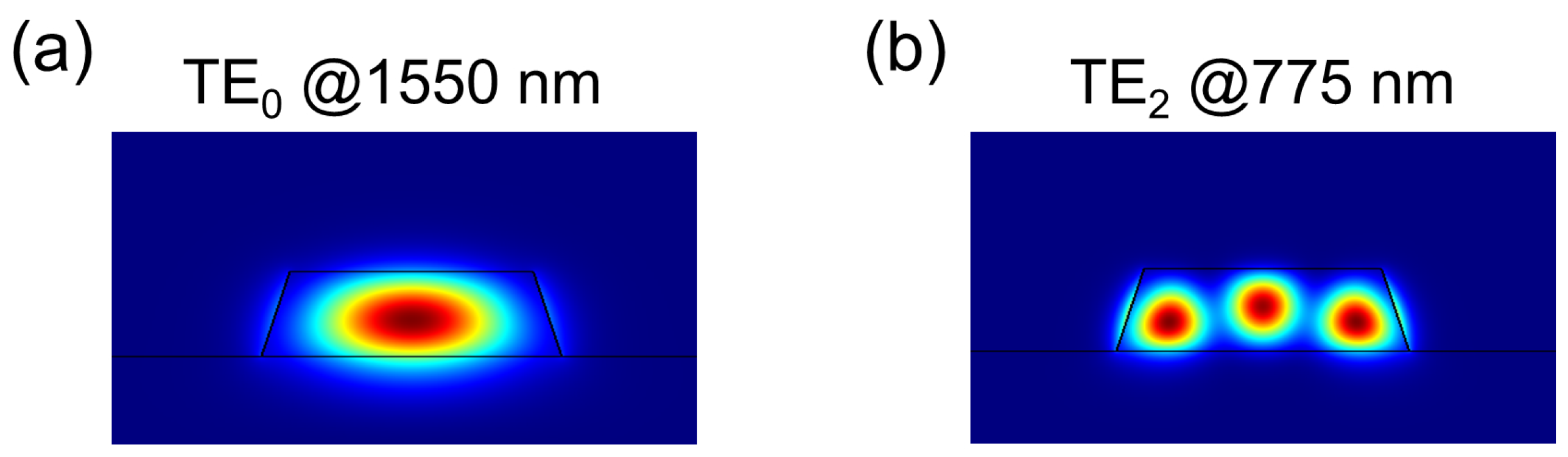
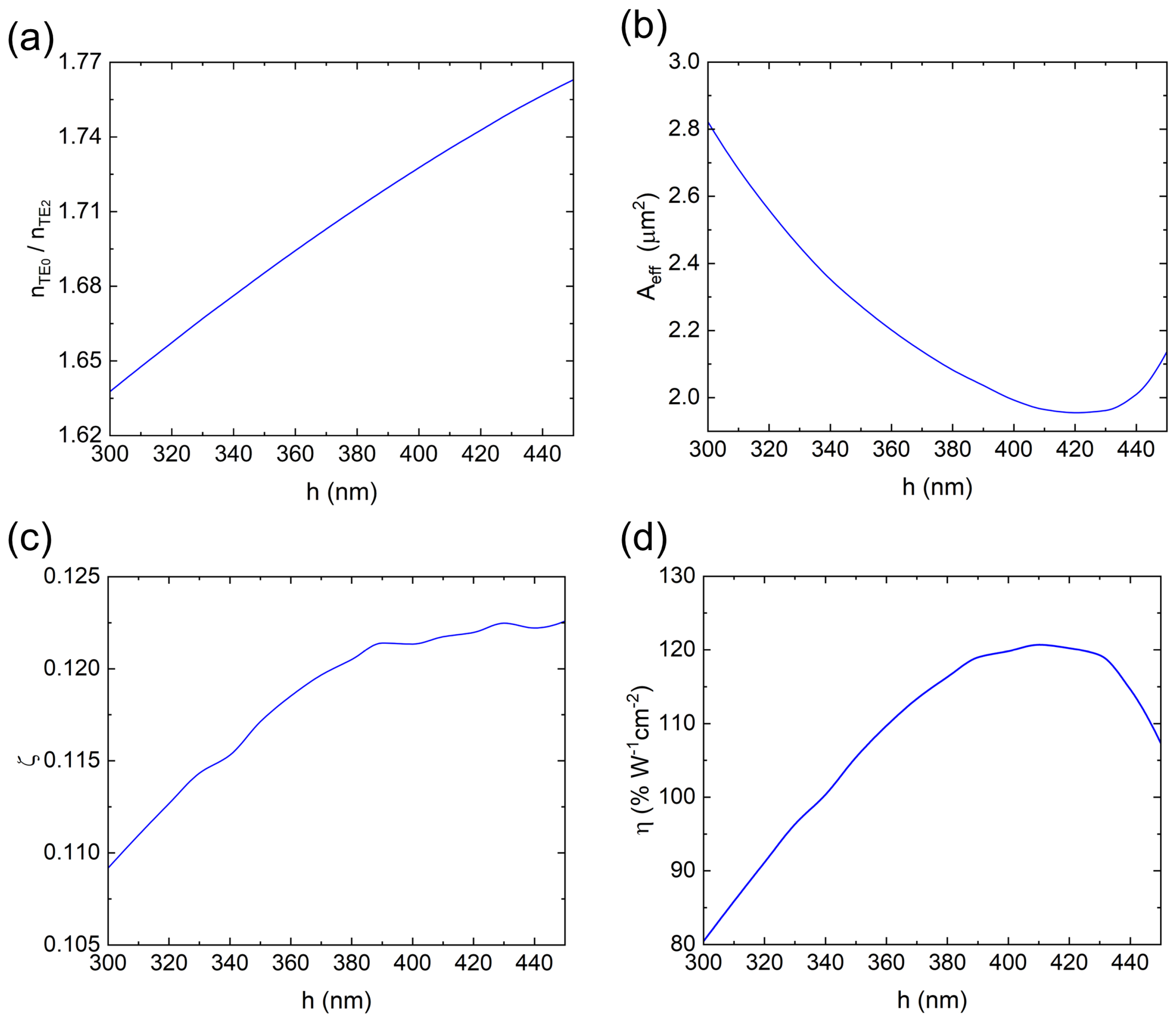
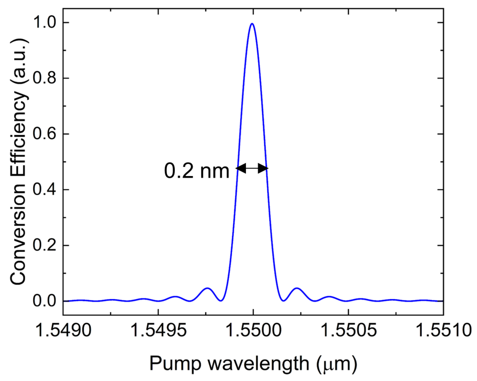
2.1. SHG Based on MPM in TFLN

The objective of SHG is the conversion of light at 1550 nm in the TE0 mode to light at 775 nm in the TE2 mode. The fulfilment of phase-matching conditions is a prerequisite for this process. These conditions can be expressed as the coherent addition of the wave vectors of the interacting waves, which ensures that the momentum is conserved across the nonlinear optical process. This requirement is of paramount importance for the efficient achievement of SHG and can be expressed as follows:
Δ = k T E 2 , s h k T E 0 , f = 0
where k T E 2 , s h = 2 π n T E 2 / λ s h and k T E 0 , f = 2 π n T E 0 / λ f are the wave vectors in the propagation direction for wavelengths of 775 nm and 1550 nm, respectively. λ f and λ s h denote the wavelengths corresponding to the fundamental wave and the second harmonic, respectively. n T E 0 and n T E 2 are the effective refractive indices corresponding to the fundamental wave and the second harmonic, respectively. The section of the device responsible for second-harmonic generation is depicted in Figure 1b, where w represents the top width of the waveguide, h denotes the thickness of the LT. According to the current device parameters [11], the waveguide angle is set at θ = 70°. L S H G is the waveguide length of the SHG process and is set as 10 mm. Above the device is silicon dioxide, and the substrate is silicon dioxide. Figure 2 illustrates the modal field distribution of the two modes.
In the case of a non-absorbing waveguide without pump depletion, the SHG efficiency is given by the following expression, as presented in reference [17]:
Γ = P 2 P 1 2 = η L S H G 2 s i n ( Δ L S H G / 2 ) Δ L S H G / 2 2
where P 1 and P 2 are the optical powers input at the fundamental wavelength and produced at the second harmonic, respectively. When the phase-matching condition ( Δ = 0) is satisfied, Equation (2) indicates the maximum SHG efficiency, denoted as Γ 0 = η L 2 , which depends on the normalised conversion efficiency, that is,
η = 8 π 2 ϵ 0 c n T E 0 2 n T E 2 λ f 2 ζ 2 d e f f 2 A e f f
where ϵ 0 and c are the permittivity and light speed in vacuum, respectively, and d e f f is the effective nonlinear susceptibility. In Equation (3), A e f f = ( A T E 0 2 A T E 2 ) 1 / 3 is the effective mode area. A T E 0 and A T E 2 are given by the following expression:
A i = a l l | E i | 2 d x d z 3 χ ( 2 ) | E i | 2 E i d x d z 2 , ( i = T E 0 , T E 2 )
The parameter ζ represents the spatial mode overlap factor between the fundamental frequency and the second harmonic modes, which is given by
ζ = χ ( 2 ) E T E 0 , z * 2 E T E 2 , z d x d z χ ( 2 ) E T E 0 2 E T E 0 d x d z 2 / 3 χ ( 2 ) E T E 2 2 E T E 2 d x d z 1 / 3
In Equations (4) and (5), a l l and χ ( 2 ) represent the two-dimensional integrals over the entire spatial region and the LT material, respectively. E T E 0 , z is the z-component of E T E 0 ( x , z ) for the fundamental frequency mode TE0. E T E 2 , z is the z-component of E T E 2 ( x , z ) for the second harmonic mode TE2.
As indicated by Equation (1), the attainment of phase-matching conditions is contingent upon the equality of the effective refractive indices of the two modes in question. The objective of the simulations was to investigate the effective refractive indices of two distinct modes across a range of thicknesses. As illustrated in Figure 3, the widths of the waveguides that satisfy the phase-matching conditions for different thicknesses are presented. It is evident that the dimensions of the waveguide that satisfy the phase-matching criteria can be identified when the thickness of the device is varied between 300 and 450 nm.
A meticulous examination of the derivations from Equation (2) to Equation (5) reveals that under phase-matching conditions, the critical parameters influencing the efficiency of SHG are the effective refractive index, the effective mode area, and the spatial mode overlap factor. Figure 4a–c demonstrate the variation in these three parameters under phase-matching conditions for different waveguide dimensions. Figure 4a illustrates that the effective refractive index increases gradually with film thickness, exhibiting a linear trend. Figure 4b illustrates that the effective mode area initially decreases with increasing film thickness, reaching a minimum value at a film thickness of 420 nm, after which it begins to increase again. Figure 4c illustrates that the spatial mode overlap factor gradually increases with thickness.
Figure 4d depicts the trend of the normalised conversion efficiency across a range of varying waveguide dimensions. The initial increase in the normalised conversion efficiency is followed by a gradual decrease with the increase in waveguide thickness. This result is influenced by the effective refractive index, effective mode area, and spatial mode overlap factor of the waveguide. It is observed that the maximum value of the normalised conversion efficiency, expressed in units of 120% W−1cm−2, is attained when the thickness of the film is 410 nm (corresponding to a waveguide top width of 810 nm).
Figure 5 depicts the normalised efficiency spectrum of SHG under the scanning pump wavelength when the film thickness is 410 nm (corresponding to a waveguide top width of 810 nm). This was calculated using Equation (2). In this configuration, the phase-matched pump wavelength exhibiting the highest conversion efficiency is 1550.0 nm, with a 3 dB half-maximum width of 0.2 nm.
Our analysis indicates that within the X-cut TFLT waveguides, efficient SHG can be achieved through MPM. By comparing the normalised conversion efficiency across various dimensions, we have identified the optimal size for maximum conversion efficiency. This method requires no polarisation and is simple to fabricate.

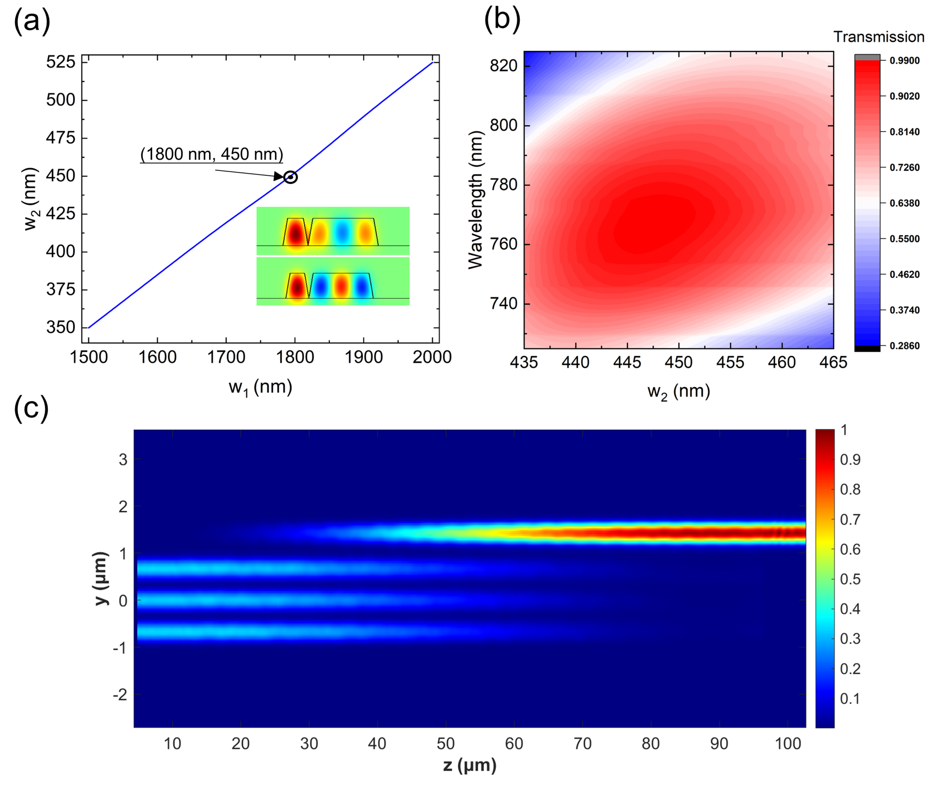
2.2. TE2–TE0 Mode Converter

When high-order modes are coupled to off-chip single-mode fibres or lensed fibres, significant coupling losses may be observed. In order to address the characteristic of the second harmonic mode being in a high-order mode, a mode converter has been designed based on an asymmetric directional coupler with the purpose of converting the TE2 mode to the TE0 mode. Figure 1a,c illustrate a schematic of the mode converter, which comprises two asymmetric waveguides. The waveguide on the left in Figure 1c is connected to the SHG waveguide, transmitting the TE2 mode, with a top width of w 1 . The waveguide on the right side facilitates the coupling of the TE0 mode, which has been converted by the mode converter, off the chip, with a top width of w 2 .
The TE2–TE0 mode converter operates on the principle of leveraging the variation in effective refractive index across waveguides of differing widths. Generally, a wider waveguide boasts a higher effective refractive index for its respective mode. By engineering two waveguides with distinct widths, we can align the effective refractive indices of the TE2 mode in the broader waveguide with that of the TE0 mode in the narrower one. Figure 6a provides a visual representation of the necessary value of w2 for facilitating the transition from TE2 to TE0 mode as the w1 of the SHG waveguide undergoes modification. Notably, there is a direct correlation between the reduction in w1 and the corresponding decrease in w2. In light of the current state-of-the-art in micro–nanofabrication, we have opted for w1 to be 1800 nm, with the corresponding w2 set at 450 nm, dimensions that are well within the scope of our manufacturing capabilities. Once the dimensions of the waveguide have been selected, it is necessary to determine the distance between the two waveguides in the mode converter. The coupling gap at the base of the waveguides is set to zero, as illustrated in Figure 1c. A further crucial parameter of the mode converter is the length. In accordance with the effective refractive indices of the symmetric and antisymmetric modes generated by the coupling of the two modes in supermode theory, the length for complete energy conversion is given by [18]
L M C = λ s h 2 ( n s n a s )
where n s and n a s denote the effective refractive indices of the symmetric and antisymmetric modes, respectively. The values of n s and n a s are determined by MODE Solutions and the mode field distributions for symmetric and antisymmetric modes in coupled waveguides are shown in the inset of Figure 6a. Therefore, L M C is calculated as 86 μm from Equation (6).
In our quest to refine the performance of the mode converter for optimised energy transfer, we conducted 3D-FDTD simulations. These simulations were pivotal in evaluating the transmission performance across a spectrum of wavelengths, specifically for varying widths of w 2 from 435 nm to 465 nm. The results, as depicted in Figure 6b, are quite remarkable, showcasing that our mode converter is capable of achieving nearly perfect efficiency, with a mode conversion efficiency of nearly 100% (insertion loss of less than 0.1 dB) at a specific wavelength. This level of efficiency is not only impressive but also indicative of the device’s potential for high-fidelity energy transfer. Furthermore, the simulations revealed that our device possesses a 3 dB bandwidth for wavelength transmission that extends over 90 nm, a testament to its broad operational range. A particularly noteworthy aspect is the sustained efficiency of over 60% in mode conversion at an SHG pump wavelength of 775 nm, even with variations in w 2 of approximately 30 nm. This robustness against variations in design parameters underscores the adaptability of our approach.
Figure 6c provides a visual representation of the energy transmission process through the mode converter, vividly illustrating the efficient transition from the TE2 mode to the TE0 mode. The clarity and effectiveness of this conversion are evident, further highlighting the device’s promise for achieving high-efficiency energy transfer within the realm of integrated photonic circuits.

3. Discussion

Following simulation validation, the SHG scheme based on TFLT has demonstrated superior performance. The SHG scheme employing the QPM technique circumvents the intricate step of periodic poling, achieving a normalised efficiency of up to 120% W−1cm−2. With a device length of 10 mm, the overall conversion efficiency can reach 120% W−1. Table 1 presents a comparison of the conversion efficiencies achieved by different SHG schemes in lithium tantalate, indicating that the integrated optical waveguide scheme outperforms both bulk crystal and microdisk configurations in terms of conversion efficiency. This enhanced performance is attributed to the reduced mode confinement provided by the waveguide, which facilitates a higher conversion efficiency.
The SHG through MPM resides in higher-order modes, which may introduce additional complexities for subsequent applications of the second harmonic. To address this issue, the design of a mode converter offers an effective solution. This mode converter is capable of achieving nearly 100% mode conversion efficiency at a wavelength of 755 nm, with the process being virtually lossless for the second harmonic. Furthermore, this scheme can also be employed to realize spontaneous parametric down-conversion [18] in TFLT, effectively overcoming the challenge of exciting high-order mode pump light.

4. Conclusion

In this study, we have successfully demonstrated the highly efficient SHG in TFLT through the innovative application of MPM. Our device leverages the intrinsic modal dispersion of the waveguide to achieve phase-matching, effectively bypassing the complexities associated with traditional poling techniques. Through meticulous design and simulation, we have identified the optimal waveguide dimensions that yield an impressive normalised conversion efficiency of 120% W−1cm−2 at a film thickness of 410 nm, underscoring the potential of TFLT in integrated photonic applications. The mode converter, a critical component of this research, has been designed to address the challenges of high coupling losses typically encountered with higher-order modes. With an insertion loss of less than 0.1 dB, our converter ensures the efficient transformation of the TE2 mode to the TE0 mode. This advancement enables seamless integration with existing on-chip and off-chip optical systems, thereby enhancing the versatility and applicability of our device in real-world scenarios. Our findings not only highlight the potential of TFLT for high-performance SHG but also contribute to the development of integrated nonlinear TFLT platforms.

Author Contributions

Conceptualisation, J.L.; methodology, J.L. and G.X.; investigation, software, J.L. and P.Z.; writing—originaldraft preparation, J.L.; writing—review and editing, J.L. and K.Z.; supervision, Z.Z.; project administration, J.L.; funding acquisition, P.X. All authors have read and agreed to the publishedversion of the manuscript.

Funding

National Key R&D Program of China (2022YFF0712800, 2019YFA0308700).

Institutional Review Board Statement

Not applicable.

Informed Consent Statement

Not applicable.

Data Availability Statement

Data are contained within the article.

Conflicts of Interest

The authors declare no conflicts of interest.

References

  1. Jundt, D.H. Temperature-dependent Sellmeier equation for the index of refraction. Opt. Lett. 1997, 22, 1553. [Google Scholar] [CrossRef] [PubMed]
  2. Poberaj, G.; Hu, H.; Soher, W.; Günter, P. Lithium niobate on insulator (LNOI) for micro-photonic devices. Laser Photon. Rev. 2012, 6, 488. [Google Scholar] [CrossRef]
  3. Meyn, J.P.; Fejer, M. Tunable ultraviolet radiation by second-harmonic generation in periodically poled lithium tantalate. Opt. Lett. 1997, 22, 1214. [Google Scholar] [CrossRef] [PubMed]
  4. Eknoyan, O.; Yoon, D.; Taylor, H. Low-loss optical waveguides in lithium tantalate by vapor diffusion. Appl. Phys. Lett. 1987, 51, 384. [Google Scholar] [CrossRef]
  5. Targat, R.L.; Zondy, J.J.; Lemonde, P. 75%-efficiency blue generation from an intracavity PPKTP frequency doubler. Opt. Commun. 2005, 247, 471. [Google Scholar] [CrossRef]
  6. Zhu, D.; Shao, L.; Yu, M. Integrated photonics on thin-film lithium niobate. Adv. Opt. Photonics 2021, 13, 242. [Google Scholar] [CrossRef]
  7. Boes, A.; Chang, L.; Langrock, C. Lithium niobate photonics: Unlocking the electromagnetic spectrum. Science 2023, 379, eabj4396. [Google Scholar] [CrossRef]
  8. Xiao, X.; Liang, S.; Si, J. Performance of LiTaO3 Crystals and Thin Films and Their Application. Crystals 2023, 13, 1233. [Google Scholar] [CrossRef]
  9. Bruner, A.; Eger, D.; Oron, M.B. Temperature-dependent Sellmeier equation for the refractive index of stoichiometric lithium tantalate. Opt. Lett. 2003, 28, 194. [Google Scholar] [CrossRef]
  10. Yu, J.; Ruan, Z.; Xue, Y. Tunable and stable micro-ring resonator based on thin-film lithium tantalate. APL Photon. 2024, 9, 036115. [Google Scholar] [CrossRef]
  11. Wang, C.; Li, Z.; Riemensberger, J. Lithium tantalate photonic integrated circuits for volume manufacturing. Nature 2024, 629, 784. [Google Scholar] [CrossRef] [PubMed]
  12. Cundiff, S.T.; Ye, J. Colloquium: Femtosecond optical frequency combs. Rev. Mod. Phys. 2003, 75, 325. [Google Scholar] [CrossRef]
  13. Newman, Z.L.; Maurice, V.; Drake, T. Architecture for the photonic integration of an optical atomic clock. Optica 2019, 6, 680. [Google Scholar] [CrossRef]
  14. Shen, Y.R. Surface properties probed by second-harmonic and sum-frequency generation. Nature 1989, 337, 519. [Google Scholar] [CrossRef]
  15. Guo, X.; Zou, C.L.; Schuck, C. Parametric down-conversion photon-pair source on a nanophotonic chip. Light. Sci. Appl. 2017, 6, e16249. [Google Scholar] [CrossRef] [PubMed]
  16. Rao, A.; Abdelsalam, K.; Sjaardema, T. Actively-monitored periodic-poling in thin-film lithium niobate photonic waveguides with ultrahigh nonlinear conversion efficiency of 4600%W−1cm−2. Opt. Express 2019, 27, 18. [Google Scholar] [CrossRef]
  17. Luo, R.; He, Y.; Liang, H. Highly tunable efficient second-harmonic generation in a lithium niobate nanophotonic waveguide. Optica 2018, 5, 8. [Google Scholar] [CrossRef]
  18. Liu, J.; Duan, J.; Zhu, P.; Xia, G.; Hong, Q.; Zhang, K.; Zhu, Z.; Qin, S.; Xu, P. Modal phase-matching in thin-film lithium niobate waveguides for efficient generation of entangled photon pairs. Opt. Express 2024, 32, 23. [Google Scholar] [CrossRef]
  19. Tovstonog, S.V.; Kurimura, S.; Suzuki, I.; Takeno, K.; Moriwaki, S.; Ohmae, N.; Mio, N.; Katagai, T. Thermal effects in high-power CW second harmonic generation in Mg-doped stoichiometric lithium tantalate. Opt. Express 2008, 16, 15. [Google Scholar] [CrossRef]
  20. Yan, X.; Liu, Y.; Ge, L.; Zhu, B.; Wu, J.; Chen, Y.; Chen, X. High optical damage threshold on-chip lithium tantalate microdisk resonator. Opt. Lett. 2020, 45, 4100. [Google Scholar] [CrossRef]
  21. Yan, X.; Xue, M.; Yuan, T.; Wu, J.; Ge, R.; Chen, Y.; Chen, X. Cascaded degenerate four-wave mixing generation in thin-film lithium tantalate microdisk cavity. Phys. Rev. Appl. 2024, 21, 024033. [Google Scholar] [CrossRef]
Figure 1. (a) Overall structure of the device. (b) Schematic cross-section of the SHG section. (c) Schematic cross-section of the mode converter section.
Photonics 11 01150 g001
Figure 2. (a) Mode field distribution of TE0 at 1550 nm. (b) Mode field distribution of TE2 at 775 nm.
Photonics 11 01150 g002
Figure 3. w and h corresponding to TFLN waveguides satisfying the phase-matching condition.
Photonics 11 01150 g003
Figure 4. (a) Effective refractive index at different waveguide sizes. (b) Effective mode area at different waveguide sizes. (c) Spatial mode overlap factor at different sizes. (d) Normalised conversion efficiency at different sizes.
Photonics 11 01150 g004
Figure 5. Conversion efficiency (a.u.) at different pump wavelengths.
Photonics 11 01150 g005
Figure 6. (a) Values of w2 for facilitating the transition from TE2 to TE0 mode as the w1 of the SHG waveguide undergoes modification. Inset: Mode field distributions for symmetric and antisymmetric modes in coupled waveguides. (b) The transmission properties of the mode converter at different wavelengths for different w2. (c) Results of the optical field transmission distribution obtained from FDTD simulations.
Photonics 11 01150 g006
Table 1. Comparison of conversion efficiency of SHG in lithium tantalate.
ReferenceStructureConversion Efficiency
Sergey et al. [19]Crystal0.66 %   W 1
Yan et al. [20]Microdisk0.0008 %   W 1
Yan et al. [21]Microdisk13.3 %   W 1
This workWaveguide120 %   W 1
Disclaimer/Publisher’s Note: The statements, opinions and data contained in all publications are solely those of the individual author(s) and contributor(s) and not of MDPI and/or the editor(s). MDPI and/or the editor(s) disclaim responsibility for any injury to people or property resulting from any ideas, methods, instructions or products referred to in the content.

