Abstract
A freeform off-axis three-mirror anastigmat (TMA) optical system with a large field of view (FOV) can obtain target image information with a larger spatial range and more spatial details, which is a development trend within the realm of space optics. The optical aberration increases exponentially with the FOV, resulting in a significant increase in error sensitivity for large-FOV optical systems. To address this issue, a method for designing optical systems with a large FOV and low error sensitivity is proposed. The FOV is gradually expanded from a small initial value in equal-length increments until it reaches the full FOV. At each step, the error sensitivity is recalculated and controlled to a lesser extent than in the previous step. In this design process, the freeform surface is used to correct the aberration and obtain low error sensitivity. An optical system with a focal length of 1000 mm and an F-number of 10 is used as an example, and the FOV is enlarged from 5° × 1° to 20° × 4°. The design results show that the modulation transfer function (MTF) of the optical system can reach 0.45@50 lp/mm, and the average wavefront aberration is 0.029λ. After four rounds of FOV expansion and error sensitivity optimization, the error sensitivity is reduced by 37.27% compared to the initial system, which verifies the correctness and practicality of the method.
1. Introduction
TMA optical systems can simultaneously correct spherical aberration, coma, and astigmatism, and can achieve performance advantages such as a large relative aperture, achromaticity, good spot diagram energy concentration, and no central obstruction [1,2,3,4,5]. It has been successfully applied in optical systems of remote sensing cameras represented by QuickBird, CARTOSAT-1, HiRIC, etc. [6,7,8]. In the field of space optics, to obtain target image information with a larger spatial range and more spatial details, optical systems are continuously evolving towards a large FOV while pursuing high resolution. A large FOV means that the optical system can acquire a wider spectral range and a larger observation range, resulting in a shorter revisit cycle and an improved temporal resolution for the overall instrument. In the process of designing large FOV off-axis TMA optical systems, it is difficult to achieve a large FOV with a simple surface type due to limited design degrees of freedom (DOFs), and the imaging width is restricted. Freeform surfaces, benefiting from their rich DOFs, is a hot topic within the realms of both imaging [9] and non-imaging optics [10,11]. Freeform surfaces can be applied in off-axis TMA optical systems to balance aberrations, expand the FOV, and improve image quality, bringing great convenience to the production of high-performance optical systems with large FOVs [12,13,14,15].
The traditional design method for large-FOV off-axis TMA optical systems typically involves initially obtaining a coaxial optical system, moving the coaxial system off-axis, and subsequently optimizing it to achieve the final optical system. Due to the significant deviation between the initial coaxial optical system and the final structure of the large-FOV off-axis system, the optimization design process is very complex. In 2018, Tang et al. designed a freeform off-axis TMA optical system with a large linear FOV of 60° × 1° [16], and Hou et al. designed a freeform off-axis TMA optical system with a large linear FOV of 70° × 1° [17]. In 2019, Meng et al. designed a freeform off-axis TMA system with a rectangular FOV of 80° × 4° [18]. The initial structures of the first two designs were developed using the construction-iteration (CI-3D) method, while the initial structure of the latter design was obtained by selecting a large-FOV optical system in the published paper. The common denominator in the design process of these large-FOV freeform off-axis TMA optical systems is adopting the method of expanding the FOV step by step. In the expansion and optimization process, the design results obtained in the adjacent stages are similar, making the optimization process simpler, thus this method is highly effective for designing large-FOV optical systems.
However, in the production process of an optical system, a good design result is just a starting point. The errors generated during the subsequent manufacturing and alignment processes are the key factors that determine whether the optical system can achieve its as-built performance [19]. Error sensitivity can characterize the image quality degradation caused by errors in an optical system. Optical systems with low error sensitivity can obtain a loose tolerance which reduces the production costs, while improving the feasibility of the design result. According to the aberration theory, optical aberrations increase exponentially with the FOV, leading to a significant increase in error sensitivity as the FOV expands. It is of great significance to achieve high-performance off-axis TMA optical systems with large FOVs while simultaneously reducing error sensitivity. This is crucial for the realization of high-performance imaging in large-FOV freeform TMA optical systems.
Currently, the desensitization design methods for optical systems are the global optimization method [20,21,22,23], the multiple structure method [24,25], and the parameter control method [26,27,28,29,30,31,32]. In the design process of optical systems with a large FOV, freeform surfaces are often used for image quality optimization. The wide range of the working FOV results in certain differences in parameters for different working regions [33]. However, there is a lack of clear guidance on desensitization design methods for freeform optical systems with large FOVs in existing research methods.
In light of the above discussion, this paper provides supplementary analysis to the desensitization design methods proposed by the team in the previous stage [28,30], aiming to clarify the common factors between these desensitization methods, and guide the design of freeform off-axis TMA optical systems. A design method of synchronously adjusting the FOV and error sensitivity is proposed. While expanding the FOV, the surface parameters of the newly added working region are controlled. This ensures that the evaluation function values at the intersection points of each incidence ray and the mirror surface decrease, allowing the optical system to achieve both a large FOV and low error sensitivity. Taking an off-axis three-mirror optical system with a focal length of 1000 mm and an F-number of 10 as an example, the FOV is enlarged from 5° × 1° to 20° × 4°, and the error sensitivity is reduced by 37.27% compared with the initial structure. And the average root mean square of the wavefront error (RMS WFE) is 0.029λ (λ = 632.8 nm), the MTF can reach 0.45@50 lp/mm, and the distortion value is less than 0.5%, the image performance of the freeform off-axis TMA optical system performs well.
2. Error Sensitivity Analysis and Merit Function
In this paper, as in our previous research, the wavefront error (WE) is employed as the criterion for evaluating image quality and analyzing error sensitivity. The change in WE can effectively characterize the error sensitivity of the optical system, which can be represented by ∆WE. The complexity of the surface type results in a different WE at the intersection points of different incident rays and the mirror. This leads to varying error sensitivity distributions at different positions within the same FOV and pupil, as well as different working regions on the surface for different FOVs, resulting in varying error sensitivity. Therefore, this paper adopts the concept of “micro-elements” and treats the complex freeform surface as a collection of numerous simple spherical surfaces. By controlling the values of the characteristic parameters related to error sensitivity for each spherical surface, the ∆WE caused by the passage of rays through optically disturbed elements is minimized, thereby reducing error sensitivity. This method is applicable for evaluating any smooth and continuous surface types.
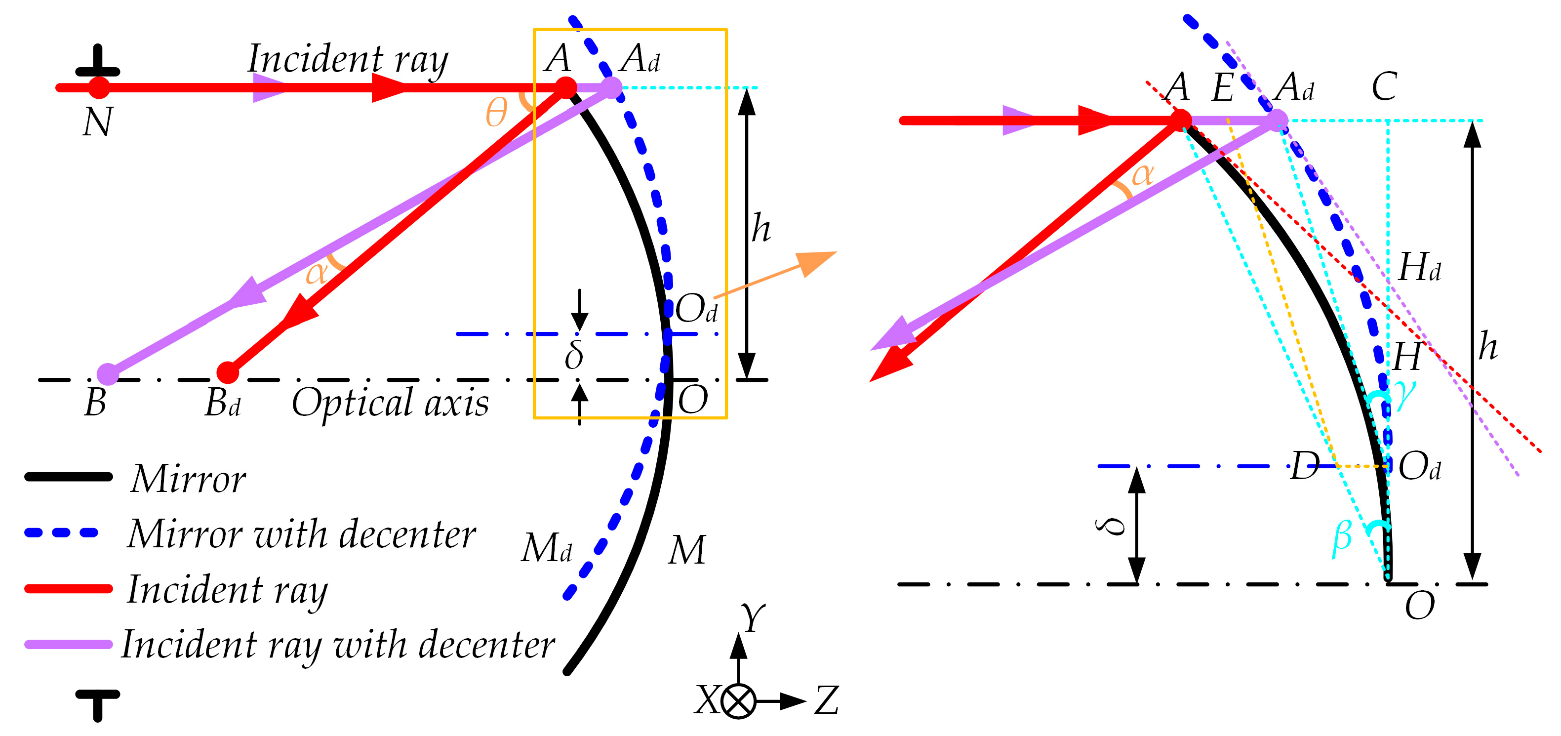
According to the angle optimization desensitization design method targeting tilt errors, it is known that the error sensitivity to tilt is positively correlated with the angle of incidence. The mathematical model of single spherical mirror optical system is constructed in Figure 1 to explore the relationship between the ∆WE and the angle of incidence when the optical system generates decenter errors. The black curve represents the original state of the reflective mirror, and the center of the mirror intersects with the optical axis at point O. The blue dashed curve represents the state of the reflective mirror with decenter. The incident ray intersects with the mirror at point A, and the reflected ray intersects with the optical axis at point B. The decenter error of the mirror is assumed to be δ, the incident ray intersects with the mirror at point Ad, and the reflected ray intersects with the optical axis at point Bd.
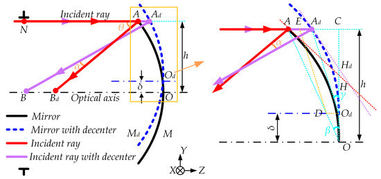
Figure 1.
The mathematical model of single spherical mirror optical system.
Analyzing the reflective mirror with the decenter error, ∆WE can be expressed as
As shown in Figure 1, the mathematical model of a single mirror with decenter error is partially enlarged. Point O is extended to point C by drawing a perpendicular line OC to the extension of line AAd. Line AdOd is then connected, and angle ∠AdOdCd is denoted as γ. Line AO is connected, and angle ∠AOC is denoted as β. A perpendicular line is drawn from point Od to line OC, intersecting line AO at point D. A parallel line is drawn from point D to line AdOd, intersecting line AAd at point E.
Thus, AAd can be expressed as
In the parallelogram EAdOdD, where DOd is parallel to and equal to EAd, according to the triangle relationships shown in Figure 1, we can determine the values of AE and EAd as follows
Thus, the AAd can be rewritten as
For the same mirror and incident ray, once the decenter error δ is determined, the point at which the incident ray and the mirror intersect is also determined. Therefore, the angles γ and β are only related to δ. According to Equation (5), when the basic parameters of the optical system are fixed, AAd is a constant value and is independent of the incident angle.
Next, AdBd-AB is calculated. Assuming that AH be the tangent to point A and intersects OC at point H, AdHd be the tangent to point Ad, intersecting OC at point Hd. The angle between AH and AdHd is denoted as ψ. Since the mirror surface is spherical, the following angle relationships can be derived
Therefore, the angle ψ is 2|β − γ|, so the angle between AB and AdBd, α, is equal to 2|β − γ|. The value of α is determined by the angles γ and β, regardless of the direction of the angle. Therefore, α is always positive and only depends on the decenter error δ. Thus, we can calculate the value of AdBd − AB as
In the equation, θ represents the incident angle, which is the angle between the incident ray and the normal to the mirror. It only represents the value and not the direction, so the range of values for θ is (0, π/2).
Let us assume that AdBd − AB is denoted as Q. Then,
In the production process, as the optical alignment accuracy improves, the decenter error δ should be a very small value and show a decreasing trend, and consequently, α is a small constant value, which can be derived from the Newton-Leibniz formula
The first derivative of Q with respect to θ being greater than zero indicates that Q monotonically increases with θ. The quantity AdBd − AB monotonically increases with the incident angle θ.
From the above analysis, it can be concluded that ΔWE monotonically increases with the incident angle, which is consistent with the conclusion of the tilt error sensitivity analysis. The decenter error sensitivity is also positively correlated with the incident angle. Therefore, whether controlling tilt or decenter error sensitivity, it can be achieved by controlling the incident angle.
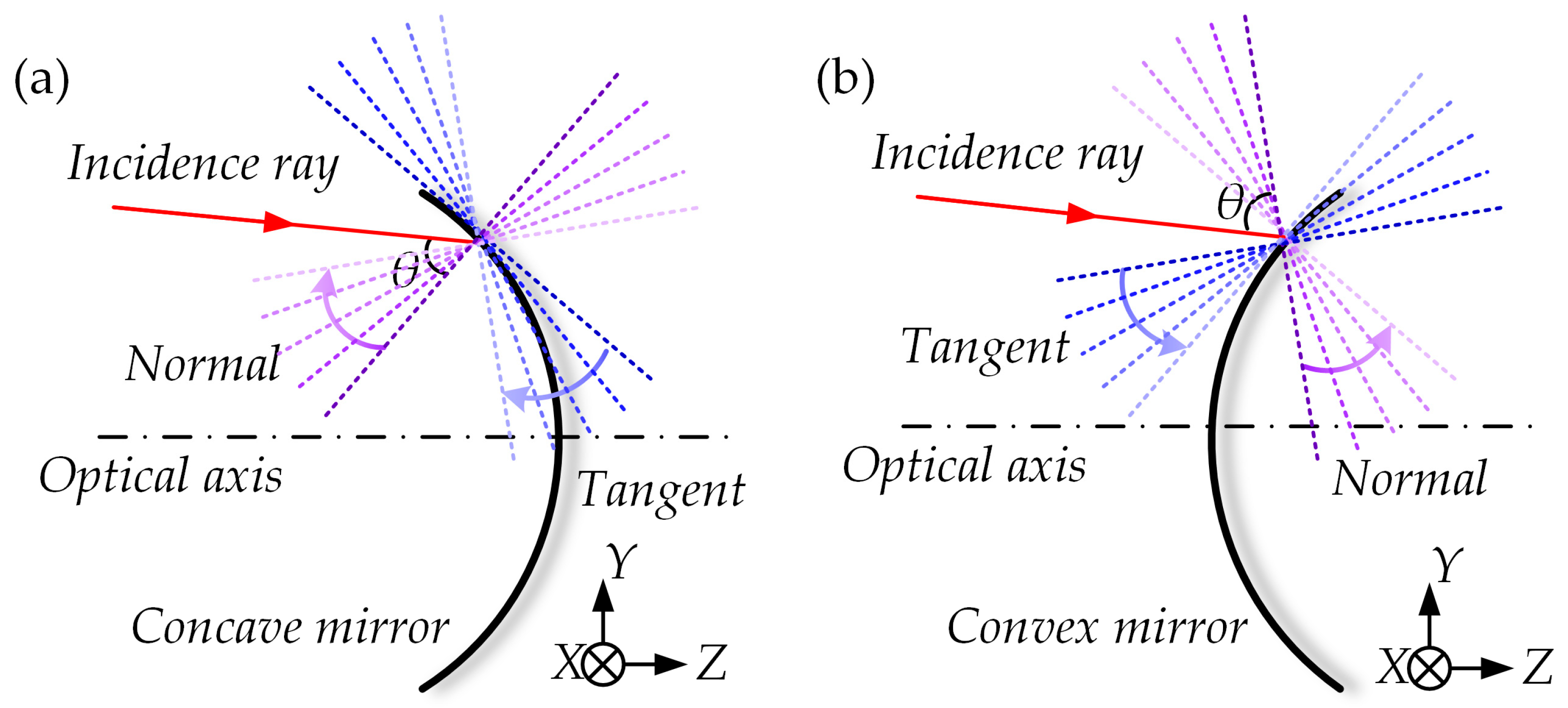
The incident angle can be represented by the normal slope. The schematic diagram of the relationship between the incidence angle and the normal slope of the mirror is shown in Figure 2, and to make it clearer, the variation on the mirror surface is not depicted. For a given incident ray, due to the influence of errors, in Figure 2, the blue lines from dark to light represent the tangent slope variation of the mirror surface at the intersection point of the incident ray and the mirror, and the purple lines from dark to light represent the normal slope variation on the mirror surface at the intersection point of the incident ray and the mirror. If the mirror is concave, as shown in Figure 2a, the normal slope is positive, and the smaller the normal slope, the smaller the incident angle θ. If the mirror is convex, as shown in Figure 2b, the normal slope is negative, and the larger the normal slope, the smaller the incident angle θ. Therefore, the incident angle θ is positively correlated with the absolute value of the normal slope. Thus, by controlling the absolute value of the normal slope at the intersection point of the incident ray and the mirror, the incident angle can be controlled, thereby controlling the error sensitivity.
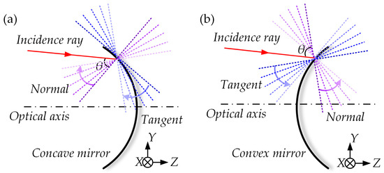
Figure 2.
Schematic diagram of the relationship between the incidence angle and the normal slope of the mirror: (a) concave mirror; (b) convex mirror.
Since the optical surface is spherical, the mirror sag equation can be simplified as follows
where c is the vertex curvature and r is the radial distance of the mirror intersection point from the optical axis.
The absolute value of the normal slope (AS), can be written as
where there is only one variable in the equation, the surface curvature. Taking the derivative of AS with respect to c can be expressed as
Clearly, Equation (11) is greater than zero. AS increases monotonically with the absolute value of c (AC). Therefore, for a local position on the surface, as AC decreases, AS decreases, and the incident angle decreases, resulting in a lower sensitivity to tilt and eccentricity errors in the optical system.
Based on the above analysis, we propose the error sensitivity evaluation function MFf for a single FOV in the optical system
where n is the serial number of mirrors, with a total of NM mirrors; ω is the serial number of rays within each FOV in the optical system, with a total of NR rays.
The comprehensive error sensitivity evaluation function for the optical system is denoted as MF. This evaluation function is applicable for evaluating the tilt and decenter error sensitivity of all smooth and continuous surface shapes. MF can be written as
where f is the serial number of FOVs, with a total of NF FOVs.
3. Design Method for Freeform Off-Axis TMA Optical Systems with a Large FOV and Low Error Sensitivity
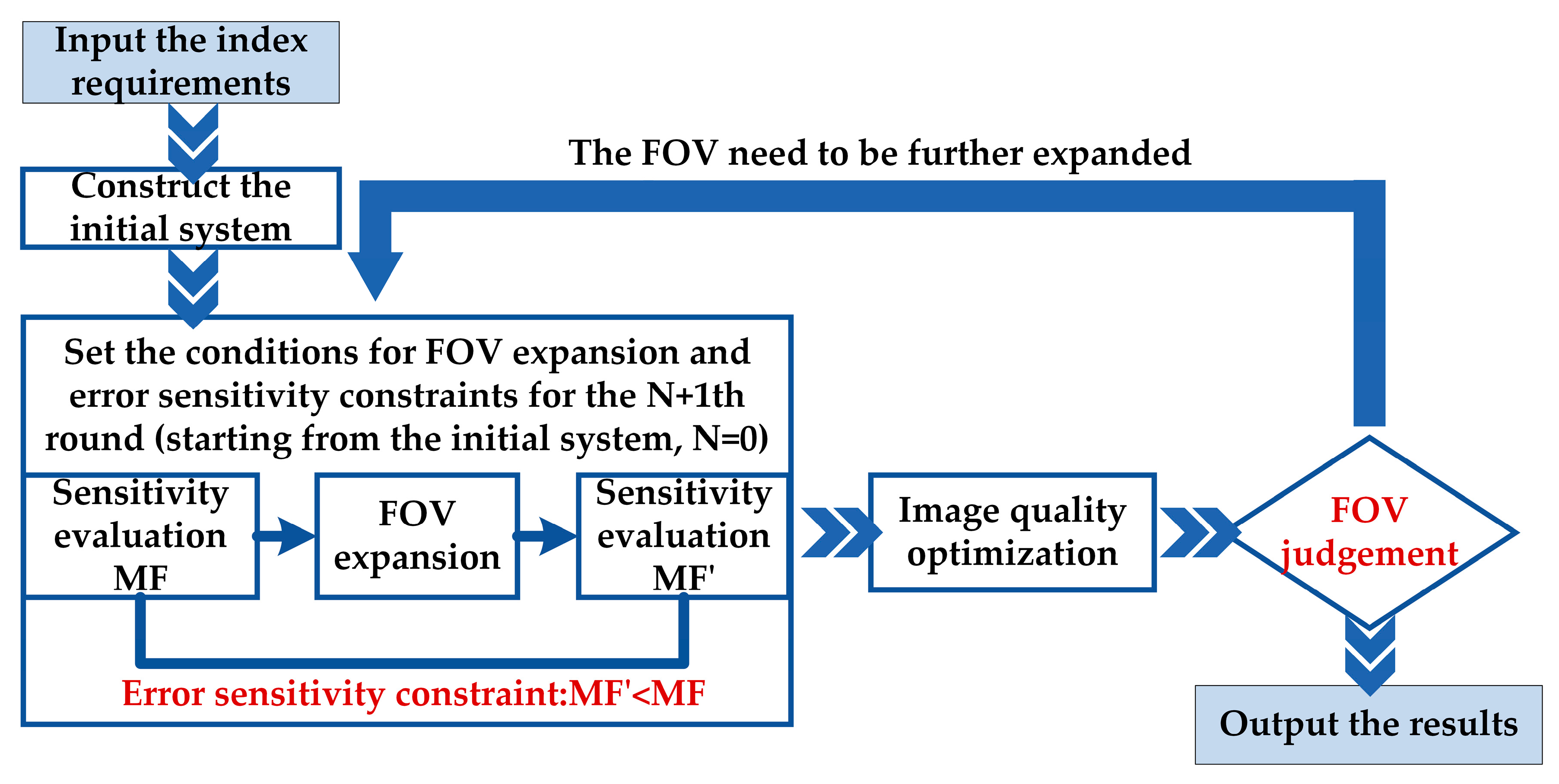
Based on the previous analysis, a design method for freeform off-axis TMA systems with large FOV and low error sensitivity is established, with the error sensitivity evaluation function MF as the core, the schematic diagram of the design process is shown in Figure 3. The main idea of the design method is to gradually control the MF value in the optical system while expanding the FOV. This is achieved through surface type upgrades and optimization design. The design method consists of the following steps:
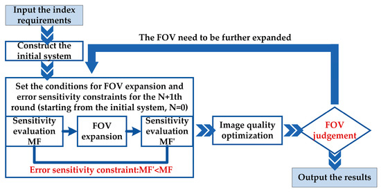
Figure 3.
Schematic diagram of freeform off-axis TMA systems with a large FOV and low error sensitivity design process.
- (1)
- Construct the initial system of the optical system based on the design requirements and set the initial structural constraints.
- (2)
- Set the conditions for FOV expansion and error sensitivity constraints for the N + 1th round (starting from the initial system, N = 0):
- Set the error sensitivity threshold. Calculate the evaluation function value MF based on the existing FOV and set it as the threshold for the sensitivity evaluation. The error sensitivity in the subsequent design process should be lower than MF.
- FOV expansion. Set the step length for expanding the FOV of the optical system based on the requirements. Gradually expand the FOV in the meridional and sagittal directions with a certain step length.
- Set error sensitivity constraints. After the FOV expansion, recalculate the evaluation function value MF′ for all FOVs. Control the MF′ value of the newly added FOV to be lower than the threshold MF. This is the error sensitivity constraint condition.
- (3)
- Image quality optimization. Recalculate the structural constraints and optimize the image quality of the optical system based on the structural constraints and error sensitivity constraints. If the optical system does not meet the image quality requirements, increase the DOFs of the optical system, such as upgrading the surface type to freeform surfaces, until the image quality meets the requirements.
- (4)
- Determine if the FOV meets the requirements. If it does, output the freeform off-axis TMA system with a large FOV and low error sensitivity that meets the image quality requirements. If it does not meet the requirements, return to step (2).
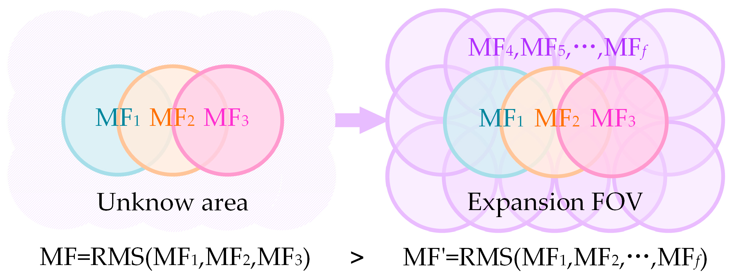
The design method proposed in this paper expands the FOV in both the meridional and sagittal directions. In the design process, the expansion of the FOV is synchronized with the error sensitivity constraint. A schematic diagram of FOV expansion and error sensitivity constraint condition is shown in Figure 4, the initial structure only has three FOVs. By sampling the rays within the FOV and calculating the evaluation function values (MF) for each FOV, an error sensitivity threshold is set. During the first round of FOV expansion, the unknown area will be included as part of the working field, and the evaluation function values (MF′) for all 15 FOVs need to be recalculated. The error sensitivity constraint condition is set as MF′ < MF, and the image quality is optimized until the requirements are met. This process is repeated for subsequent rounds of FOV expansion until a large-FOV off-axis TMA optical system with low error sensitivity that meets the performance requirements is obtained.
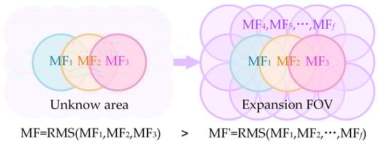
Figure 4.
Schematic diagram of FOV expansion and error sensitivity constraint condition.
4. Design Example
4.1. Construct Initial System
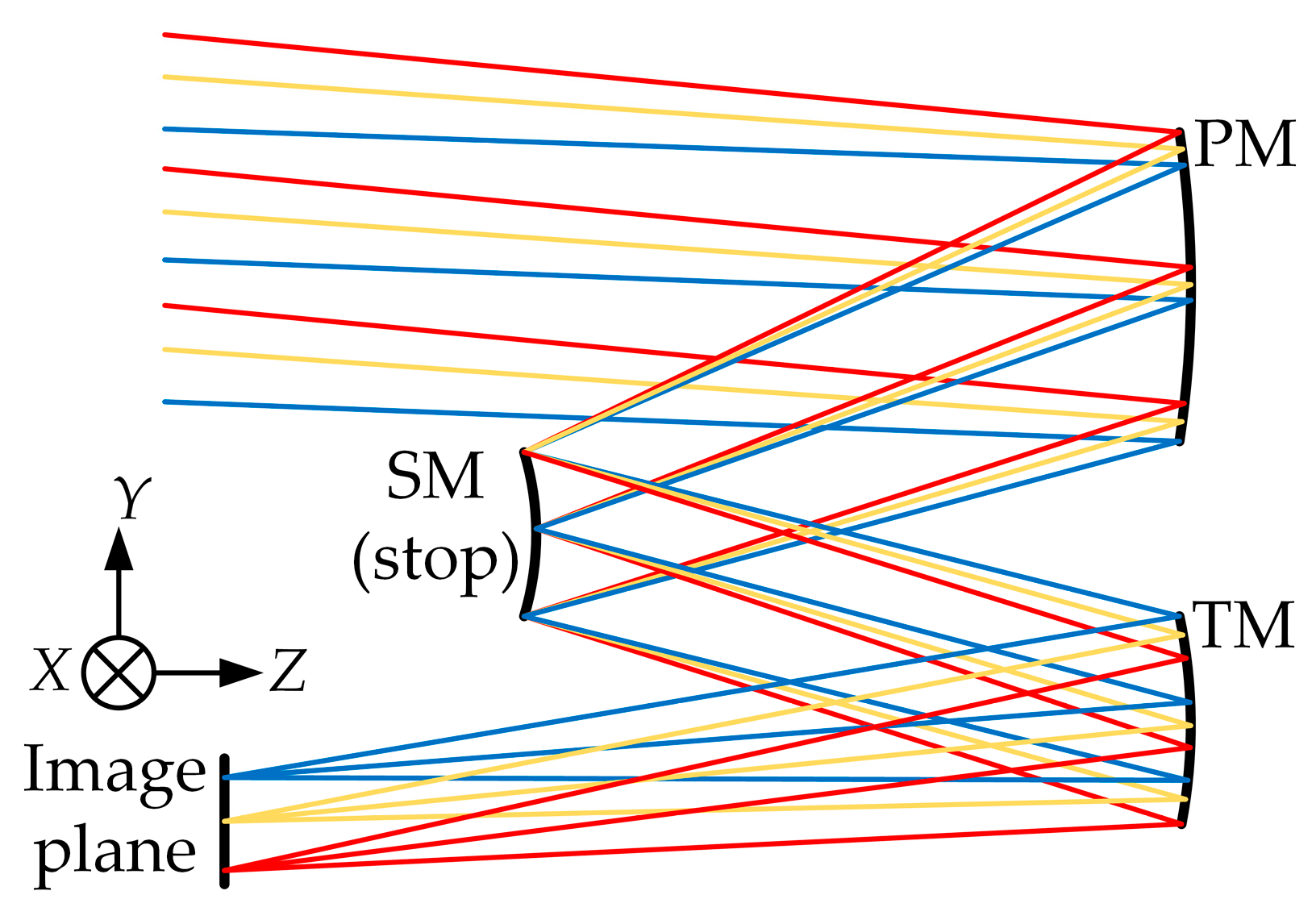
There are dozens of configurations for off-axis TMA optical systems, and the schematic diagram of the off-axis TMA optical system selected in this paper is shown in Figure 5. The stop is placed on the secondary mirror (SM), and the primary mirror (PM) and tertiary mirror (TM) are relatively symmetrical. This configuration is advantageous for achieving a large FOV, with a field angle ranging from 3° to 20°, while maintaining minimal distortion.

Figure 5.
Schematic diagram of off-axis TMA optical system.
RMS WFE is used as the evaluation criterion for both image quality and error sensitivity. Based on the Maréchal criterion, the optical system should achieve an image quality better than 1/14λ. In the off-axis TMA optical system shown in Figure 5, the Random Surface Errors (RSEs) of the PM and TM can reach 1/55λ. With its circular rotationally symmetric structure and compact size, the RSEs of the SM can reach 1/80λ. During the design process, as shown in Equation (15), the RMS WFE of the optical system can be controlled within 0.03λ, while the other allocation margin can be left for alignment [18].
The optical system design parameters, as shown in Table 1, set the obscuration ratios of the SM to the PM and the TM to the SM to α1 = 0.5 and α2 = 1.5, respectively. The magnification ratios of the SM and TM are β1 = 2 and β2 = 0.5, respectively. Based on the third-order aberration theory, an initial coaxial three-mirror optical system is solved. The FOV is set to 5° × 1°, with the meridional direction ranging from −5.5° to −4.5° and the sagittal direction ranging from −2.5° to 2.5°. Through image quality optimization, “System 1” is obtained, with an average RMS WFE of 0.021λ. “System 1” serves as the initial system for subsequent FOV expansion and sensitivity optimization. Both the PM and TM are conic, while the SM is a spherical surface. “System 1” has a total of 9 FOVs, with 18 characteristic rays uniformly sampled within each field (the same ray sampling method is used for each FOV in the subsequent design process as in “System 1”). We believe that increasing the number of sampling rays can enhance the desensitization effect. However, this also results in longer optimization times. Therefore, a compromise can be made by selecting the appropriate number of sampling rays based on specific requirements. The optical system error sensitivity is evaluated using the MF, and “System 1” has an MF value of 0.866.

Table 1.
Optical system index requirements.
In the subsequent design process, the inter-distance, curvature, and conic constant of the optical system are also set as optimization variables to increase the DOFs. The total length of the optical system is controlled to be smaller than the focal length. Additionally, structure constraints need to be recalculated and controlled to guarantee non-crossing and non-obscuration for each round of FOV expansion.
4.2. FOV Expansion and Error Sensitivity Optimization
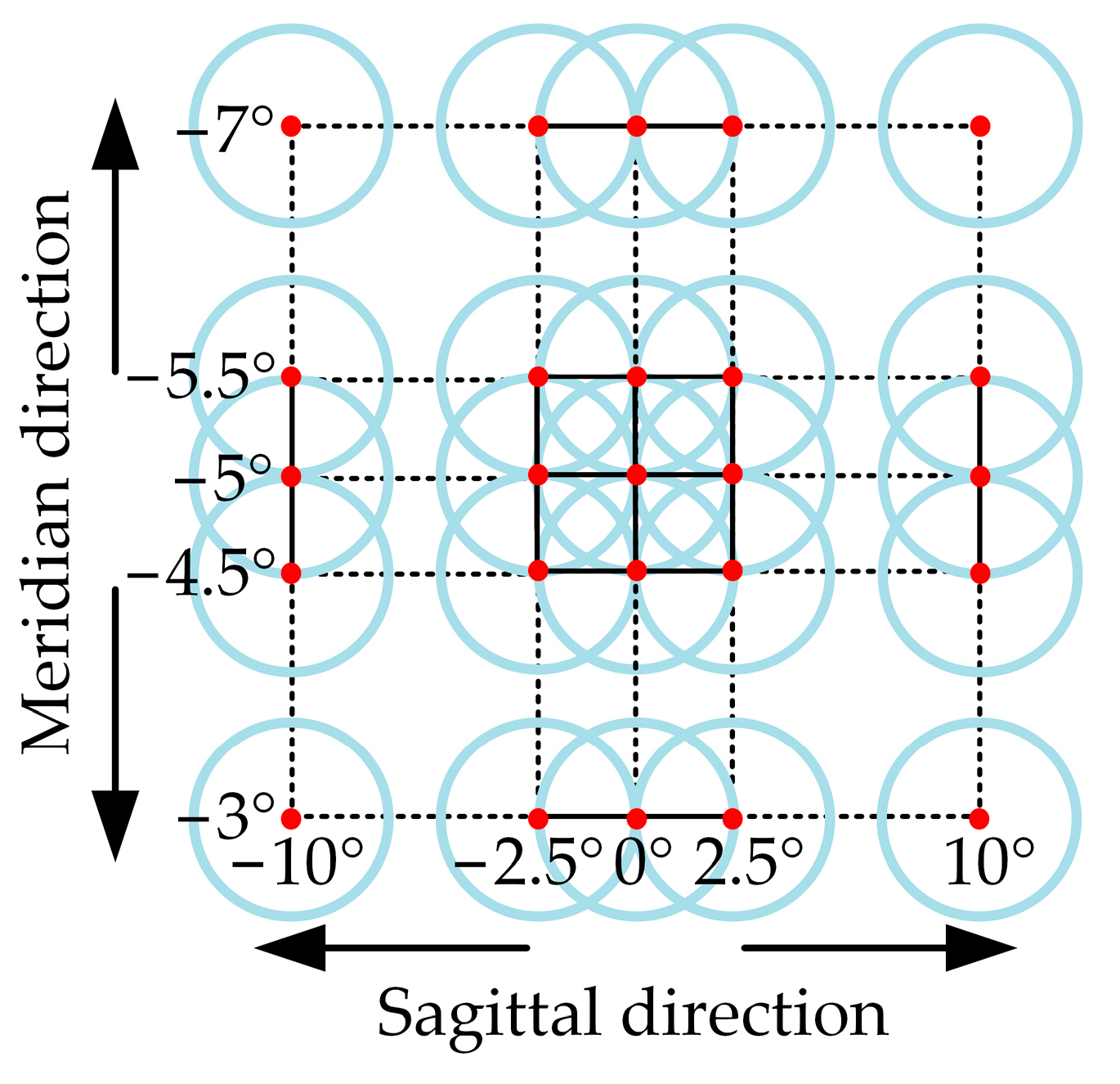
According to “System 1” and the FOV required by the optical system, the FOV is set to expand in the meridional direction with a step length of 0.5° (half of the FOV) and in the sagittal direction with a step length of 2.5° (half of the FOV). And designers can determine the step length based on the design requirements and the optimization time cost. The schematic diagram of the FOV expansion process is shown in Figure 6.
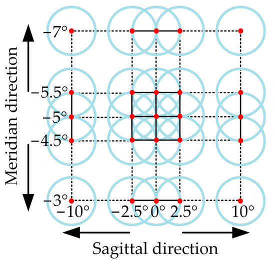
Figure 6.
Schematic diagram of the FOV expansion process.
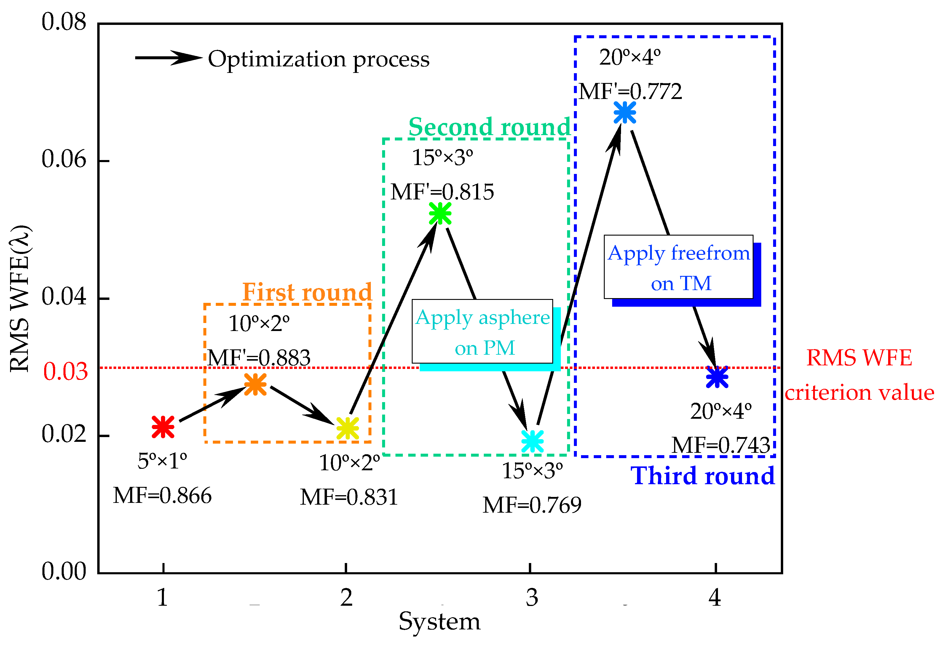
Expanding the FOV from 5° × 1° to 20° × 4° requires three rounds of setting the error sensitivity constraint for FOV expansion. The actual design process is illustrated in Figure 7.
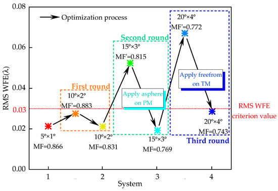
Figure 7.
The actual design process of an off-axis TMA optical system with a large-FOV and low error sensitivity.
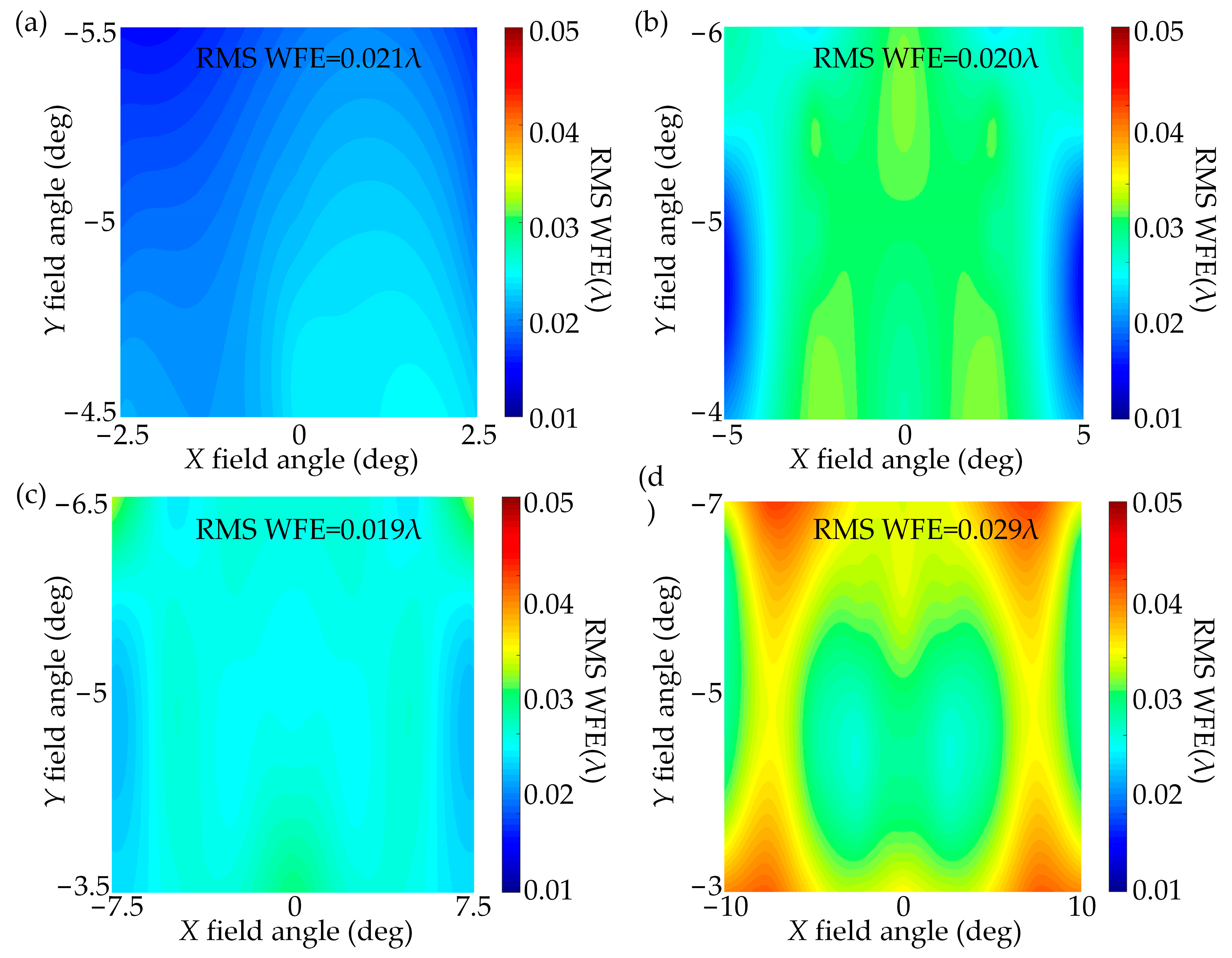
First, we set the error sensitivity constraint for the first round of FOV expansion. The RMS WFE of “System 1” is shown in Figure 8a. The MF of “System 1” is 0.866, which is set as the threshold for the error sensitivity evaluation. The FOV of “System 1” is expanded to 10° × 2°, with a total of 25 sampling FOVs. The RMS WFE of the image quality degrades to 0.028λ while still meeting the image quality requirements. However, the calculated MF’ is 0.883, which exceeds the desired MF threshold. To control MF′ < 0.866, the image quality is optimized, resulting in “System 2” with an MF of 0.831 and an RMS WFE of 0.021λ, as shown in Figure 8b.
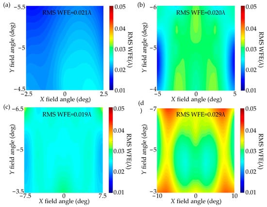
Figure 8.
Field map of RMS WFE. (a) System 1, (b) System 2, (c) System 3, (d) System 4.
Then, we set the error sensitivity constraint for the second round of FOV expansion. At this point, the MF of “System 2” is 0.831. The FOV of “System 2” is further expanded to 15° × 3°, with a total of 49 sampling FOVs. The MF’ after FOV expansion is 0.815, and the RMS WFE is 0.052λ, which meets the sensitivity requirements but not the image quality requirements. To control MF′ < 0.831, further image quality optimization is performed. During the optimization process, an aspherical surface is introduced to the PM, resulting in “System 3” with an MF of 0.769 and an RMS WFE of 0.019λ, as shown in Figure 8c.
Next, we set the error sensitivity constraint for the third round of FOV expansion. At this point, the MF of “System 3″ is 0.769. The FOV of “System 3” is expanded to 20° × 4°, with a total of 81 sampling FOVs. The MF′ is 0.772, and the RMS WFE is 0.067λ. To control MF′ < 0.769, further image quality optimization is performed. During the design process, we should use as few freeform surfaces as possible and a proper number of aspherical surfaces to reduce the cost and manufacturing complexity. Thus, a fifth-order XY polynomial freeform surface is applied on the TM, and only even order terms of x are retained. Then, we obtain the final design, “System 4”, with an MF of 0.743 and an RMS WFE of 0.029λ, as shown in Figure 8d.
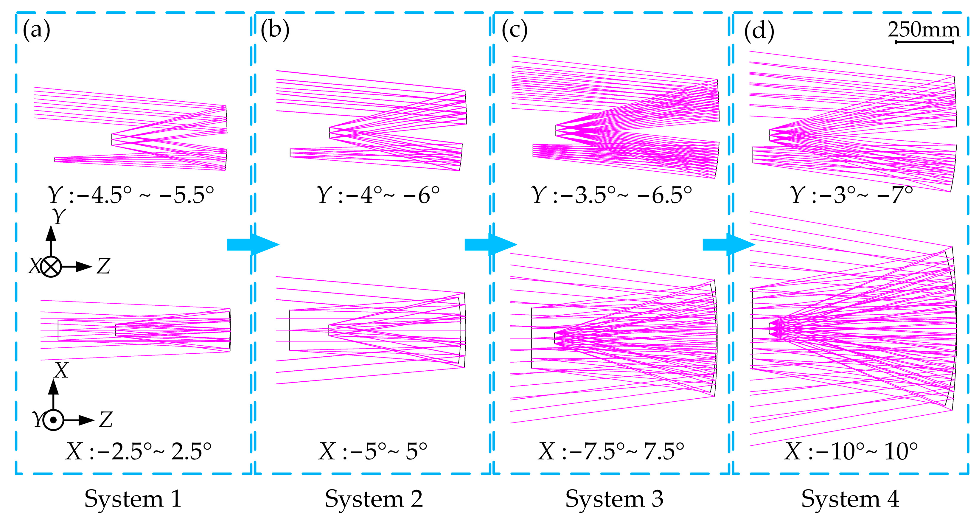
The optimization process for error sensitivity during FOV expansion has yielded four intermediate results, referred to as “System 1” to “System 4”, all of which exhibit good image quality. Throughout the process of expanding the FOV, the image quality in “System 1”, “System 2”, “System 3”, and “System 4” is uniformly distributed. The layout of these systems is shown in Figure 9. The systems have a total length less than the focal length of 1000 mm, satisfying the structural constraints.
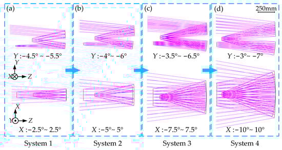
Figure 9.
System layout. (a) System 1, (b) System 2, (c) System 3, (d) System 4.
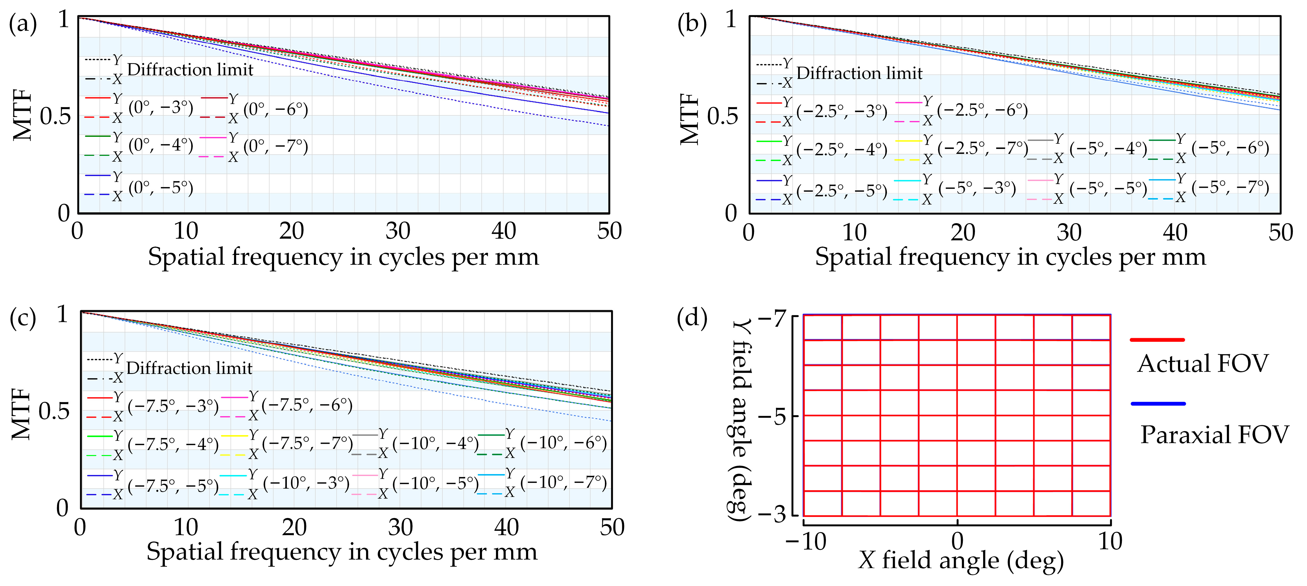
“System 4” is the final design result that meets the requirements of the optical system specifications. The image quality of “System 4” is symmetric about the Y axis, the image quality of half of the FOV can be extended to the full FOV. The MTF of “System 4” is shown in Figure 10a–c, the MTF values for each FOV in the optical system meet the requirements of 0.45@50 lp/mm. The grid distortion of “System 4” is shown in Figure 10d, with a maximum distortion of 0.5%. The distortion is controlled within a very small range.
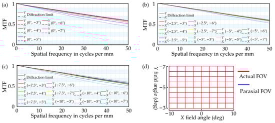
Figure 10.
(a–c) MTF of “System 4”; (d) grid distortion of “System 4”.
4.3. Error Sensitivity Analysis
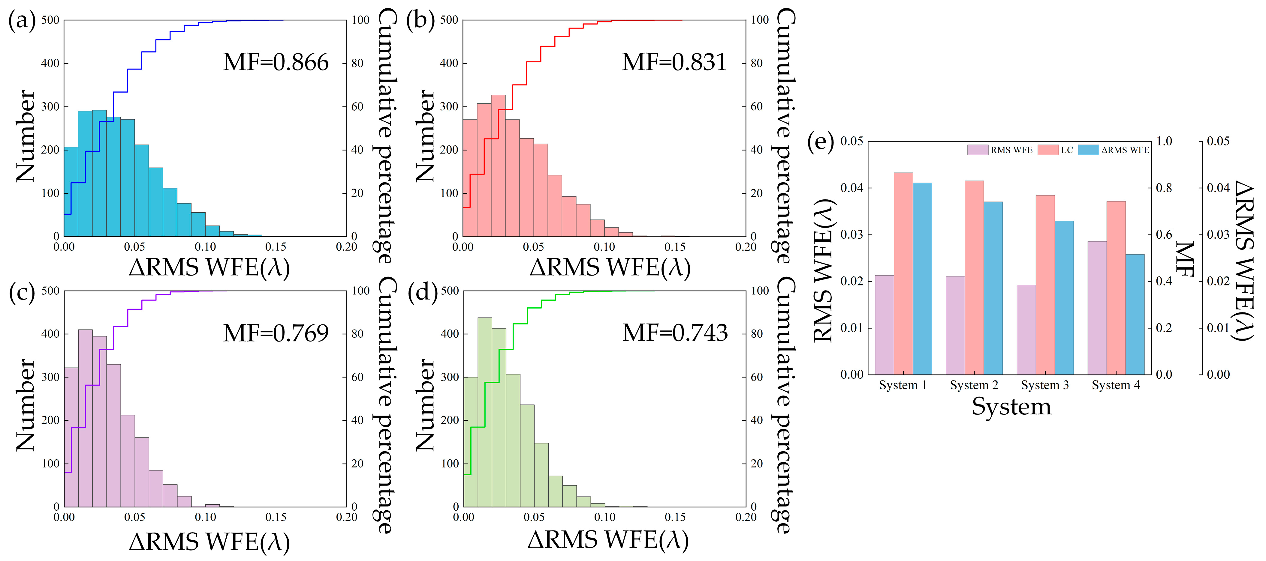
The four intermediate results generated during the design process meet the image quality requirements and the structural and error sensitivity constraints. MF is the evaluation function for sensitivity of the optical system, and the MF values for “System 1”, “System 2”, “System 3”, and “System” are 0.866, 0.831, 0.769, and 0.743, respectively. The decreasing MF values indicate an increasing robustness of error sensitivity. To validate and demonstrate the effectiveness of the error sensitivity evaluation function, sensitivity analysis is performed on the four systems using a Monte Carlo simulation method with a sample number of 2000. Random tilt errors (sagittal: 10″, meridional: 10″) and decenter errors (sagittal: 0.5 mm, meridional: 0.5 mm) are applied to each optical surface of the four optical systems, and the degradation of the RMS WFE is statistically analyzed. The image quality degradation is represented by ΔRMS WFE, and the Monte Carlo statistical results of ΔRMS WFE for “System 1”, “System 2”, “System 3”, and “System 4” are shown in Figure 11a−d. A comparison between the MF, error sensitivity ΔRMS WFE, and image quality RMS WFE of the four systems is shown in Figure 11e. The error sensitivity of “System 1” is 0.041λ, “System 2” is 0.037λ, “System 3” is 0.033λ, and “System 4” is 0.026λ. As the evaluation function value MF decreases, the Monte Carlo statistical results of ΔRMS WFE show a more concentrated distribution. The ΔRMS WFE distribution for “System 1” and “System 2” is within the range of (0, 0.155λ), while for “System 3″and “System 4” it is within the range of (0, 0.125λ). This indicates that the MF is directly proportional to error sensitivity, with lower MF values corresponding to lower error sensitivity, confirming the correctness and effectiveness of the evaluation function.
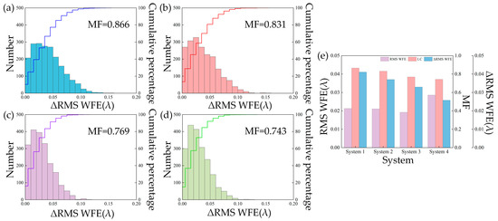
Figure 11.
(a–d) Optical system error sensitivity distribution for “System 1” to “System 4”; (e) MF, RMS WFE and ΔRMS WFE comparison chart for “System 1” to “System 4”.
5. Discussion
5.1. Discussion of the Desensitization Design Method
In recent years, our team has been actively engaged in the investigation of desensitization design methods. We have proposed a series of innovative methods, including the angle-optimized desensitization design method based on optical path difference variation [28], and the local curvature control desensitization design method based on wavefront error variation [30].
This paper provides supplementary analysis on these two desensitization design methods proposed by our team. We developed a mathematical model for a single spherical mirror with the decenter error, as is shown in Figure 1. We proved whether it reduces the sensitivity to tilt errors or decenter errors, which can be achieved by decreasing the incidence angle at the intersection point of the incident ray and the mirror. In the process of gradually expanding the FOV, the working area is enlarged, upgrading the surface type to a freeform surface to increase optimization DOFs is indispensable. Therefore, it is necessary to propose a method to desensitize the freeform optical system. Characterizing the error sensitivity of freeform surfaces involves combining the concept of “micro-elements” used in evaluating freeform surface error sensitivity. Here, the entire freeform mirror is treated as a collection of numerous spheres, and the incidence angle on each sphere is determined by its curvature.
We demonstrate that the incident angle on a spherical mirror can be expressed in terms of curvature, revealing the profound connection between these two desensitization design methods. Thus, an error sensitivity evaluation function, MF, is used for proposing a desensitization design method for freeform optical systems. Compared to some traditional desensitization design methods, this method does not require high demands for the designers, thus, they can modify the evaluation function to be suitable for the optimization process.
5.2. Discussion of the Combined Design Method and Design Results
In this paper, a combined design method for freeform TMA optical systems with a large FOV and low error sensitivity is proposed based on the step-by-step optimization of the FOV and error sensitivity.
The method that we used to obtain a large FOV and low error sensitivity is to expand the FOV and constraint the MF step by step, as shown in Figure 4. By gradually expanding the FOV, the incremental differences between each successive design result are minimal, and it is easier to correct the aberration induced by the expanded FOV. If desensitization is performed after the FOV meets the requirements, it will be difficult to carry out the desensitization design process due to the difference in direction between desensitization and the FOV expansion process. And desensitizing can also gradually narrow the gap between the current structure and the final structure, reducing the complexity of desensitization optimization. Thus, we adopt such a method, and in each round of FOV expansion, error sensitivity is constrained, and an ideal optical system is obtained through surface type upgrading and image quality optimization.
As the FOV expands, according to the aberration theory, the error sensitivity should increase dramatically. As shown in Figure 11, as the MF gradually decreases, the optical system’s error sensitivity also decreases gradually, confirming the correctness of the error sensitivity merit function.
During the design process, we implemented the even aspherical surface on the PM, and applied XY polynomials freeform surface on the TM. The XY polynomial freeform surface on the TM is an effective option for desensitizing off-axis TMA optical systems [3]. Certainly, other types of freeform surfaces can also be used to achieve such designs according to the specific requirements. The sensitivity evaluation function and desensitization design method we proposed are applicable to any smooth and continuous surfaces. And in a further study, the differences in error sensitivity among different types of freeform surfaces will be explored for a more comprehensive and integrated analysis.
6. Conclusions
The freeform TMA optical system with a large FOV and low error sensitivity is robust against misalignments. In this paper, the angle-optimized desensitization design method is extended to reduce decenter error sensitivity. By adopting the concept of “micro-elements”, the error sensitivity merit function for freeform surfaces is constructed. Combined with the FOV expansion process, conducting desensitization in each step of the FOV expansion allows us to gradually approach the ideal goal of error sensitivity and FOV.
A freeform off-axis TMA system with a focal length of 1000 mm, an F-number of 10, and a wide FOV of 20° × 4° was designed using the proposed design method in this paper. The design results demonstrate that the system exhibits high imaging quality, with an RMS WFE of 0.029λ. A series of incremental design results consistently show high image quality and low error sensitivity, confirming the correctness of the evaluation function MF and the effectiveness of the desensitization design method. This design has valuable implications for space optical systems that require high resolution, a large FOV, and low error sensitivity.
Author Contributions
Conceptualization, C.R. and Q.M.; methodology, C.R. and Q.M.; software, C.R.; validation, C.R.; formal analysis, C.R.; investigation, C.R.; resources, Q.M.; data curation, C.R. and Q.M.; writing—original draft preparation, C.R.; writing—review and editing, C.R. and Q.M.; visualization, C.R.; supervision, Q.M.; project administration, Q.M.; funding acquisition, Q.M. All authors have read and agreed to the published version of the manuscript.
Funding
This research was funded by the National Natural Science Foundation of China (62375264, 62235018); the Youth Innovation Promotion Association of the Chinese Academy of Sciences (2019219); the CAS Project for Young Scientists in Basic Research (YSBR-066) and the Civil Aerospace Pre-research Project (D050101).
Data Availability Statement
Data are contained within the article.
Conflicts of Interest
The authors declare no conflicts of interest. The funders had no role in the design of the study; in the collection, analyses, or interpretation of data; in the writing of the manuscript, or in the decision to publish the results.
References
- Liu, X.; Gong, T.; Jin, G.; Zhu, J. Design method for assembly-insensitive freeform reflective optical systems. Opt. Express 2018, 26, 27798–27811. [Google Scholar] [CrossRef]
- Yang, T.; Zhu, J.; Hou, W.; Jin, G. Design method of freeform off-axis reflective imaging systems with a direct construction process. Opt. Express 2014, 22, 9193–9205. [Google Scholar] [CrossRef] [PubMed]
- Qin, Z.; Qi, Y.; Ren, C.; Wang, X.; Meng, Q. Desensitization design method for freeform TMA optical systems based on initial structure screening. Photonics 2022, 9, 544. [Google Scholar] [CrossRef]
- Zhang, B.; Jin, G.; Zhu, J. Towards automatic freeform optics design: Coarse and fine search of the three-mirror solution space. Light Sci. Appl. 2021, 10, 65. [Google Scholar] [CrossRef] [PubMed]
- Lampton, M.L.; Sholl, M.J.; Levi, M.E. Off-axis telescopes for dark energy investigations. Proc. SPIE 2010, 7731, 442–452. [Google Scholar]
- Figoski, J.W. Alignment and test results of the QuickBird telescope using the Ball Optical System Test Facility. In Advanced Telescope Design, Fabrication, and Control. Proc. SPIE 1999, 3785, 99–108. [Google Scholar]
- Hariharan, V.K.; Sundaram, N.S.; Dayashankara, K.S.; Lakshminarayana, V.; Shrivastava, A.K.; Damodaran, A.; Gupta, L.N.; Ganeshan, P.P.; Velayudhan, M.; Rao, B.V.; et al. Assembly, integration and testing of Cartosat-1. In Proceedings of the 2006 9th International Conference on Electromagnetic Interference and Compatibility, Bangalore, India, 23–24 February 2006; IEEE: Piscataway, NJ, USA, 2006; pp. 60–66. [Google Scholar]
- Meng, Q.; Wang, D.; Wang, X.; Li, W.; Yang, X.; Yan, D.; Li, Y.; Cao, Z.; Ji, Q.; Sun, T.; et al. High resolution imaging camera (HiRIC) on China’s first Mars exploration Tianwen-1 mission. Space Sci. Rev. 2021, 217, 42. [Google Scholar] [CrossRef]
- Thompson, K.P.; Rolland, J.P. Freeform Optical Surfaces: A Revolution in Imaging Optical Design. Opt. Photonis News 2012, 23, 30–35. [Google Scholar] [CrossRef]
- Wei, S.; Li, Y.; Ma, D. Sculpting optical fields into caustic patterns based on freeform optics. Optica 2023, 10, 1688–1699. [Google Scholar] [CrossRef]
- Wei, S.; Zhu, Z.; Ma, D. Efficient and compact freeform optics design for customized LED lighting. Opt. Laser Technol. 2023, 167, 109775. [Google Scholar] [CrossRef]
- Zhong, Y.; Gross, H.; Broemel, A.; Kirschstein, S.; Petruck, P.; Tuennermann, A. Investigation of TMA systems with different freeform surfaces. Proc. SPIE 2015, 9626, 229–238. [Google Scholar]
- Zhang, X.; Zhang, J.; Shi, G.; Wu, Y.; Wang, L.; Zeng, F.; Qu, H.; Zhang, J.; Wu, H.; Zhu, Y.; et al. Optical design of off-axis astronomical space telescope based on freeform surfaces. Proc. SPIE 2014, 9293, 198–205. [Google Scholar]
- Reimers, J.; Bauer, A.; Thompson, K.P.; Rolland, J.P. Freeform spectrometer enabling increased compactness. Light Sci. Appl. 2017, 6, e17026. [Google Scholar] [CrossRef]
- Yang, T.; Zhu, J.; Jin, G. Design of free-form imaging systems with linear field-of-view using a construction and iteration process. Opt. Express 2014, 22, 3362–3374. [Google Scholar] [CrossRef]
- Tang, R.; Zhang, B.; Jin, G.; Zhu, J. Multiple surface expansion method for design of freeform imaging systems. Opt. Express 2018, 26, 2983–2994. [Google Scholar] [CrossRef]
- Hou, W.; Zhu, J.; Yang, T.; Jin, G. Construction method through forward and reverse ray tracing for a design of ultra-wide linear field-of-view off-axis freeform imaging systems. J. Opt. 2015, 17, 055603. [Google Scholar] [CrossRef]
- Meng, Q.; Wang, H.; Liang, W.; Yan, Z.; Wang, B. Design of off-axis three-mirror systems with ultrawide field of view based on an expansion process of surface freeform and field of view. Appl. Opt. 2019, 58, 609–615. [Google Scholar] [CrossRef]
- Gu, Z.; Wang, Y.; Yan, C. Optical system optimization method for as-built performance based on nodal aberration theory. Opt. Express 2020, 28, 7928–7942. [Google Scholar] [CrossRef] [PubMed]
- Kuper, T. A new look at global optimization for optical design. Photonics Spectra 1992, 1, 151–160. [Google Scholar]
- Kuper, T. Global optimization finds alternative lens designs. Laser Focus World 1992, 5, 193–195. [Google Scholar]
- Forbes, G.; Jones, A. Global Optimization in Lens Design. Opt. Photonics News 1992, 3, 23–29. [Google Scholar] [CrossRef]
- Sturlesi, D.; O’Shea, D.C. Global view of optical design space. Opt. Eng. 1991, 30, 207–218. [Google Scholar] [CrossRef]
- Fuse, K. Method for Designing a Refractive or Reflective Optical System and Method for Designing a Diffraction Optical Element. US Patent No 6567226 20 May 2003. [Google Scholar]
- Rogers, J.R. Using global synthesis to find tolerance-insensitive design forms. Proc. SPIE 2006, 6342, 63420M. [Google Scholar]
- Isshiki, M.; Gardner, L.; Gregory, G.G. Automated control of manufacturing sensitivity during optimization. Proc. SPIE 2004, 5249, 343–352. [Google Scholar]
- Jeffs, M. Reduced manufacturing sensitivity in multi-element lens systems. Proc. SPIE 2002, 4832, IMC4. [Google Scholar]
- Qin, Z.; Wang, X.; Ren, C.; Qi, Y.; Meng, Q. Design method for a reflective optical system with low tilt error sensitivity. Opt. Express 2021, 29, 43464–43479. [Google Scholar] [CrossRef]
- Meng, Q.; Wang, H.; Wang, W.; Yan, Z. Desensitization design method of unobscured three-mirror anastigmatic optical systems with an adjustment-optimization-evaluation process. Appl. Opt. 2018, 57, 1472–1481. [Google Scholar] [CrossRef]
- Qin, Z.; Meng, Q.; Wang, X. Desensitization design method of a freeform optical system based on local curve control. Opt. Lett. 2023, 48, 179–182. [Google Scholar] [CrossRef]
- Deng, Y.; Jin, G.; Zhu, J. Design method for freeform reflective-imaging systems with low surface-figure-error sensitivity. Chin. Opt. Lett. 2019, 17, 092201. [Google Scholar] [CrossRef]
- Sasian, J.; Descour, M. Power distribution and symmetry in lens systems. Opt. Eng. 1998, 37, 1001–1005. [Google Scholar] [CrossRef]
- Deng, Y.; Tan, Y.; Wu, X.; Zhu, J. Local tolerance and quality evaluation for optical surfaces. Optica 2022, 9, 1039–1049. [Google Scholar] [CrossRef]
Disclaimer/Publisher’s Note: The statements, opinions and data contained in all publications are solely those of the individual author(s) and contributor(s) and not of MDPI and/or the editor(s). MDPI and/or the editor(s) disclaim responsibility for any injury to people or property resulting from any ideas, methods, instructions or products referred to in the content. |
© 2024 by the authors. Licensee MDPI, Basel, Switzerland. This article is an open access article distributed under the terms and conditions of the Creative Commons Attribution (CC BY) license (https://creativecommons.org/licenses/by/4.0/).